
International Journal of Scientific & Engineering Research, Volume 5, Issue 3, March-2014 954
ISSN 2229-5518
Indraprassad.G.T, Sakthivel.E, Ramesh.J, Janarthanan.R, Bagyalakshmi.R, Kamesh.G
ABSTRACT
Health monitoring of induction motor have been a challengIng task for the engineers and mainly in industries. There are many health monitoring methods including vibration monitoring, thermal monitoring, chemical monitoring but these monitoring methods require expensive sensors (or) specialized tools whereas current monitoring out of all does not require additional sensors. Current monitoring is non-intrusive and may even be implemented in the motor control center remotely from the motors being monitored. Motor Current Signature Analysis(MCSA) uses the current spectrum of the machine for locating characteristic fault frequencies. W hen fault is present, the frequency spectrum of the line current becomes different from healthy motor. These proposed methods recognize the fault signatures produced in induction motor and estimate the severity of the faults under different load conditions.
Key words: Condition monitoring, induction motor, Lab view, fuzzy logic.
—————————— ——————————
The three phase Induction motors due to their simple construction, high reliability and low cost, have dominated in the field of electromechanical energy conversion by having more than 75% of motors in use. Though the probability of breakdowns of Induction motors is very low, the fault diagnosis has become almost indispensable. Particularly when they are working in sophisticated automated production lines. To decrease the machine down time and improve stability on line diagnostic features are to be necessarily incorporated with the drives. In modern industry lots of machines depend on mutual operation, and the cost of unexpected breakdowns is very high. Thus condition monitoring techniques comprising of fault diagnosis and prognosis are of great concern in industry and are gaining increasing attention. A three-phase Induction motors may experience several types of fault conditions which include Over load, Ground fault, Line to Line fault, Unbalanced supply voltage, Over voltage, Under voltage, Single phasing, Turn to Turn fault. When one of the three-phase to the motor is open, single phasing situation occurs. This result increased
Positive and negative sequence currents and hence excessive heating. Unbalance supply voltage results in negative sequence voltage. It leads to increase in positive
and negative sequence current components. Ground and
line faults are prevalent in motors than other power system devices. These faults are detected by observing the zero sequence current. Similarly Turn to Turn short and coil open faults can cause current unbalance. From the foregoing analysis it is clear that the appearance of various faults is simply determined by the stator current values. In general stator currents and voltages are preferred because the sensors required are usually present in the drive considered. The conventional monitoring systems have a number of limitations such as inflexible, high cost, hardware limitations which are heavily dependent upon specialized instruments. In recent years the monitoring and fault detection of electrical machines have moved from traditional techniques to Artificial intelligence and virtual instrumentation techniques. But the Virtual instrumentation approach helps us to get rid of the above said drawbacks. In addition to this, additional scientific visualizations and advanced analysis can also be added in the form of virtual instruments with minimal cost. Because of its overall versatility as an engineering tool, the software package Lab View is chosen in most of the engineering problems. In this paper Condition monitoring system for Induction motor has been developed in both simulation models (Mat lab/Simulink) as well as in real time (Lab View). For the past fifteen years there has been a substantial amount of research into the creation of new Condition Monitoring techniques for Induction Motor drives. New
IJSER © 2014 http://www.ijser.org
International Journal of Scientific & Engineering Research, Volume 5, Issue 3, March-2014 955
ISSN 2229-5518
methods have been developed which are now being used in industries and research is continuing with the development of new and alternative on-line diagnostic techniques. However it is still the end users who have to make the selection of most appropriate and effective monitoring system to suit their particular Induction Motor drive systems.
The possible detection methods to identify the motor faults are listed as follows.
1. Vibration Monitoring.
2. Motor Current Signature Analysis (MCSA).
3. Electromagnetic field monitoring using search coils.
4. Chemical analysis (Lubricating oil debris, cooling gas).
5. Temperature measurement.
6. Infrared measurement.
7. Acoustic noise measurement.
8. Radio frequency emission monitoring.
9. Partial Discharge measurement.
The monitoring and fault detection of electrical machines are moved from traditional techniques to artificial intelligence and virtual instrumentation techniques. In order to achieve low cost on line monitoring, the diagnosis algorithm will be simple enough to be executed using industrial microprocessor in real time.
Many engineers and researchers have focused on incipient fault detection and preventive maintenance, which aim at preventing motor faults from happening. Usually, devices such as fuses, overload relays, and circuit breakers protect induction motors. Research has focused on different motor failure mechanisms, causes of stator and rotor failures, analyses of these failures, methodologies to determine whether a motor is suitable for extended service, test methods, the test equipment needed, application and limitations of these test procedures, data gathering, specific benefits, and costs. In addition to developing motor protection schemes in reaction to faults due to misoperation, disturbances, sudden failure, etc., motor incipient fault detection problems have also been attracting significant attention and interest. On- line monitoring of induction machines in critical applications has been increasingly necessary to improve their reliability and to minimize catastrophic failures. Microprocessor-based monitoring systems are of particular interest because they can be used for regular analysis of machine variables and to predict possible fault conditions, so that preventive
maintenance can be organized in a cost-effective manner. Different researchers have addressed the importance and economic benefits of on- line motor monitoring and fault detection approaches. General methods of cost–benefit analysis have been applied to investigate the financial viability of such systems. Methods for the evaluation of the improvement of machine reliability by monitoring of systems have also been discussed. Different invasive and noninvasive approaches for motor incipient fault detection/diagnosis have been reported. Many of the motor incipient fault detection/diagnosis schemes can be applied noninvasively on-line without the need of expensive monitoring equipment by using a microprocessor. With proper monitoring and fault detection/diagnosis schemes, the incipient faults can be detected in their early stages; thus, maintenance and downtime expenses can be reduced, and reliability can be improved. System identification and parameter estimation have previously been proposed for fault detection/diagnosis in motors. As opposed to conventional techniques, where expensive equipment or accurate mathematical models are required, fuzzy logic and neural network (NN) technologies can be used to provide inexpensive but effective fault detection mechanism alternatives.
In a three-phase induction motor framework, stator currents and rotor angular velocity are measured under different motor friction and load torque The magnitude of motor friction and load torque affect motor operations, which, in turn, affect speed and current measurements. However, the magnitude of the motor friction cannot be measured directly. Furthermore, the effects of incipient motor friction faults are highly coupled with effects of load torque. The aim of this paper is to estimate motor friction based on appropriate measurements. A three-phase induction motor simulation program, Motor SIM, is used to provide the experimental data for the motor under different operating conditions to evaluate NN/FZ motor fault detector. Nonlinear effects, such as temperature and saturation, were also incorporated into the simulation model. The specifications of this motor are given in. The data consist of three-phase stator currents and rotor angular velocity acquired under variable motor friction and load torque values.
IJSER © 2014 http://www.ijser.org
International Journal of Scientific & Engineering Research, Volume 5, Issue 3, March-2014 956
ISSN 2229-5518
An open-loop volts/Hertz control is assumed for the drive. Only two current sensors are used and a mechanical one is not considered. The goal is not the study of the drive performances, so a closed loop is not assumed. In this paper, the standard stationary reference frame is used to evaluate the stator current pattern evolution when abnormal conditions occur in the inverter. In a three-phase inverter, the short circuit of a switching device is not studied because the protection system (e.g., input fuses, circuit breaker) designed conservatively stops the whole system immediately more effi- ciently than any other technique. In healthy and ideal conditions, the stator current pattern in the Concordia reference frame is a circle with a constant radius in steady-state. The synchronous rotating frame (Park components) is not considered, as it requires the calculation or the estimation of the frame angle. When a fault occurs in the electronic circuit of a switching device leading to a misfiring, the stator current pattern is biased in such a direction that allows the fault diagnosis. The asymmetry in the output voltage creates a dc component which introduces in the sinusoidal current, a dc component whose sign indicates the bias direction. Due to the pulse width modulation (PWM), the locus is obviously not a circle. The other patterns in case of misfiring are easily obtained by rotating the previous pattern of 120 degree.
Analog Stator
Current
DAQ Signal
Conditioner
Analog to
Digital
Converter
Signal
Processing
Fault Detection
Expert
System

IJSER © 2014 http://www.ijser.org
International Journal of Scientific & Engineering Research, Volume 5, Issue 3, March-2014 957
ISSN 2229-5518
Condition monitoring of the induction motor is a process of continuous evaluation of the health of the motor throughout its serviceable life. Condition monitoring and protection are obviously closely related functions. Condition monitoring should be designed so as to preempt faults that can occur in the induction motor. It can be extended to provide primary protection, but its real function must always be to attempt and to recognize the development of faults at an early stage. Such advanced warning is desirable since it allows maintenance person greater freedom to schedule outages in the most convenient manners. By condition monitoring we can reduce unexpected failures and downtime, increase the time for standards maintenance, and reduce maintenance and operational cost.
Fuzzy Logic has emerged as a profitable tool for the controlling of subway systems and complex industrial processes, as well as for household and entertainment electronics, diagnosis systems and other expert systems. Fuzzy logic is basically a multivalued logic that allows intermediate values to be defined between conventional evaluations like yes/no, true/false, etc. Notions like rather warm or pretty cold can be formulated mathematically and processed by computers. In this way an attempt is made to apply a more human-like way of thinking in the programming of computers. Fuzzy controllers are the most important application of fuzzy theory. They work rather different than conventional controllers; expert knowledge is used instead of differential equations to describe a system.
Fuzzy rules and membership functions are constructed by observing the data set. For the measurements related to the stator currents, more insight into the data are needed, so membership functions will be generated for Negative Medium(NM), Negative Small(NS), Zero(Z), Positive Small(PS), Positive Medium(PM). For the measurement related to the stator condition, it is only necessary to know if the motor condition is good or damaged or Seriously Damaged. The stator related faults that have been investigated in this study are
1. Turn-to Turn short,
2. Break in stator winding
3. Unbalance in input Voltage
4. Open phase
The steps in building Condition Monitoring system are:
1. Determine the fuzzy control input. The current is the input to the fuzzy controller.
2. Determine the fuzzy control output. The output is the condition of the motor.
3. Choose the word descriptions for the status of input and output.
Output Status Word Descriptions:
1. Good
2. Damaged
3. Seriously Damaged.
The next step is to determine the degree of membership for
both input and output variables. This can be done by knowledge base only.
The development of computer technologies, transducer technologies, and signal processing techniques together with artificial-intelligence (AI) techniques has made it possible to implement Condition Monitoring (CM) more efficiently on any electrical equipment. It is expected to make CM systems more reliable, more intelligent and cheaper, so that they can be widely employed even in small scale industries.
CM is a technique served for Condition-Based Monitoring (CBM). Earlier to this time-based maintenance had been the mainly used maintenance strategy for a long time.
Time-based maintenance, to examine and repair the machines offline either according to a time schedule or running hours, may prevent many failures. However, it may also cause many unnecessary shutdowns and
IJSER © 2014 http://www.ijser.org
International Journal of Scientific & Engineering Research, Volume 5, Issue 3, March-2014 958
ISSN 2229-5518
unexpected accident will still occur in the intervals. Manpower and time and money were wasted because the activity of maintenance with little information of the current condition of the machines. But the CBM will let operators know more about the state of machines and indicate clearly when and what maintenance is needed.
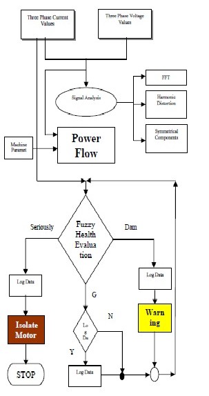
Here the input quantities are the three phase input voltage and the three phase stator current signals. A fuzzy logic
controller has been designed to evaluate the state of the motor based on the stator current magnitude. Based on the output of the fuzzy controller protective actions are carried out.
The total Instrumentation system incorporates
1. Data Acquisition.
2. Signal Processing
3. Fuzzy Control
In the motor fault diagnosis process, time domain current signals are captured from sensors. The diagnostic expert then uses both time domain and frequency domain signals to study the motor condition and determines what faults are present. However, experienced engineers are often required to interpret measurement data that are frequently inconclusive. A fuzzy logic approach may help to diagnose induction motor faults. Fuzzy logic is reminiscent of human thinking process and natural language enabling decisions to be made based on vague information. Fuzzy logic is shown in figure 11. it allows items to be described as having a certain membership degree in a set. While conducting fault diagnosis, there are several situations in which an object is not obviously "Good" or "Damaged", but may fall into some interior range. According to the fact that induction motor condition interpretation is a fuzzy concept. Here the motor condition is described using linguistic variables. Fuzzy subsets and the corresponding membership functions describe stator current amplitudes. This linguistic input can be expressed directly by a fuzzy system. The internal structure of fuzzy controller is shown in figure 12. The stator current signal contains potential fault information.
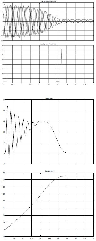
Fig. 15. Three phase Stator currents and Percentage Health of Induction motor (Normal Operation)
Fig. 16 Developed Torque and Speed of Induction motor
IJSER © 2014 http://www.ijser.org
International Journal of Scientific & Engineering Research, Volume 5, Issue 3, March-2014 959
ISSN 2229-5518
Fuzzy systems rely on a set of rules. These rules, allow the input to be fuzzy, i.e. like the natural way that
Ia = { μia (Iaj) Σ Ia }
Ib = { μib (Ibj) Σ Ib } Ic = { μic (Icj) Σ Ic }
CM = { μcm (cmj) Σ CM }
Where Iaj , Ibj , Icj and cmj are elements of the discrete
universe of discourse Ia, Ib, Ic and CM .the optimized rule
base has been developed so as to cover all the healthy and the faulty conditions of the motor.
Fig. 11. Complete structure of Fuzzy Controller
Fig. 12. Internal structure of Fuzzy Controller
In this case the stator current Ia, Ib, and Ic are considered
input variables to the fuzzy system. The stator condition, CM is chosen as output variable. All the system inputs and outputs are defined using fuzzy set theory. The input variables are interpreted as linguistic variables, with Negative Medium(NM), Negative Small(NS), Zero(Z), Positive Small(PS), Positive Medium(PM). Similarly the output variable stator condition (CM) is interpreted as linguistic variables, with Good, Damaged, and Seriously Damaged. Fuzzy rules and membership functions are constructed by observing the data set. There are 31 if-then rules used and the membership function for input and ouput variables.
A Lab View based measurement and health evaluation system has been developed and implemented. This application allows fast failure state estimation. The more detailed investigation to point out the difficult conditions of the machine under different stator fault conditions of induction motor can be performed. This is a highly versatile technology for condition monitoring and fault analysis of motors. It solves the shutdown Problems and ensures safe working environment in continuous process Industry.
• Fault Detection and Diagnosis in an Induction Machine
Drive: A Pattern Recognition Approach Based on Concordia Stator Mean Current Vector.Demba Diallo, Member,IEEE, Mohamed El Hachemi Benbouzid, Senior Member, IEEE, Denis Hamad, and Xavier Pierre.
• A Survey of Methods for Detection of Stator-Related Faults in Induction Machines. Rangarajan M. Tallam, Member, IEEE, Sang Bin Lee, Member, IEEE, Greg C. Stone, Fellow, IEEE, Gerald B. Kliman, Life Fellow, IEEE, Jiyoon Yoo, Thomas G. Habetler, Fellow, IEEE, and Ronald G. Harley, Fellow, IEEE
• Fault Detection in Induction Machines Using Power Spectral Density in Wavelet Decomposition. Jordi Cusidó, Student Member, IEEE, Luis Romeral, Member, IEEE, Juan A. Ortega, Member, IEEE, Javier A. Rosero, and Antonio García Espinosa, Member, IEEE
• High Frequency Resolution Techniques for Rotor Fault
Detection of Induction Machines. Alberto Bellini, Member,
IEEE, Amine Yazidi, Associate Member, IEEE, Fiorenzo Filippetti, Member, IEEE, Claudio Rossi, Member, IEEE, and Gérard-André Capolino, Fellow, IEEE.

G.T.INDRAPRASSAD is pursuing eighth semester, Bachelor of Engineering in the discipline of Electrical and Electronics Engineering at Knowledge Institute of Technology, Salem, affiliated under Anna University, Chennai, India. He is presented number of papers in
symposium and presented 2 papers in International Conference and 1 National Conference and participated in many workshops conducted by the reputed institutions and company. He has participated in many of the robotics events conducted my IIT- Bombay and went till the final round and also doing minor research in Condition monitoring of Induction Motor.
E.SAKTHIVEL is pursuing eighth semester, Bachelor of Engineering in the discipline of Electrical and Electronics Engineering at Knowledge Institute Of Technology, Salem, affiliated under Anna University, Chennai, India. He is presented
number of papers in symposium and presented 2 papers in
International Conference and 1 National Conference. . He is doing minor research in Condition monitoring of Induction Motor.
IJSER © 2014 http://www.ijser.org
International Journal of Scientific & Engineering Research, Volume 5, Issue 3, March-2014 960
ISSN 2229-5518

R.JANARTHANAN is pursuing eighth semester, Bachelor of Engineering in the discipline of Electrical and Electronics Engineering at Knowledge Institute Of Technology, Salem, affiliated under Anna University, Chennai, India. He is
presented number of papers in symposium and presented 2 papers in International Conference and 1 National Conference. . He is doing minor research in Condition monitoring of Induction Motor.
J.RAMESH is pursuing eighth semester, Bachelor of Engineering in the discipline of Electrical and Electronics Engineering at Knowledge Institute of Technology, Salem, affiliated under Anna University,
Chennai, India. He is presented number of papers in
symposium and presented 2 papers in International
Conference and 1 National Conference. . He is doing minor research in Condition monitoring of Induction Motor.
R.BAGYALAKSHMI is currently working as an Associate Professor in the Department of Electrical and Electronics Engineering at Knowledge Institute of Technology, Salem. She received his UG degree in the discipline of Electrical and
Electronics Engineering from Government College of Technology under Anna University and got PG degree in Power Electronics and Drives discipline from Vinayaga Mission Kirupananda Variyar Engineering College, Salem. She has the industrial experience of 12years and teaching experience of 5.5years. Currently pursuing Ph.D. in Anna University, Chennai. She has published papers in International level Journals and presented papers in National and International level conferences. She has guided number of project for students. She has organized about 5 guest lectures in various fields. Her research interests lie in the field of Power Electronics, Neural
Network and Electrical Machines.
G.KAMESH is currently working as a Lab Technician of 3.8years experience in Department of Electrical and Electronics Engineering at Knowledge Institute Of Technology, Salem and
also he is pursuing his part time BE degree in Vinayaga
Mission Kirupananda Variyar Engineering College. He has presented many National and International Conferences in VIT and many other colleges. His research interest lies in Embedded System & VLSI Design
IJSER © 2014 http://www.ijser.org