International Journal of Scientific & Engineering Research, Volume 5, Issue 7, July-2014 37
ISSN 2229-5518
Free Space Optical Communication: The Main
Challenges and Its Possible Solution
S. Babani1 , Y. S. Abdulmalik2 , A. Abdul’aziz2, A. Z. Loko2, M. M. Gajibo2
1Department of Electrical Engineering / HAFEDPOLY P.M.B 5004, Kazaure, Jigawa State Nigeria
2Universiti Teknologi Malaysia, 81310 Skudai, Johor Malaysia
sbabani2000@gmail.com
Abstract— Free Space Optics (FSO) is a promising solution for very high data rate point-to- point communication. Recently, it has received significant attention as a possible alternative to overcome the bottleneck connectivity problem and as a supplement to more conventional RF/microwave links. FSO communications has become attractive for a number of reasons including unlicensed spectrum and a narrow beam width. Moreover, FSO becomes the best solution to solve the problems occurred in conventional wireless system by using optical fiber because it uses laser light to transmit data between two points. The FSO uses beam of light to provide optical connection that can send and receive video, voice, and data information. In this paper Free Space Optical communication concept will be introduced. In addition, the performance of FSO communication link will analysis and illustrates its main challenges and it possible solutions.
Index Terms— Atmospheric Turbulence, Buffering, Fso, Fso link performance, Retransmission.
—————————— ——————————
1 INTRODUCTION
HE free-space optical communication (FSO) is an optical communication technology that uses light propagating in free space to transmit data for telecommunications or
computer networking. "Free space" means air, outer space, vacuum, or something similar. This contrasts with using solids such as optical fiber cable or an optical transmission line. The technology is useful where the physical connections are im- practical due to high costs or other considerations [2]. FSO system is cost-effective and an attractive solution for high- speed communication systems and provides very large band- width where a data rate of 100 Gbit/s can be achieved over a distance of 1-4 km. Furthermore, propagating laser radiation over the atmosphere termed FSO communications is attractive for a number of reasons including unlicensed spectrum and a narrow beam width [9]. In the Free Space Optical communica- tion, the technology is fundamentally based on transmitting optical signal into the free space and the air or vacuum space acts as the medium for signal transmission., It offers data rates comparable to optical fiber communications but at a fraction of its deployment cost. Furthermore, it’s extremely narrow laser beam width offers spatial multiplexing and multiple links capabilities in a given location [1]. Conventional wired and radio frequency (RF) wireless communications suffers “last-mile” data transmission, where local area network (LAN) based FSO system has the potential to solve the “last-mile” problem for the foreseeable future as a bandwidth in excess of
2THz. Besides high data transfer rate, a direct line-of-sight FSO link offer numerous advantages compared to the conven- tional systems [3].Moreover, FSO link consumes relatively low power and also provide greater security to the data as the data carrying light rays are confined to very narrow area as the light beam is of small diameter. The FSO signals are also less sensitive to the electromagnetic interferences [9]. FSO system is like optical system, the main components of the transmitter
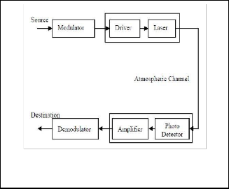
and receiver are modulator, optical source, optical detector and a demodulator. Basic block diagram of a Free Space Opti- cal system is given in the Fig.
Fig. 1. Basic block diagram of the FSO system [9]
The modulation and the demodulation both are done in the electrical domain and commonly used modulation techniques used are Pulse Position Modulation (PPM) and On-Off Keying (OOK). Apart from these modulation techniques, the research is going on to implement other modulation techniques along with some coding techniques to get the optimum performance of the system. Free-space point-to-point optical links can be implemented using infrared laser light, although low-data- rate communication over short distances is possible using LEDs. Infrared Data Association technology is a very simple form of free-space optical communications [6]. The various
IJSER © 2014 http://www.ijser.org
International Journal of Scientific & Engineering Research, Volume 5, Issue 7, July-2014 38
ISSN 2229-5518
issues related to the free space optical system are- atmospheric turbulence, scintillation, fog, smoke, building sway etc. These are the parameters which affect the performance of the system. In this paper, FSO concept and its link performance are mainly discussed. Atmospheric turbulence is described using the gamma–gamma probability distribution. Lastly, several of FSO impairments are declared.
2 FREE SPACE OPTICAL LINK PERFORMANCE
The performance of an FSO link is primarily dependent upon the climatology and the physical characteristics of its installa- tion location. The transmitted optical beam traversing the at- mosphere can be absorbed, scattered or displaced depending on the atmospheric condition, thus setting the fundamental limits of FSO systems. In general, weather and installation characteristics that impair or reduce visibility also affect FSO link performance. A typical FSO system is capable of operating at a range of two to three times that of the naked eye in any particular environmental condition [5]. The overall system performance of a link is quantified using a link margin de- rived from the link equation. This equation is analogous to the link equation for any radio frequency (RF) communication link. Starting with the transmit power the designer identifies all link degradations and gains to determine the received sig- nal level. The received signal level is then compared with the sensitivity of the receiver, thus giving the link margin [10]
2.1 Channel With out Atmosperic Disturbance
In the basic free-space channel the optical field generated at the transmitter propagates only with an associated beam spreading loss. In this system the performance can be deter- mined directly from the power flow. The signal power re- ceived PR [W] depends on the transmit power PT [W], transmit antenna gain GT receives antenna gain GT the range loss Gr, and system-dependent losses Asystem link:  (1) Assuming a Gaussian beam under filling the transmit aper- ture, the transmit antenna gain GT is :
 (2) Where Q [rad] is the full-angle e^(-2) divergence of the trans- mit beam. The range loss GR depends on the link propaga- tion distance L and is given by:
 (3) Further, the receive antenna gain, with telescope aperture
diameter (antenna size) D, is given by:
 (4) The Asystem link reflects all the other system-dependent
losses. It includes losses due to link misalignment, telescope
losses, losses due to splitting out light for tracking systems,
etc. Because of the absence of atmospheric effects the link
margin Mlink in dB is given by [10]:

(5)
Where: received power PR [dBm] must be given on a loga- rithmic scale. Sr [dBm] is the required power at the receiver to achieve an expected communication performance, also called receiversensitivity.
2.2 Atmospheric Effects
It is well known that clouds, rain, snow, fog, haze, pollu- tion are atmospheric factors that affect our viewing of distant objects. These same factors also affect the transmission of a laser beam through the atmosphere.As transmission through clouds or heavy fog or haze is normally not possible, because the attenuation exceeds several tens of dB/km. The signal un- der clear-sky weather conditions is attenuated because of ex- tinction caused by air molecules and aerosols. The transmit- tance T of laser radiation that has propagated over a distance L is described by the Beer’s law [10]:  (6)
(6)
The positive extinction coefficient (αs *λ) describes the ex- tinction level of the medium. Atmospheric trace gases lead to strong and broad absorption bands, each consisting of a multi- tude of fine absorption lines. Based on the spectral distribution of these bands, the so called atmospheric optical transmission windows with low signal losses of the propagating beam can be calculated by evaluating thousands of absorption lines in the spectral range from 0.3 μm to14 μms [10]. In addition to absorption, scattering has also to be taken into account. This can be described by the Rayleigh scattering coefficient. Gener- ally, scattering effects decrease monotonically with wave- length and altitude. Even in optical windows some extinction must be considered, e.g. due to Rayleigh scattering. A rough estimate for the clear-sky extinction is based on the meteoro- logical parameter visibility V.
3 ATMOSPHERIC TURBALANCE
Laser radiation experiences amplitude and phase fluctuations due to atmospheric turbulence when it propagates through the vacuum. This effect is the consequence of random varia- tions in the atmospheric index of refraction due to correspond- ing changes in atmospheric temperature. According to [7], the induced thermal gradients may be viewed as close-packed spherical regions or eddies having statistically varying diame- ters and indexes of refraction. Atmospheric turbulence is well studied in the literature and various models exist to describe it. The most used model is apparently the log normal turbu- lence. This model has gained considerable attention in the lit- erature because it is mathematically convenient and tractable, but the model is only valid in single scattering event character- izing weak turbulence. When multiple scatterings are experi- enced especially in longer link ranges, the incident wave be- comes increasingly incoherent and log normal model becomes invalid [7].
3.1 Gamma-gamma modeling
The gamma-gamma model of turbulence is based upon such modulation process which assumes that the small scale and large scale effects are responsible for the changes occur- ring in the path of radiated light signal travelling through tur- bulent atmosphere. This channel model also considers a region between transmitter and receiver which is known as Fresnel zone. The Fresnel zone is an elliptical area between transmitter
IJSER © 2014 http://www.ijser.org
International Journal of Scientific & Engineering Research, Volume 5, Issue 7, July-2014 39
ISSN 2229-5518
and receiver around the line-of-sight path between them. The
Fresnel zone helps in carrying the strongest signal to the re- ceiver. The eddies cells, which are smaller than the Fresnel zone result in small signal effect, i.e. scattering and the eddied cells larger than the Fresnel zone result in a large scale effect known as refraction [5].
The gamma-gamma turbulence model proposed by An- drews et al is based on the modulation process where the fluc- tuation of light radiation traversing the turbulent atmosphere is assumed to consist of small scale and large scale effects. The eddies cells, which are smaller than the Fresnel zone or the coherence radius result in small signal effect, i.e. scattering and the eddied cells larger than the Fresnel zone result in a large scale effect known as refraction [5]. The small scale ed- dies are assumed to be modulated by the large scale eddies. Consequently, the received radiance is defined as the product of two statistically independent random processes Ix and I y .  (7)
(7)
Ix and Iy arise from the large scale and small scale turbulent eddies respectively. The gamma-gamma model for the proba- bility density function (pdf) of receiving irradiance fluctuation which is based on the assumption that both the large and small scale effects are governed by the gamma distribution is therefore given by [6].
Based on the atmosphere turbulence model adopted here and assuming strong turbulence, we can obtain the approxi- mate analytic expression for the covariance of the log- amplitude fluctuation of plane and spherical waves which is also known as Rytov variance, given by [8]:  (8)
(8)
3.2 Free Space Optical Impairments
Fso suffers many factors that degrade the performance of the system like rain, scintillation, fog, smoke, building sway etc. The research is going on to make the FSO system more efficient and accurate.
3.2.1 Rain and Snow attenuation
The rain and the snow are one of the factors that restrain the line-of-sight link between the transmitter and the receiver. The snow is divided into two types-wet snow and dry snow. The amount of attenuation due to wet snow is higher than the attenuation occurring due to dry snow [3]. The dry snow ef- fects on the low snow rate, whereas wet snow effects at high snow rate. The amount of attenuation decreases as the visibil- ity increases during the snowfall.
3.2.2 Scintillation
Atmospheric scintillation can be defined as the changing of light intensities in time and space at the plane of a receiver that is detected a signal from a transmitter located at a dis- tance. The received signal at the detector fluctuates as a result of the thermally induced changes in the index of refraction of the air along the transmit path. These index changes cause the atmosphere to act like a series of small lenses that deflect por- tions of the light beam in and out of the transmit path. The time scale of these fluctuations is on the time scale of these fluctuations are the order of milliseconds, approximately equal to the time that it takes a volume of air the size of the beam to move across the path, and therefore is related to the wind speed [3].
3.2.3 Alignment
One of the key challenges with FSO systems is maintain- ing transceiver alignment. FSO transceivers transmit highly directional and narrow beams of light that must impinge upon the receive aperture of the transceiver at the opposite end of the link. A typical FSO transceiver transmits one or more beams of light, each of which is 5–8 cm in diameter at the transmitter and typically spreads to roughly 1–5 m in diameter at a range of 1 km. Adding to the challenge is the fact that FSO receivers have a limited FOV, which can be thought of as the receiver ’s “cone of acceptance” and is similar to the cone of light projected by the transmitter. For a FSO link to function, it is very important that both the transmitted beam of light and the receive FOV cone encompass the transceiver at the oppo- site end of the link [3].
3.2.4 Free Space Path Loss
Free-space path loss (FSPL) is the loss in signal strength that would occur in a line-of-sight path through free space (usually air), with no obstacles nearby to cause reflection or diffraction. It does not include factors such as the gain of the antennas used at the transmitter and receiver, nor any loss associated with hardware imperfections [3]. The equation for free space path loss (FSPL) and the effect of link length are given below:
 (9)
(9)
4 THE MAIN POSSIBLE SOLUTION
In fact, all modalities of free space optical communication can offer solutions to the last mile problem, affording flexible and rapid connectivity. However, radio frequencies carry heavy tariffs and licensing fees. We have outlined the primary chal- lenges limiting the extensive implementation of FSO and in the next subsections we present some alternative solutions to these. However, on a macro level, a link is either operational or not depending on whether or not the signal-to-noise ratio (SNR) is too low. If the link operation is inadequate, there may be alternative ways to transmit the data by circumventing the failed link. Such approaches can he generalized as solutions at the net-work layer, However optical wireless networks have features that demand special consideration. A few solution is below for a broad review of optical network technology and solution the reader is referred to [12]
4.1 Buffering
When atmospheric transmission is low and the signal is severely attenuated (e.g., due to fog), there is likely to be con- siderable error in detection. In these cases it may be wise simply to store the data and transmit it later when the envi- ronmental obstruction has passed. This tactic is familiar with all networking environments, but the vast data rates of optical communication systems would result in huge volumes of storage for even brief outages. Therefore, a part-optical part- electronic buffer would probably be needed to cope with the amount of data to be stored [13]. If the link capacity is re- duced, but not inoperative, it is possible to suspend low- priority transmissions while selectively continuing with high- priority data. For instance, email transmissions could be buff-
IJSER © 2014 http://www.ijser.org
International Journal of Scientific & Engineering Research, Volume 5, Issue 7, July-2014 40
ISSN 2229-5518
ered even for several hours in severe weather conditions. Precedence could then be given to real-time voice data or transmissions attributed the high quality of service (QoS).
4.2 Retransmission
Another alternative solution at the networking level is to retransmit the data. This may be performed when the recep- tion has been found to be faulty or is anticipated to be defec- tive. Retransmission can be particularly helpful when there is strong turbulence in the atmosphere, since repeated transmis- sions may increase the probability of correct detection. In the presence of severe building sway, retransmission is likely to succeed since the building is effectively entering and exiting the transmission path, and the accumulation of signals can be sufficient for successful communication.
4.3 Rerouting Transit Paths
Networking between nodes can alleviate communication problems by enabling alternative routes from sender to recipi- ent when the direct connection is disabled. Clearly, only local malfunctions of a link can be combated, and then only on the assumption that sufficient other participant links are operative to close the loop between transceivers. The availability of in- dividual links can he validated continuously using sophisti- cated protocols to optimize efficiency. The best route can he selected, while taking into account other traffic demands. Re- routing requires point-to-multipoint transceivers, with either dedicated transmitters for each link or pointing mechanisms. A high level of redundancy and short link ranges increase the networks rerouting capabilities.
5 CONCLUTION
Now that FSO communication is a reality, creative solutions are sought to combat the main problems encountered. In this paper we have reviewed some of the prominent ideas pub- lished in the professional literature, the Free Space Optics Sys- tem (FSO) is becoming the solution for conventional wireless system which face problems of last-mile service providing. In this paper the combined fundamental of FSO, link perfor- mance, impact of atmospheric turbulence, path loss factor and free space optical communication system is presented. The basic characteristics of a laser beam provide the following ad- vantages of FSO links:
A narrow beam guarantees high spatial selectivity so there is no interference with other links, the high available bit rate allows them to be applied in all types of networks, the optical band lies outside the area of telecommunication regulation; therefore no license is needed for operation, the small size and small weight of optical terminals enables links to be easily integrated into mobile systems.
REFERENCES
[1] D. Killinger, “Free space optics for laser communication through the air,” Optical. Photon. News, vol. 13, no. 3, pp. 36–42, Oct. 2002.
[2] Sridhara K, “ Free space optical communication,” International Journal of
Latest Research in Science and Technology, Vol. 1, Issue 3, pp. 202-205. Oct.
2012.
[3] Bloom, S., Korevaar, E., Schuster, J. and Willebrand, H. 2003. “Understanding the performance of free-space optics”, Journal of Optical Networking, Optical
Society of America, Vol. 2, Issue 6, pp.178-200.
[4] J. Li, J. Q. Liu, and D. P. Taylor, “Optical communication using sub- carrier PSK intensity modulation through atmospheric turbulence channels,” IEEE Transaction in Communication., vol. 55, no. 8, pp.
1598–1606, Aug. 2007.
[5] Wang, Z., Zhong, W. D., Fu S. and Lin, C. 2009. “Performance Com- parison of Different Modulation Formats Over Free-Space Optical (FSO) Turbulence Links with Space Diversity Reception Technique”, IEEE Photonics Journal, 2009 Vol.1, No.6. pp. 277-285.
[6] Barua, B. 2011. “Comparison the Performance of Free-Space Optical Communication with OOK and BPSK Modulation under Atmospher- ic Turbulence”, International Journal of Engineering Science and Technology (IJEST), Vol. 3, No. 5,pp 4391-4399.
[7] W. O. Popoola and Z. Ghassemlooy, “BPSK Subcarrier Intensity Modulated Free-Space Optical Communications in Atmospheric Turbulence,” Journal Of Lightwave Technology, Vol. 27, No. 8,pp
967-973, April 15, 2009.
[8] X. Zhu and J. M. Kahn, "Free-space optical communication through atmospheric turbulence channels," IEEE Transactions on Communi- cations, vol. 50, pp. 1293-1300, August 2002.
[9] Teejbir and S. Gurpartap, “Improvement in performance of free space optical communication,” International Journal of Applied In- formation Systems (IJAIS), Vol. 2, No. 4, pp. 2249-0868, May 2012.
[10] H. Henniger, and O. Wilfert, “An Introduction to free space optical communication”. RADIOENGINEERING, VOL. 19, NO. 2, JUNE
2010.
[11] M. Bass, "Atmospheric optics," in Handbook of Optics ,Third Edition ed., vol. 5, M. Bass, Ed. McGraw-Hill, 2010, pp. 3.3.
[12] H.E. Nistazakis1 T.A. Tsiftsis2 G.S. Tombras1 “Performance analysis of free-space optical communication systems over atmospheric tur- bulence channels” ; Published in IET Communications Received on
18th April 2008 ,Revised on 18th November 2008
[13] S. Mohammad Navidpour, Member, IEEE, Murat Uysal, Member, IEEE, and Mohsen Kavehrad, Fellow, IEEE ‘BER Performance of Free-Space Optical Transmission with Spatial Diversity”, IEEE TRANSACTIONS ON WIRELESS COMMUNICATIONS, VOL. 6, NO. 8, AUGUST 2007
[14] Md. Tawabur Rahman, Shahid Iqbal, Md. Monjurul Islam,: Modeling and Performance Analysis of Free Space Optical Communication System”, [EEE/OSA/[APR International Conference on [infonnatics, Electronics & Vision
IJSER © 2014 http://www.ijser.org