1
International Journal of Scientific & Engineering Research Volume 4, Issue 1, January-2013
ISSN 2229-5518
Flat Plate Heat Exchanger Design for MTR Reactor Upgrading
Adel Alyan Fahmy
Atomic Energy Authority, Reactors Department, 13759 Cairo, Egypt
adelalyan@yahoo.com
Abstract: The purpose of the present study is to investigate the performance of plate heat exchanger used in a research reactor for updating it and raise its power to 10 (MW).The objective also to extend the present knowledge of the thermo-hydraulic performance of PHE with consideration of channel geometries (Chevron angles). In this study the surface area density, the total number of corrugated plates and the pressure drop will be study at different Chevron angles, also the corrugation pitch. The effect of variation of Chevron angle on the heat transfer coefficient will be study. The Chevron angle will vary from (30º to
60º).This study aims to obtain an applicable model which is able to design flat plate heat exchanger for many applications.
Index Terms— Compact heat exchanger, corrugated plates, friction factor, forced convection.
—————————— • ——————————
1. INTRODUCTION
Compact heat exchanger consists of plates instead of tubes to separate the hot and cold fluids. Because each of the plate has very large surface area, the plates provide
each of the fluids with an extremely large heat transfer area.
Due to the high heat transfer efficiency of the plates, plate type
heat exchanger is very compact when compared to a shell and
tube heat exchanger with the same heat transfer capacity. In the 1930's PHEs were introduced to meet the hygienic demands of the diary industry. Today the PHE is universally used in many fields; heating and ventilating, breweries, dairy, food processing, pharmaceuticals and fine chemicals, petroleum and chemical industries, power generation, offshore oil and gas production, onboard ships, pulp and paper production etc. plate heat exchanger also find application in water closed circuit cooling water systems using potentially corrosive primary cooling water drawn from sea, river, lake, or cooling tower to cool non-corrosive secondary liquid flowing in a closed circuit.
2- Chevron Corrugations
Geometrical features of the chevron type of corrugation are in Figure.4. A single plate comprises four corner ports and the corrugation area. The corrugation pattern has a chevron angle �, evaluated as the angle between the corrugation troughs to the vertical axis. In a PHE unit plates are installed with the apex of the chevron pointing in opposite directions. The chevron design brings four main effects, it
1. Increases flow turbulence level,
2. Increases the effective heat transfer area (typically
by a factor of 1.1 – 1.25),
3. Increases the stiffness of the plate pack,
4. Increases turbulence and high wall shear force
which reduces fouling.
efficient [2].The surface enlargement factor ,<I, is another
important parameter, which is defined as the ratio of actual heat transfer area to the projected area. Most commercial plates have enlargement factors usually in a relatively small range of 1.1 – 1.25 [3]. <I can be calculated approximately, for a sinusoidal corrugation profile, from a three-point integration formula [4].
3- Flow Arrangements
The flow arrangement in a PHE can be very flexible. There are basically four types of configuration that be used, as will be shown below in Figure1., which are related to flow distributed inside or between channels
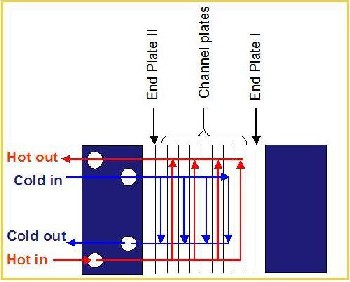
The chevron angle of commercially available plates varies between the extremes of a about 25 to 65º, and is perhaps the most important geometrical parameter of PHE's relating to thermal and hydraulic performance[1]. Conventional plates have approximately sinusoidal profiles. Corrugations that are asymmetrical in profile are not common and found to be less
IJSER © 2013 http://www.ijser.org
Figure.1. Flow distribution inside channels
2
International Journal of Scientific & Engineering Research Volume 4, Issue 1, January-2013
ISSN 2229-5518
3.1. Inside Single Channel
� � 1 (1+
1+ X


2 + 4 1+ X 1
(1)
In a single channel, the flow of one fluid can be either
diagonal or parallel, depending on the sealing arrangement on
the ports. A diagonal arrangement refers to the flow that

6 \ 2 )
Where:
enters and leaves the channel at diagonally opposite ports, whereas in the parallel (or vertical, same-side) arrangement

X = 2.7t .a
(2)
the flow enters and leaves on the same side.
3.2. Pass
The hydraulic diameter of the plate heat exchanger is obtained as follows:
4.Ac .L p
=4.Ac .L p
4 (2.aW p .N c ).L p
(3)
Pass refers to a group of channels in which the flow is in the same direction. The two streams in a PHE unit can have different pass arrangements, single or multiple, which the latter consisting of passes connected in series.

D h = P .L = A
wet p t
4.Friction factor

=
2.L .N .N p .N c
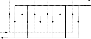
3.3. U and Z Type Arrangement in Single-pass Flows
One of the correlations for the friction of a plate heat exchanger with Chevron pattern is provided by Martin [7]. The fanning friction factor is:

-2
r l
f =

cos � +
1- cos �

1
( f 1 2

0.045.tan � + 0.09.sin � + o
(3.8).f 1
L \
cos � ) J
(4)
Figure.2. U arrangement of Plates
Where:
16

f o =
e
f o = (1.56.Ln (R e ) - 3.0)

f = 149.25 + 0.9625
For Re < 2000 (5)
For Re>2000 (6) For Re <2000 (7)
1
e
Figure.3. Z arrangement of Plates
The so-called U and Z type arrangements are found in single- pass flows. For any one fluid stream if the inlet and outlet
9.75

1 0.289 e
5. Nusselt Number
For Re>2000 (8)
ports are on the same side of the exchanger unit, it is called a
U type arrangement; otherwise it is a Z type, as shown in
Figures 2 and 3.
The surface enlargement factor can be calculated approximately for sinusoidal corrugation by:
Martin[1] also provided the Nusselt number correlation for a plate heat exchanger with Chevron pattern as:

Nu = h.Dh
K f
(9)
IJSER © 2013 http://www.ijser.org
3
International Journal of Scientific & Engineering Research Volume 4, Issue 1, January-2013
ISSN 2229-5518
1
N u = 0.205.P 3 (f .R 2 .sin 2.� )
1
0.374 ( 16

(10)
The hot and cold water properties at the average fluid temperatures are obtained as follows:
\ s )

(T T hot -water =
_ hot _1) + (T
2
_ hot _ 2 )
(15)
(T _ cold _ 1) + (T
_ cold _ 2 )
Where º10 < � < º 80 and Kf is the thermal conductivity of the
fluid and ps is the dynamic viscosity at the wall
temperature,(p / ps)=1 may be used with the assumption the
p changes moderately with temperature.
6. Pressure drop
The total pressure drop in a plate heat exchanger is composed of the friction pressure drop of the channels (�Pf) and the port pressure drop (�Pp). We assumed that the pressure drop due to the elevation (gravity)change is negligible. The frictional pressure drop is calculated using the following equation:
2.f .L G 2

T cold -water = 2 (16)
Table.1 The hot and cold water properties:
( )
�Pp =


.
Dh p
.N p
(11)
The mass velocity for each fluid at the port of the plate heat 1
exchanger is defined by:
•

G = 4.m
7t .D 2
(12)
Where : Dp is the port diameter. The port pressure drop for each fluid is then calculated by:
�P =

1.5.N 2
(13)
p 2.p
The total pressure drop is the sum of equation (11) and (13).
The thermal conductivity of the plate (Stainless steel AISI 304)
�Pt = �Pf
+ �Pp
(14)
(kw) 14.9 (W/m.K).
The port diameter is designed such that the port pressure drop is usually less than 10 percent of the total pressure drop, but it may be as high as 25 to 30 percent in some designs.
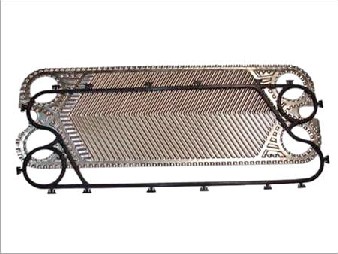
Figure.4. Plates with chevron-type corrugation pattern for a plate heat exchanger.
Table.2. Geometric Parameters:
IJSER © 2013 http://www.ijser.org
4
International Journal of Scientific & Engineering Research Volume 4, Issue 1, January-2013
ISSN 2229-5518
The projected area for the plate is calculated by:
Ap1 = 2W.
So,
A p1 = A p 2
p .Lp .N 01
(25)
(26)

<!= L X .N X
W p
Where is the enlargement factor.
(27)
4.a
h <!
(28)
Where, Dh is the hydraulic diameter.
The flow area Ac for each fluid is obtained using the following equation:
A =2.aW.
p .N c1
(29)
Figure.5. Flat Plate Heat Exchanger Channels.
C 1 C 2
(30)
The number of wave length per single a plate is obtained by dividing the PHE width (Wp) by the corrugation pitch (X).
The mass velocity, velocity and Reynolds number are defined using the general definition as:

N = w p
X X
(17)
•
G1 = m1
Ac1
(31)
The number of channels for each fluid is calculated by
dividing the total number of channel (NTOT +1) by two and
V =G
1
the number of passes Np as shown in the following equation: p1
(32)
N 01

= N T OT +1
2.N p
(18)
Re1 =
G 1.Dh
(33)
The number of channels per one fluid is the same as for the other fluids.
1
After updating the final sizing, the velocity may be checked against the reasonable values.
N 01 = N 02
(19)
The corrugation amplitude is given by the following equation, the amplitude is expressed as a function of the PHE height,(Hp).
Martin's [7] developed with the Darcy friction factor is
modified with the fanning friction factor as follows:
a = ( 1 1 .( Hp - 8 1
(20)
F =1.56.(LN )(R
- 3.0)-2
(34)


\ 2 ) \ N T OT + 1 )
01 e1
Otherwise,
The corrugation ratio (y) is defined as:

y = 4. a
(21)
16
01
e1
- -2
(35)
(36)
X
The plate (PHE) design is commonly limited to (y<1). The
F02 =1.56.(LN )(Re2
Otherwise,
16
3.0)
corrugation length is given using the following equation:
F02 = (37)
R e2
X ( 2.7t .a 1
( 2.7t 12
F = 9.75
for Re1 ;; 2000 (38)

LX = J 1+ X

.cos - X
X
.dX
(22)
m1 (R )0.289
0 \ ) \ )
e1
Otherwise,
The heat transfer area for each fluid is calculated considering
= 149.25 + 0.9625
m1 R
(39)
two surfaces per channel as follows:
A = 2.L .N .L .N
(23)
e1
9.75
m 2 (R )0.289
for Re2 ;; 2000 (40)
A = A
(24)
Otherwise,
IJSER © 2013
http://www.ijser.org
5
International Journal of Scientific & Engineering Research Volume 4, Issue 1, January-2013
ISSN 2229-5518
= 149.25 + 0.9625
m 2 R
(41)
U .A = 1
(46)
e2
The fanning friction factor for each fluid is given using the
r( 1 ( 1 l
1 + 8 + 1
following equation:
h .A
L\ 1 1 )
K
\ W )
h .A
2 2 J
r l
( 1

F = cos(� ) + 1- cos(� )
1 0.5 3.8.F
(42)
8.t- NTU Method:
( F 1
0.045.tan(� ) + 0.09.sin.(� ) + 01
cos(� )
m1 )
The heat capacity for both fluids is defined, and then the
L \ ) J
-2
minimum and maximum heat capacities are obtained.
r l
(43)
•
C1 = m1. 1
(47)
Cp
( 1
cos(� ) 1- cos(� )
(48)
F 2 = +
C 2 = m 2 .Cp2

( F 0.5 3.8.F 2
0.045.tan(� ) + 0.09.sin.(� ) + 02 \ m )
cos(� )
L \ ) J
C min
= min . C .C
1 2
(49)
7. Overall thermal-hydraulic performance
C max = max .(C .C )
The heat capacity ratio Cr is defined as:
C

Cr = min
C max
(50)
(51)
PHE'S are usually much more thermally efficient their
So, the NTU can be calculated from the following equation:
shell- tube counterparts, particularly for liquid/liquid duties. Film coefficients can be two to four times those for tubular units of the same duty, at the same or even lower pressure drops [4].At normal working ranges the overall heat transfer coefficient U can be expected to be 2300 – 5800 (W/m2.K), depending on plate corrugation and flow conditions [5]. The
highest U value that could be achieved by a PHE was reported

NTU = U .A C min
The effectiveness of the PHE for counter flow is obtained using the following equation:
[-N T U .(1-Cr 1]

s = 1 -e \ )
[-NT U .(1-Cr 1 ]
1-C .
(52)
(53)
up to 8500 (W/m2.K), making it capable of working with film
re \ )
coefficient three to five times high than tubular or spiral-plate design [6]. The augmented heat transfer performance of a PHE is due to several enhancement mechanisms, which directly result from the complex plate surface characteristics. These surface effects include disruption and reattachment of boundary layers, swirling motion of the fluids, continuous change in flow directions and velocity, combining to promote early transition to turbulence and produce exceptionally high film coefficients of heat transfer.
The heat transfer coefficient of the hot fluid is given by:
The heat transfer rate for the PHE is obtained as:
q = s.C .(T i -T i 1
min \ hot cold )
9.Pressure drop:
9.1Pressure Drop Components
Pressure drop in a PHE consists of three contributions:
1. frictional pressure drop within the plate passages
2. pressure drop due to elevation change
3. Pressure drop in inlet and outlet manifolds (port).
(54)
( k 1 r

1= 1 . 0.205. Pr
1 1 2 l
3.(1) 3.F . Re .sin(2.� )0.374
(44)
The frictional channel pressure drops for both fluids are obtained using the following equations:
( 1 ( 1
h D \ 1)
1 \ 1)
\ h ) L J
The heat transfer coefficient of the hot fluid is given by:
2.f .L
2
(G 1
( 1 r
k
1 1 2 l
P 1 = 1 P . \ 1 ) .N p
(55)
h = 2
. 0.205.(Pr 2 )3.(1) 3.F .(Re 2 )
.sin(2.� )0.374
(45)
�
f D p
1
2 D 2
\ h ) L
J
�P =
=2.f 2.LP .
(G )2
.N p
(56)
The overall heat transfer coefficient is obtained by using the
following equation:
f 2 Dh p2
The connection and port pressure drops are obtained using the following equations:
•
m
G P1 =
IJSER © 2013 http://www.ijser.org

4. 1
7t .D p 2
(57)
6
International Journal of Scientific & Engineering Research Volume 4, Issue 1, January-2013
ISSN 2229-5518
•
G P 2
4.m

= 2
7t .D p 2
GP 2
(58)
(59)

�Pp =1.5.Np.
1
1
2.p1
�Pp
2
G P 2

=1.5.Np. 2
p2
98
94
(60)
90
86
B= 30 deg B= 40 deg B= 50 deg
B= 60 deg
10.Results: 82
78
1200
1100
1000
900
800
B= 30 deg
B= 40 deg
B= 50 deg
B= 60 deg
74
70
66
62
6 7 8 9 10 11 12
X (mm)
700
600
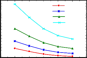
Figure.8. Effect of Chevron angle on the hot fluid pressure drop.

220
500
400
6 7 8 9 10 11 12
X (mm)
Figure.6. Surface area density and corrugation pitch.
210
200
190
180
170
B= 30 deg B= 40 deg B= 50 deg B= 60 deg

1.600x10⁷
1.500x10⁷
B=30 de g.
160
150
1.400x10⁷
1.300x10⁷
140
6 7 8 9 10 11 12
X (mm)
1.200x10⁷
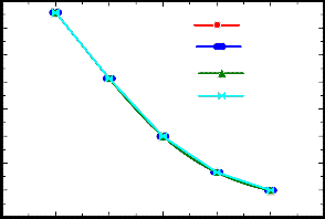
Figure.9. Effect of Chevron angle on the cold fluid pressure drop.
1.100x10⁷
40 60 80 100 120 140 160 180
NTOT
Figure.7. Effect of total number of plates on the compact heat exchanger heat transfer.
IJSER © 2013 http://www.ijser.org
7
International Journal of Scientific & Engineering Research Volume 4, Issue 1, January-2013
ISSN 2229-5518
1 .440x108
1 .260x108
1 .080x108
9 .000x107
7 .200x107
5 .400x107
3 .600x107
1 .800x107
B= 30 deg
B= 40 deg B= 50 deg B= 60 deg
6 7 8 9 10 11 12
X (mm)
Fig.(8,9) illustrate the relation between the pressure drop and corrugation pitch at different chevron angle .with decreasing the corrugation pitch the pressure drop increases due to increasing of fluid velocity between the corrugations. At constant corrugation pitch, the pressure drop increases with increasing of the Chevron angle due to increasing of fluid turbulence also the passage become more tortuous and offers greater hydrodynamic resistance.
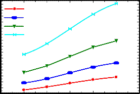
Figure.10. Effect of Chevron angle on the hot fluid heat transfer coefficient.
2.880x10⁸
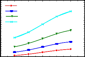
Fig.(10,11) shows the relation between the heat transfer coefficient and the corrugation pitch at different Chevron angle .The corrugated pattern on the thermal plate induced a highly turbulent fluid flow. The high turbulent in the plat heat exchanger leads to an enhanced heat transfer.
2.520x10⁸
2.160x10⁸
1.800x10⁸
1.440x10⁸
1.080x10⁸
7.200x10⁷
3.600x10⁷
B= 30 deg
B= 40 deg B= 50 deg B= 60 deg
6 7 8 9 10 11 12
X (mm)
4-CONCLUSION
Theoretical model have been introduced to investigate heat transfer characteristic of a commercial corrugated plate heat exchanger with different Chevron angles and corrugation pitch. The effect of Chevron angles variation on the heat transfer coefficient is simulated. It found that, as the corrugation angle is reduced from (90º), the flow passage become more tortuous and offers greater hydrodynamic resistance. The heat transfer carried by the fluid in a corrugated plate heat exchanger increased by increasing the total number of the corrugated plates due to the increase of the effective heat transfer area. With increasing the Chevron
Figure.11. Effect of Chevron angle on the cold fluid heat transfer
coefficient.
angle the friction factor increase, hence increasing the pressure
drop.
Fig.(6) shows the relation between the surface area density
NOMENCLATURE:
�
Chevron angle.
deg.
and the corrugation pitch. The surface area increases with
decreasing the corrugation pitch. The chevron angle has no
<I
PHE
Surface enlargement
factor.
Plate heat exchanger.
effect on the surface area density X
a
Fig.(7) depicts the effect of the total number of plates on the Dh
compact heat exchanger heat transfer. The heat transfer of the Ac
Lp compact heat exchanger increases with increasing the number
Corrugation pitch. mm Corrugation mm amplitude.
Hydraulic diameter. mm
Free flow area. m2
Heat exchanger m
length.
of heat exchanger plates due to increasing of the effective heat
transfer area.
Pwet At Wp
Perimeter length. mm
Heat exchanger m
IJSER © 2013 http://www.ijser.org
8
International Journal of Scientific & Engineering Research Volume 4, Issue 1, January-2013
ISSN 2229-5518
width.
Nc Number of cold
channel.
f Fanning friction
factor.
Re Reynolds number.
Nu Nusselt number.
Subscripts:
t total.
f channel.
h
p
�Pp
�Pt
�Pf
G
N p
T hot -water
Tcold -water
Heat transfer coefficient. dynamic viscosity. Port frictional pressure drop.
Total pressure drop.
Frictional pressure drop of the channels. Mass velocity.
Number of passes.
The average of hot water temperature. The average of cold water temperature.
W/m^2.K
N.s/m^2 kPa
kPa kPa
Kg/m^2.s

ºC
ºC
P passes.
1 hot water.
2 cold water.
01 hot channels.
02 cold channels.
REFERENCE
[1] Kakac S. and Liu H., 2002, Heat Exchangers: Selection, Rating, and Thermal
Design, 2nd ed., CRC Press.
[2] Focke W.W., 1985, Asymmetrically corrugated plate heat exchanger plates,
International Communications in Heat and Mass Transfer,
T _ hot _1
T _ hot _2
T _ cold _1
T _ cold _2
The temperature of hot water inlet
The temperature of
hot water outlet.
The temperature of cold water inlet
The temperature of cold water outlet.
ºC vol.12, no.1, pp.67-
77.
ºC
[3] Kumar H., 1984, The plate heat exchanger: construction
ºC and design, IChemE
Symposium Series, no.86, pp.1275-1288.
ºC
[4] Bond M.P., 1981, Plate heat exchangers for effective heat
N Number of wave
X length.
N Number of channels.
y Corrugation ratio
X length.
transfer, The ChemicalEngineer, no.367, pp.162-167.
[5] Raju K.S. and Chand J., 1980, Consider the plate heat exchanger, Chemical
Engineering, vol.87, no.16, pp.133-144.
A
Ap1
The corrugation
The heat transfer area
Plate projected area.
M
m^2 m^2
[6] Carlson J.A., 1992, Understand the capabilities of plate-
and-frame heat
exchangers, Chemical Engineering Progress, vol.88, no.7, 26-
31.
m1
NTU
Cr
Modified fanning
friction factor.
Number of Transfer
UNIT
Heat capacity ratio
[7] Martin H., 1996, A theoretical approach to predict the performance of chevron type plate heat exchangers, Chemical Engineering and Processing, vol.35, no.4,pp.301-310.
C Heat capacity
m^2.kg/K.S^3
£ The effectiveness of
the PHE.
q The heat transfer rate for the PHE.
p The density
Cp The specific heat. k Thermal
conductivity.
• The mass flow rate.
m
Pr Prantle number
W
Kg/m^3
J/kg.K W/m.K
Kg/s
[
IJSER © 2013

http://www.ijser.org