International Journal of Scientific & Engineering Research, Volume 5, Issue 4, April-2014 1135
ISSN 2229-5518
Finite Element Analysis of Disc Brake for
Aluminium Alloys
Abhishek Kumar Tiwari, Akhilesh Kumar Tiwari, Pramod Yadav, Harigovind Singh Yadav, Shyam Bihari Lal
—————————— ——————————
1 INTRODUCTION
Brake is device by means of which artificial frictional resistance is applied to moving machine member in or- der to stop the motion of a machine.
In the process of performing this function the brakes ab sorb either kinetice energy of the moving member or the po tentioal energy given up by energy absorbed by brakes is dis- sipated in the form of heat. This heat is dissipated in to the surrounding atmosphere.
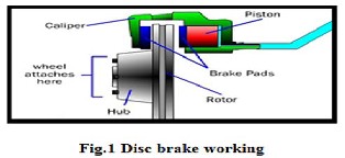
A disc brake comprises of a cast iron disc bolted to the wheel hub and a stationary housing called caliper. The caliper connected to some stationary part of the vehicle like the axle casing or the stub axke and is cast in two parts each part com- prising a piston. In between each piston and the disc there is afriction pad carried in position by retaining pins spring plates etc. Passages are drilled in the caliper for the fluid to enter or leave each housing. These passages are also associated to an- other one for bleeding. Each cylinder holds rubber sealing ring between the cylinder and piston.
The principal used is the applied the applied force (pres-
sure) plays on the brake pads which comes into contact
with the moving disc. At this point time due to friction the
relative motion is constrained.
• Author name- Abhishek Kumar Tiwari, Akhilesh Kumar Tiwari, Pramod Yadav ,Harigovind Singh Yadav Student of Mechanical engi- neering at B.I.T. Gorakhpur
• Co-Author name- Shyam Bihari Lal, Asst. Prof. Department of mechanical engineering, B.I.T. Gorakhpur,
E-mail: shymefme@gmail.com
When the brakes are employed hydraulically actuated piston act the friction pads in to contact with the disc applying equal and opposite forces on the later. On freeing the brakes the rub- ber sealing ring acts returm spring and draws back the piston and the friction pads away from the disc.
The main parts of the disc brake are:
1: The brake pads.
2: The caliper which contains the piston.
3: The rotor which is mounted to the hub.
The finite element method is a mightily tool to find the numer- ical solution of wide range of engineering trouble. The method is general enough to deal any complex shape or geometry for any material under different boundry and loading circum- stances. The generally of the finite element method fits the analysis requirement of todays complex engineering systems and design where closed from solution of govering equilibri- um equation are usually not usable. In addition it is an efficient design tool by which designers can execute parametrice design studies by considering various design cases, (different shapes, materials, loads etc.)
The method origined in the aerospace industry as a tool to study sress in a complex airframe structres. It grows out of what was called the matrix analysis method used in aircraft design. The method has gained increased popularity among both or structure may be separated in to small elements of fi- nite dimensios called finite elements the original body or the structure is then viewed as an assemblage of these elements.
IJSER © 2014 http://www.ijser.org
International Journal of Scientific & Engineering Research, Volume 5, Issue 4, April-2014 1136
ISSN 2229-5518
matrices) and load vectors.
Element type soliod10 node quadratic tetrahedral is shown in fig.2.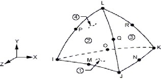
187)
Pro/e and ansys workbench software are used for the FE analysis. The crankshaft kis modeled in 3D using pro/e software. IGES file is generated and the imported in ANSYS workbench software. The 10 node tetragonal elements (SOLID 187) were used as shown in figure finite element mesh was generated using tetragonal ele- ment with element lenth of .5 mm (2262 elements). The reason for Choosing thids element was to make the geometrical parts of a complicated mechanical compoment so enable us to gain more authentice results based on the high technique of fatigue life cacu- lation.
SOLID187 element is a higher order 3-D 10-node element. SOLID187 has a quadrice displacement behavior and is well suit- ed to modeling irregular meshes (such as those produced from various CAD/ACM system) .the element is defined by 10 node having three degrees of freedom at each node. Translation in the nodal x,y, and z direction . The element has plasticity large deflec- tion and large strain capabilities for simulating deformation of nerly incompressible elastoplastice materials and fully incom- pressible hyperlastice materials.
search for the optimum own solution.
A product development cycle typically admits the following steps.
• Build your model in the pro-Engineer system.
• Prototype the design.
• Test the prototype in the field.
• Valuate the results of the field’s tests.
• Modify the design based on the field test results.
Structural analysis is the most usual application of the finite ele- ment method .The term structural (or structural ) involves civil engineering .
Structures such as bridges and buildings bust also naval aeronau- tical and mechanical structures such as ship hulls aircraft bodies and machines housings as well as mechanical parts such as pis- tons machine parts and tool.
There are seven types of structural analysis usable in ANSYS. One can do the following type of structural analyses.
1. Static analysis.
2. Modal analysis.
3. Harmonice analysis.
4. Transient dynamice analysis.
5. Spectrum analysis.
6. Buckling analysis.![]()
7. Explict dynamice analysis.
Name | Aluminum Alloy |
Model type | Linear Elastic Isotropic |
Default Failure Criterion | Max von Misses Stress |
Yield Strength | 1.65e+0.008 N/m2 |
Tensile Strength | 3.0e+0.008 N/m2 |
Elastic Modulus | 7e+011 N/m2 |
Poisson’s Ratio | 0.33 |
Mass Density | 2600 kg/m3 |
Shear Modulus | 3.189e+010 N/m2 |
First of all we have prepared assembly in pro/ E for crankshaft and save as this part as IGES for Exporting in to ANSHYS workbench environvement import IGES mode in ANSYS workbench simulation module.
IJSER © 2014 http://www.ijser.org
International Journal of Scientific & Engineering Research, Volume 5, Issue 4, April-2014 1137
ISSN 2229-5518

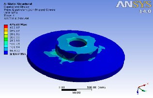
Fig.3 Equivalent stress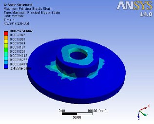
Fig.4 Maximum principal elastic strain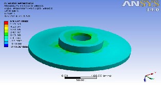
Fig.5 Maximum principal stress
Fig.6 Middle principal elastic strain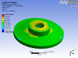
Fig. 7 Middle principal stress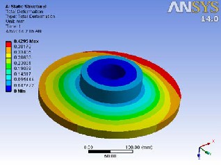
Fig. 8 Total deformation
IJSER © 2014 http://www.ijser.org
International Journal of Scientific & Engineering Research, Volume 5, Issue 4, April-2014 1138
ISSN 2229-5518 
Fig.12 Maximum principal elastic strain
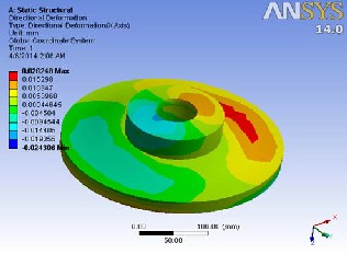
Fig. 9 Directional deformation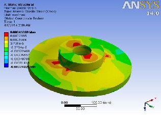
Fig. 10 Normal elastic strain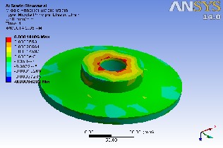
Fig. 11 Middle principal elastic strain
8. CONCLUSION
By noticing the Structural analysis results using Aluminum alloy stress assesses are within the permissible stress value. So using Aluminum Alloy is good for Disc Brake. By observing the fre- quency analysis, the vibrations are less for Aluminum Alloy than other materials since its natural frequency is less. And also weight of the Aluminum alloy reduces almost 3 times when compared with Alloy Steel and Cast Iron since its density is very minus. Thereby mechanical efficiency will be raised. By observing analy- sis results, Aluminum alloys are suitable material for Disc Brake.
[1] Finite Element Method, J.N.Reddy.
[2] Maitra, G.M, 2004, Hand Book of Gear Design, Ta- taMcGrawHill, New Delhi.
[3] Liles, G. D. 1989. Analysis of disc brake squeals using finite element methods. SAE paper 891150, pp. 1138–1146.
[4] S.Mahalingam, R.E.D Bishop, 1974, “Dynamic loading of Gear tooth”, Journal of sound and vibration, 36(2), pp179189 9. S.H.Choi,J.Glienicke, D.C.Han, K.Urlichs, April 1999, “Dynamic Gear Loads due to coupled lateral, Torsional and Axial Vibrations in a helicalGeared System” , Journal of vibration and acoustics, Vol 121.
[5] Zeping Wei., 2004”Stresses and Deformations in Involute spur gears by Finite Element method,” M.S, Thesis, College of Gradu- ate Studies and research, University of Saskatchewan.
[6] Mugeo Dong, Sok Won Kim, Nam-Ku, “Thermo physical Properties of Automotive Brake Disk Materials”, Department of Physics, University of Ulsan pp-680 – 749.
[7] Guangqian g Wu, Lin He, Xianjie Meng, (2009), “Numerical Study on the Vibration Characteristics of Automobile Brake Disk and Pad”, IEEE transactions, pp-1798-1802.
IJSER © 2014 http://www.ijser.org