International Journal of Scientific & Engineering Research, Volume 6, Issue 2, February-2015 107
ISSN 2229-5518
Failure Modes and Effects Analysis of Magneto- Rheological Brake
Bhau K. Kumbhar, Pranit M. Patil, Satyajit R. Patil, Suresh M. Sawant
Abstract— In this work, an effort has been made to study the reliability analysis of the system using the Failure Modes and Effects Analysis (FMEA) technique. FMEA is a development tool used to identify failures and effects on system, products or services. In addition to identifying failure modes and failure mode effects, FMEA provides for quantification and categorisation of failure information in order to allocate and prioritize the risk. The greatest impact of FMEA is in pre-production phases of new product or system development in order to provide failure free systems and products during implementation. FMEA is a versatile tool that has many expressions and that can be integrated with the statistical and software tools to provide for a comprehensive view of risk. Thus, the various possible causes of failure and their effects of a magneto-rheological (MR) brake along with the ways of prevention are discussed in this work.
Index Terms— MR Brake, FMEA, Probability, Risk Priority Number (RPN), Recommendations.
.
—————————— ——————————
Magneto rheological (MR) brake is type of brake, which works on the principle of properties of MR fluid. A magneto- rheological fluid is smart fluid which changes its phase from liquid to the solid on the application of lagnetic field and vice versa only within few mili seconds [1].
In the case of all fluids the variation of viscosity with tem- perature is reversible but this does not allow the viscosity to be controlled easily. In the case of MR the fluid viscosity becomes intelligently controllable using the magnetic field. This change of viscosity up to the solid condition is reversible and is the basic feature of MRF technology [2], [3].
MR brake actuates in following manner; when magnetic field is applied, viscosity of fluid suddenly increases due to a chain like structures. This chain-like structure restricts the mo- tion of the fluid and therefore changes the rheological behavior of the fluid. The MR-effect is produced because of this re- sistance to flow caused by the chain-like structure. Since there is no mechanical linkage in this brake so the stopping distance
& stopping time to stop the vehicle is less [4].
Reliability is the probability of a device performing its pur-
pose adequately for the period intended under the given oper-
ating conditions [5], [6].
Reliability is carried out by two ways [7], (a) Qualitative Analysis:
1. Failure mode effective analysis (FMEA)
2. Fault tree Analysis (FTA)
(b) Quantitative Analysis:
1. Probabilistic Risk Assessment (PRA)
2. Statistical Process Control (SPC)
————————————————
• Bhau K. Kumbhar is currently persuing masters degree program in Auto- mobile Engineering from RIT, Islampur, Shivaji Universit, India, Email: bkumbhar2050@gmail.com
• Pranit M. Patil is currently working as an assistant professor with Gharda
Institute of Technology, Khed (MS), India.
• Satyajit R. Patil is currently working as an Assistant Professor with RIT,
Islampur, Shivaji University, India.
Failure mode and effect analysis (FMEA) is primarily a quality planning tool. It is useful in developing features and goals for both products and processes, in identifying critical prod- uct/process factors and designing counter measures to poten- tial problems, in establishing controls to prevent process errors, and in prioritizing process subunits to ensure reliability.
Failure mode and effect analysis is a tool that examines po- tential product or process [8].
The FMEA process is typically utilized in three areas of product realization and use, namely design, manufacturing and ser- vice. A design FMEA examines potential product failures and the effects of these failures to the end user, while a manufactur- ing or process FMEA examines the variables that can affect the quality of a process. The aim of a service FMEA is to prevent the misuse or misrepresentation of the tools and materials used in servicing a product [8].
There is not a single, correct method for conducting an FMEA; however the automotive industry and the U.S. Department of Defense (Mil-Std-1629A) have standardized procedures/ pro- cesses within their respective realms. Companies who have adopted the FMEA process will typically adapt and apply the process to meet their specific needs [8].
The FMEA process supports the design process by
• Objectively evaluating the design through a knowledgea-
ble team,
• Improving the design before the first prototype is built,
• Identifying specific failure modes and their causes,
• Assigning risk-reducing actions that are tracked to clo-
sure.
Successful implementation of FMEA will
• Improve the reliability and quality of product while iden-
tifying safety issues,
• Increase customer satisfaction,
• Reduce product development time,
• Track corrective action documentation,
• Improve product and company competitiveness,
• Improve product image.
IJSER © 2015 http://www.ijser.org
International Journal of Scientific & Engineering Research, Volume 6, Issue 2, February-2015 108
ISSN 2229-5518
Following steps are consider for processing the Failure Mode
Effect Analysis (FMEA) [8].
• Identify all components or systems at given level of the
design hierarchy.
• List the function of each identified component or system.
• Identify failure modes for each component/system. Typi-
cally there will be several ways in which a component can
fail.
• Determine the effect (both locally and globally) on the sys-
tem.
• Classify the failure by its effects on the system operation.
• Determine the failure’s probability of occurrence.
• Identify how the failure mode can be detected (may point
out what needs to be inspected on a regular basis).
• Identify any compensating provisions or design changes to
mitigate the failure effects.
A group of experts goes through the design of a system, con-
siders all possible faults of all involved components and at-
tempts to identify their impact on the fulfillment of the func-
tionality and safety of system. When potential failure modes
are identified, corrective action can be taken to eliminate them
or to continually reduce a potential occurrence. The FMEA also documents the rationale for the chosen manufacturing process. It provides for an organized critical analysis of potential failure
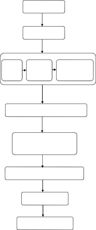
Identify all po- tential items
Define the system to be analyzed
Construct block- diagram
For each item, iden- tify failure modes
Define their effect on the item, on the system, and on the mission
modes and the associated causes for the system being defined. The technique uses occurrence and detection probabilities in conjunction with severity criteria to develop a risk priority number (RPN) for ranking corrective action considerations [9].
Performing the task is costly, because precious expert work- ing hours are spent, and it is error prone, because human anal- ysis tends to be incomplete. It is also repetitive, because, at least in theory, it should be applied after major design modifications. The procedure described in is summarized in Figure 1 [9].
1. Failure -the way in which a design fails to perform as intend-
ed or according to specification.
2. Effect- the customer resulting from the failure mode.
3. Cause -which an element of the design resulted in a failure
Mode.
It is important to note that the relationship between and within
failure modes, effects and causes can be complex. For example,
a single cause may have multiple effects or a combination of
causes could result in a single effect. To add further complexity,
causes can result from other causes, and effects can propagate
other effects [10].
An effective FMEA identifies corrective actions required to prevent failures from reaching the customer; and to assure the highest possible yield, quality, and reliability Designers often focus on the safety element of a product, erroneously assuming
that this directly translates into a reliable product. If a high safety factor is used in product design, the result may be over- designed, unreliable product that may not necessarily be able to
Evaluate each failure mode and assign a se-
verity classification category
Identify failure detection methods and compensating provisions for each failure mode
Identify corrective design or other actions required to eliminate the failure
Identify effects of correc- tive actions
Document the analysis and summarize the problem
function as intended. Fig.1 FMEA Process flow chart [9]
The FMEA is comprised of two sections: a Functional Block
Diagram (FBD), and the Failure Modes and Effects Analysis
(FMEA) spreadsheet [11].
IJSER © 2015 http://www.ijser.org
International Journal of Scientific & Engineering Research, Volume 6, Issue 2, February-2015 109
ISSN 2229-5518

FMEA utilizes a team generally composed of the following sec-
tions:
• Design Engineering,
• Manufacturing Engineering,
• Field Service [7].

Input Process Output
The functional block diagram is a step-by-step diagram that details the functionality of a development process. The process is broken down in to three parts-input, process and output. The FBD is high level diagram detailing the high level processes that take place for each input, process and output. The FBD cannot begin until there is technical understanding of the design or process by all the FMEA team members. Here team leader provides the necessary detailed information, i.e. schematics mechanical drawings theory of operation and so on. The team must be sure that they agree that they understand the device or system described by the team leader and his docu- mentation.
The following steps are considered for drawing the FBD:
• Identify the high-level processes that take place in the
design.
• Identify the inputs and outputs.
• Write three FBD labels (Input, Process, Output).
• Place the labels on the wall beneath each FBD titles.
• Identify the necessary inputs for high-level process and
align them under the high INPUT label.
• Finally, write down the outputs that results from the
process, placing them under the OUTPUT label.
We have done the functional block diagram of MR brake. Fol- lowing Figure 2 shows the FBD of MR brake,
The FMEA spreadsheet is a form that consolidates the FBD and fault tree in a manner that facilitates organizing the relative importance or risks of the failure mode. The FMEA spreadsheet has several columns. User can modify number of columns as per suitable requirements. The table 1 describes the standard spreadsheet and the columns from the spreadsheet described are as follow:
Apply the brake con- trol
Switch closes
the circuit
Current flows
through elec- tromagnet
Magnetic field is gen- erated
Viscosity of fluid increas- es
Friction be- tween MR fluid and disc occurs
Shaft speed gets deceler- ated
Stopping or
Deceleration
of vehicle
TABLE 1
STANDARD FMEA SPREADSHEET
FIG. 2 FUNCTIONAL BLOCK DIAGRAM (FBD) OF MR BRAKE
level design on process?
IJSER © 2015 http://www.ijser.org
International Journal of Scientific & Engineering Research, Volume 6, Issue 2, February-2015 110
ISSN 2229-5518
currence; generally thought of as a field failure issue.
with 1 as very high probability that the failure mode
will be detected and 10 as very high probability that it
will not.
product of occurrence, severity and detection ranking. This number can range between 1 and 1000. The higher the RPN number the higher the risk of the failure mode.
mended action.
to be completed.
the recommended action has been completed to the
satisfaction of the FMEA team.
For calculating the RPN number it is essential to know the Occurrence, Severity and Detect ability ranking. The scale for calculating Occurrence, Severity and Detect ability ranking, use ratings as given in table 2.
RPN is nothing but risk priority number. When the severity, occurrence and delectability columns have been com- pleted, the next step is to calculate RPN by multiplying three metrics together. The RPN number can range between 1to1000. Risk Priority Number is calculated by,
Where,
RPN=Risk Priority Number,
S=Severity,
O=occurrence,
D=Detection.
After you have completed entering all the RPN numbers, you
will observe that the FMEA is beginning to take shape. Usually,
there will be many numbers below a certain level or baseline. There will be few numbers above that baseline as well. The magnitude of RPN will highlight the top areas that need to be considered for improvement
TABLE 2
RPN RANKING(Levin,2008)
Occurrence Rating | Severity Rat- ing | Detect ability Rating | |||
1 | Failure is unlikely or remote | 1 | Essentially no effect | 1 | Certain detec- tion |
2 | Less than 1 per 100000 | 2 | Not noticeable by customer | 2 | Very probable detection |
3 | Less than 1 per 10000 | 3 | Noticed by discriminating customer | 3 | Probable detec- tion |
4 | Less than 1 per 2000 | 4 | Noticed by typical cus- tomer | 4 | Moderate de- tection proba- bility |
5 | Less than 1 per 500 | 5 | Slight custom- er satisfaction | 5 | Likely detec- tion |
6 | Less than 1 per 100 | 6 | Some measur- able deteriora- tion | 6 | Low detection probability |
7 | Less than 1 per 20 | 7 | Degraded per- formance | 7 | Very low de- tection likely |
8 | Less than 1 per 10 | 8 | Loss of func- tion | 8 | Remote detec- tion likely |
9 | Less than 1 per 5 | 9 | Main function loss, customer dissatisfaction | 9 | Very remote detection |
1 0 | Less than 1 per 2 | 1 0 | Total system loss, customer very dissatis- fied | 1 0 | Uncertainty of detection |
We have done the FMEA Spreadsheet for magneto-rheological Brake (MR Brake). Table 3 represents the overall Spreadsheet for MR Brake and recommendations have been tubulated in Table 4.
IJSER © 2015 http://www.ijser.org
International Journal of Scientific & Engineering Research, Volume 6, Issue 2, February-2015 111
ISSN 2229-5518
TABLE 3
FMEA FOR MAGNETO-RHEOLOGICAL (MR) BRAKE
Sr. No. | Failure Mode | Cause | Effects | Fault Detection | S | O | D | RPN |
1. | Open circuit | Corroded switch | Brake not actuating | Visual inspection | 09 | 01 | 02 | 18 |
1. | Open circuit | Damage to conductor | Brake not actuating | Visual inspection | 10 | 02 | 03 | 60 |
1. | Open circuit | Improper mounting of switch | Brake not actuating | Visual inspection | 09 | 04 | 03 | 108 |
1. | Open circuit | Use of weak spring | Brake not actuating | Visual inspection | 09 | 04 | 03 | 108 |
1. | Open circuit | Improper Connection | Brake not actuating | Diagnostic check | 09 | 05 | 02 | 90 |
2. | Leakage of MR Fluid | Improper Mounting of seal | Brake Inadequate | Visual inspection | 09 | 04 | 03 | 108 |
2. | Leakage of MR Fluid | Breakage of seal | Brake Inadequate | Visual inspection | 10 | 03 | 01 | 60 |
2. | Leakage of MR Fluid | Cracked casing | Brake Inadequate | Visual inspection | 10 | 01 | 02 | 10 |
2. | Leakage of MR Fluid | Dimensional inaccu- racy of mating parts | Brake Inadequate | Measurement and Inspection | 10 | 04 | 06 | 240 |
3. | No supply or insuffi- cient cur- rent | Discharged battery | Brake not actuating | Diagnostic check | 10 | 04 | 03 | 150 |
3. | No supply or insuffi- cient cur- rent | Failure of charging system | Brake not actuating | Diagnostic check | 08 | 03 | 03 | 72 |
3. | No supply or insuffi- cient cur- rent | Short circuit | Brake not actuating | Diagnostic check | 09 | 05 | 02 | 90 |
3. | No supply or insuffi- cient cur- rent | Damaged battery | Brake not actuating | Diagnostic check | 10 | 02 | 04 | 80 |
3. | No supply or insuffi- cient cur- rent | Loose contact of ter- minals | Brake not actuating | Visual inspection | 09 | 06 | 01 | 54 |
3. | No supply or insuffi- cient cur- rent | Failure of relay | Brake Inadequate | Diagnostic check | 09 | 03 | 02 | 54 |
4. | Degradation of MR Fluid | Thickening of MR fluid due to aging | Brake not actuating | Laboratory testing | 08 | 02 | 04 | 64 |
4. | Degradation of MR Fluid | Thinning of MR fluid due to temperature | Brake Inadequate | Laboratory testing | 10 | 04 | 04 | 160 |
4. | Degradation of MR Fluid | Contamination | Brake Inadequate | Laboratory testing | 09 | 04 | 04 | 144 |
4. | Degradation of MR Fluid | Change in chemical composition | Brake Inadequate | Laboratory testing | 09 | 03 | 04 | 108 |
4. | Degradation of MR Fluid | Incorrect chemical formulation | Brake Inadequate | Laboratory testing | 09 | 03 | 04 | 108 |
5. | Increased gap size | Due to wear of disc or stator | Brake Inadequate | Measurement and Inspection | 07 | 03 | 02 | 54 |
5. | Increased gap size | Deflection of casing, disc or stator | Brake Inadequate | Measurement and Inspection | 07 | 02 | 02 | 28 |
5. | Increased gap size | Due to bearing failure | Brake Inadequate | Visual inspection | 07 | 05 | 03 | 105 |
6. | Bearing failure | Wear due to lack of lubrication | Brake Inadequate | Visual inspection | 07 | 04 | 03 | 84 |
6. | Bearing failure | Vibrations | Brake Inadequate | Visual inspection | 07 | 05 | 04 | 140 |
6. | Bearing failure | Seizure due to im- proper mounting or improper fit | Brake Inadequate | Visual inspection | 07 | 06 | 02 | 84 |
7. | Insufficient torque | Incorrect selection of MR Fluid | Brake Inadequate | Laboratory testing | 07 | 01 | 05 | 35 |
7. | Insufficient torque | High gap size | Brake Inadequate | Measurement and Inspection | 07 | 02 | 02 | 28 |
IJSER © 2015 http://www.ijser.org
International Journal of Scientific & Engineering Research, Volume 6, Issue 2, February-2015 112
ISSN 2229-5518
Low magnetic field strength | Brake Inadequate | Laboratory testing | 07 | 03 | 04 | 84 | ||
Heavy weight of brake assembly | Brake Inadequate | Measurement and Inspection | 07 | 02 | 02 | 28 | ||
Less surface area | Brake Inadequate | Measurement and Inspection | 07 | 02 | 04 | 56 | ||
Magnetic saturation | Brake Inadequate | Laboratory testing | 07 | 04 | 05 | 140 | ||
Insufficient current | Brake Inadequate | Diagnostic check | 07 | 05 | 01 | 35 |
TABLE 4
RECOMMENDATIONS ON OVERALL FMEA
Sr. No. | RPN RANGE | CAUSE | RPN | RECOMMENDATIONS |
1. | Above 500 | NIL | - | - |
2. | Above 200-300 | Dimensional inaccu- racy of mating parts | 240 | • Tolerance and fits to be ensured and 100% inspection to be made compulsory in process plan itself. • Gauges should be used during inspection/Quality Control process. • SQC tools like |
3. | Above 100-200 | Use of weak spring | 108 | • Hardening of spring is recommended. |
3. | Above 100-200 | Improper mounting of switch | 108 | • A visual check should be made compulsory to ensure proper mounting of switches. • Proper connection of switch be ensured and testing be made man- datory. |
3. | Above 100-200 | Discharged battery | 150 | • Water top up and cleanliness of terminals be ensured after every two months. • Periodic check on charging system is recommended. |
3. | Above 100-200 | Thinning of MR fluid due to temperature | 160 | • Material of high thermal conductivity like Aluminum and alloys is recommended for casing of MR Brake. • During design stage, feasibility for cooling /ventilation be studied. |
3. | Above 100-200 | Contamination | 144 | • Good quality seals based on criterion of compatibility with MR fluid be selected. • Seals should be mounted properly during the assembly of the brake. |
3. | Above 100-200 | Change in chemical composition | 108 | • Correct formulation of MR fluid be ensured during design stage. • Periodic certification for MR fluid composition be made mandatory during the usage period. |
3. | Above 100-200 | Incorrect chemical formulation | 108 | • Selection of MR fluid be based on functional requirements. • Chemical analysis and certification of batch sampling be made mandatory. |
3. | Above 100-200 | Vibration | 140 | • Proper mounting of bearing should be ensured in the form of alignment of shaft outer diameter and bearing inner race. |
3. | Above 100-200 | Due to bearing failure | 105 | • Bearing of appropriate load carrying capacity be used during de- sign and assembly. • Periodic lubrication of bearing be ensured. • Bearing be mounted properly on the shaft. |
3. | Above 100-200 | Magnetic saturation | 140 | • MR fluid with high magnetic saturation be selected/formulated. • Maximum current level for the MR Brake operation based on mag- netic saturation limit be identified and set in the system. |
IJSER © 2015 http://www.ijser.org
International Journal of Scientific & Engineering Research, Volume 6, Issue 2, February-2015 113
ISSN 2229-5518
We have done the FMEA spreadsheet for Magneto-rheological
Brake (MR Brake) –Design stage. Table 5 represents the
spreadsheet for MR Brake in design stage and in table 6, rec- ommendations have been tabulated.
TABLE 5
FMEA FOR MR BRAKE (DESIGN STAGE)
Sr. No. | Failure Mode | Cause | Effects | Fault Detection | S | O | D | RPN |
1. | Leakage of MR Fluid | Dimensional inaccu- racy of mating parts | Brake inadequate | Prototype testing | 10 | 04 | 06 | 240 |
2. | Degradation of MR Fluid | Incorrect chemical formulation | Brake inadequate | Prototype testing | 09 | 03 | 04 | 108 |
2. | Degradation of MR Fluid | Thinning of MR fluid due to temperature | Brake inadequate | Prototype testing | 10 | 04 | 04 | 160 |
3. | Increased gap size | Due to wear of disc or stator | Brake inadequate | Prototype testing | 07 | 03 | 02 | 54 |
4. | Bearing failure | Vibrations | Brake inadequate | Prototype testing | 07 | 05 | 04 | 140 |
5. | Insufficient torque | Incorrect selection of MR fluid | Brake inadequate | Prototype testing | 07 | 01 | 05 | 35 |
5. | Insufficient torque | High gap size | Brake inadequate | Prototype testing | 07 | 02 | 02 | 28 |
5. | Insufficient torque | Low magnetic field strength | Brake Inadequate | Prototype testing | 07 | 03 | 04 | 84 |
5. | Insufficient torque | Heavy weight of brake assembly | Brake inadequate | Prototype testing | 07 | 02 | 02 | 28 |
5. | Insufficient torque | Less surface area | Brake inadequate | Prototype testing | 07 | 02 | 04 | 56 |
5. | Insufficient torque | Magnetic saturation | Brake inadequate | Prototype testing | 07 | 04 | 05 | 140 |
5. | Insufficient torque | Insufficient current | Brake inadequate | Prototype testing | 07 | 05 | 01 | 35 |
TABLE 6
RECOMMENDATIONS ON DESIGN STAGE FMEA
Sr. No. | RPN RANGE | CAUSE | RPN | RECOMMENDATIONS |
1. | Above 500 | Nil | - | - |
2. | Above 200- 300 | Dimensional inaccuracy of mating parts | 240 | • Tolerance and fits be selected for shaft and disc assembly. |
3. | Above 100- 200 | Incorrect chemical formu- lation | 108 | • Selection of MR fluid be based on functional requirements. • Chemical analysis and certification of batch sampling be made mandatory. |
3. | Above 100- 200 | Vibrations from bearing | 140 | • Appropriate bearing be selected based on static and dynamic load capacity of the same. • Instructions with regard to proper mounting of bearing should be included in the design document. |
3. | Above 100- 200 | Magnetic saturation | 140 | • MR fluid with high magnetic saturation be select- ed/formulated. The minimum magnetic saturation limit should be 250kA/m. • Maximum current level for the MR Brake operation based on magnetic saturation limit be identified and set in the system. It should never exceed 2.0 amps. |
3. | Above 100- 200 | Thinning of MR fluid due to temperature | 160 | • A temperature indicator/gauge be provided on the display panel of vehicle. |
IJSER © 2015 http://www.ijser.org
International Journal of Scientific & Engineering Research, Volume 6, Issue 2, February-2015 114
ISSN 2229-5518
We have done the spreadsheet FMEA for Magneto-rheological
Brake (MR Brake) (Manufacturing and Assembly Stage). Table
7 represents the FMEA for Magneto-rheological Brake (MR Brake) in (Manufacturing and Assembly Stage). And we also tabulated recommendations in Table 8.
TABLE 7
FMEA FOR MR BRAKE (MANUFACTURING AND ASSEMBLY STAGE)
Sr. No. | Failure Mode | Cause | Effects | Fault Detec- tion | S | O | D | RPN |
1. | Leakage of MR Fluid | Improper Mounting of seal | Brake inadequate | Assembly Test- ing | 09 | 04 | 03 | 108 |
1. | Leakage of MR Fluid | Dimensional inaccura- cy of mating parts | Brake inadequate | Online Inspec- tion | 10 | 04 | 06 | 240 |
2. | No supply or insuf- ficient current | Loose contact of ter- minals | Brake not actuat- ing | Assembly Test- ing | 09 | 06 | 01 | 54 |
3. | Degradation of MR Fluid | Incorrect chemical formulation | Brake inadequate | Assembly Test- ing | 09 | 03 | 04 | 108 |
4. | Increased gap size | Deflection of casing, disc or stator | Brake inadequate | Online Inspec- tion | 07 | 02 | 02 | 28 |
5. | Bearing failure | Seizure due to im- proper mounting or improper fit | Brake inadequate | Assembly Test- ing | 07 | 06 | 02 | 84 |
6. | Insufficient torque | High gap size | Brake inadequate | Assembly Test- ing | 07 | 02 | 02 | 28 |
TABLE 8
RECOMMENDATIONS ON MANUFACTURING AND ASSEMBLY STAGE FMEA
1. | Above 500 | Nil | - | - |
2. | Dimensional inaccuracy of | 240 | • Tolerance and fits to be ensured and 100% in- | |
Above 200-300 | mating parts | spection to be made compulsory in process | ||
plan itself. • Gauges should be used during inspec- | ||||
tion/Quality Control process. • SQC tools like and chart should be | ||||
used so as to control the process. | ||||
3. | Improper mounting of switch | 108 | • Proper connection of switch be ensured and testing be made mandatory. | |
Above 100-200 | Incorrect chemical formu- | 108 | • Batch sampling at appropriate frequency | |
lation | be made mandatory. • Third party certification be introduced at | |||
certain time intervals. |
We have done the Spreadsheet for Magneto-rheological Brake
(MR Brake) (Field Stage). Table 9 represents the FMEA for
MR Brake in Field Stage and the recommendations for the same have been tubulated in Table 10.
IJSER © 2015 http://www.ijser.org
International Journal of Scientific & Engineering Research, Volume 6, Issue 2, February-2015 115
ISSN 2229-5518
TABLE 9
FMEA FOR MR BRAKE (FIELD STAGE)
Sr. No. | Failure Mode | Cause | Effects | Fault Detec- tion | S | O | D | RPN |
1. | Open circuit | Damage of conductor | Brake not actu- ating | Visual inspec- tion | 10 | 02 | 03 | 60 |
2. | Leakage of MR Fluid | Breakage of seal | Brake inade- quate | Visual inspec- tion | 10 | 03 | 01 | 60 |
2. | Leakage of MR Fluid | Cracked casing | Brake inade- quate | Visual inspec- tion | 10 | 01 | 02 | 10 |
3. | No supply or in- sufficient current | Discharged battery | Brake not actu- ating | Diagnostic check | 10 | 04 | 03 | 120 |
3. | No supply or in- sufficient current | Failure of charging system | Brake not actu- ating | Diagnostic check | 08 | 03 | 03 | 72 |
3. | No supply or in- sufficient current | Short circuit | Brake not actu- ating | Diagnostic check | 09 | 05 | 02 | 90 |
3. | No supply or in- sufficient current | Damaged battery | Brake not actu- ating | Diagnostic check | 10 | 02 | 04 | 80 |
3. | No supply or in- sufficient current | Loose contact of ter- minals | Brake not actu- ating | Diagnostic check | 09 | 06 | 01 | 54 |
3. | No supply or in- sufficient current | Failure of relay | Brake inade- quate | Diagnostic check | 09 | 03 | 02 | 54 |
4. | Degradation of MR Fluid | Thickening of MR flu- id due to aging | Brake not actu- ating | Laboratory testing | 08 | 02 | 04 | 64 |
5. | Bearing failure | Wear due to lack of lubrication | Brake inade- quate | Visual inspec- tion | 07 | 04 | 03 | 84 |
6. | Insufficient torque | Insufficient current | Brake inade- quate | Diagnostic check | 07 | 05 | 01 | 35 |
TABLE 10
RECOMMENDATIONS ON FIELD STAGE FMEA
Sr. No. | RPN RANGE | CAUSE | RPN | RECOMMENDATIONS |
1. | Above 500 | Nil | - | - |
2. | Above 200-300 | Nil | - | - |
3. | Above 100-200 | Discharged battery | 150 | • Guidelines for battery servicing be included in user service manual. • A check on charging system be suggested in the service manual. |
3. | Above 100-200 | Thinning of MR fluid due to tempera- ture | 160 | • User be sensitized about the effect of temperature on the operation of MR fluid. • Further use of brake application be avoided on hearing blinking noise which should be made to occur when temperature exceeds 140о C. |
3. | Above 100-200 | Due to bear- ing failure | 105 | • Instruction with regard to bearing lubrication be added in the service manual. |
IJSER © 2015 http://www.ijser.org
International Journal of Scientific & Engineering Research, Volume 6, Issue 2, February-2015 116
ISSN 2229-5518
Thus, FMEA for MR Brake in all stages has been carried out and recommendations to avoid failure which are more severe have been identified.
Stage-wise FMEA for MR Brake has been evaluated and it has identified severe failure modes. To avoid these failure modes, the recommendations have been suggested on the same, such as:
a. Tolerance and fits to be ensured and 100% inspection to be made compulsory in process plan of leakage of MR Fluid.
b. SQC tools like ![]() and
and ![]() chart should be used so as to control the Manufacturing process of disc and stator.
chart should be used so as to control the Manufacturing process of disc and stator.
c. During design stage, feasibility for cooling /ventilation
should be studied.
d. Proper mounting of bearing should be ensured in the form of alignment of shaft outer diameter and bearing inner race.
With the implementation of these recommendations, one can
improve the reliability of MR Brake system. Still, battery tech- nology is not that much reliable so that we cannot substitute the conventional hydraulic system by MR Brake system, since MR Brake largely depends on battery. So, MR Brakes are recom- mended to be used in combination with conventional hydraulic brake system for motor vehicles.
The authors acknowledge Rajarambapu Institute of Technolo- gy, Islampur and Dr. S. G. Joshi for the support extended dur- ing this work.
[1] A.G. Olabi, A. Grunwald, ‘Design and Application of Magneto-
[12] cGraw Hill (1997), pp 145-187.
rheological Fluid’, Elsevier, Materials and Design 28 (2007), 2658–2664 [2] Kerem Karakoc, Edward J. Park, Afzal Suleman, ‘Design considera-
tions for an automotive magneto-rheological brake’, Elsevier, Mecha- tronics (2008)
[3] Park, E.J., Stoikov, D., Luz, L., Suleman, A.(2006). “A performance evaluation of an automotive magneto rheologicalbrake design with a sliding mode controller,”Elsevier, Mechatronics, pp. 405–416.
[4] V K Sukhwani and H Hirani, ‘Design, Development, and Performance Evaluation of High-Speed Magneto-rheological Brakes’ (2007), Pro- ceedings of the Institution of Mechanical Engineers, Part L: Journal of Materials Design and Applications (2008), 222:73,
[5] Srinath L.S., ‘Reliability Engineering’, East-West Press Pvt. Ltd., pp 17-
18, 2002.
[6] Mark A. Levin, Ted T. Kalal ‘Improving Product Reliability: Strategies and
Implementation’, John Wiley & Sons, SBN: 978-0-470-86449-4. pp 64-84,
2003
[7] Elmer E. Lewis, ‘Introduction to Reliability Engineering’, John Wiley & Sons, INC (1987), pp 372-400.
[8] H. Arabian- Hoseynabadi, H. Oraee, P.J. Tavner, ‘Failure Modes and Effects Analysis (FMEA) for wind turbines’, Electrical Power and En- ergy Systems, Elsevier, 32 (2010) 817–824
[9] P. Struss, A. Fraracci, ‘FMEA of a Braking System - A Kingdom for a Qualitative Valve Model’,QR2011: 25th International Workshop on Qualitative Reasoning Tech. Univ. of Munich, Munich, Germany.
[10] TANG Tingl, LU Yuel, ZHOU Tao-tao, ING Hai-Iongl, SUN Hail,
‘FTA and FMEA of Braking System Based on Relex 2009’, 2011, Deep- water Engineering & Technology Center, Harbin Engineering Univer- sity, P.R.China, 15000
[11] Charles E. Ebeling, ‘An Introduction to Reliability and Maintainability
Engineering’ M
IJSER © 2015 http://www.ijser.org