International Journal of Scientific & Engineering Research, Volume 6, Issue 1, January-2015 1390
ISSN 2229-5518
Extending the features of E-EDID in
Common User Interface (CUI)
Prof.Anuradha,G., Dr.B.Persis Urbana Ivy
VIT University, Vellore.
ABSTRACT : Graphics drivers are responsible for running the graphics cards, connecting them to the operating system. These drivers are different for each graphics card and delivered by the manufactures of graphics cards. Graphics driver displays related information such as optimal resolution, supported modes, horizontal and vertical size etc. This information differs panel by panel. According to the needs of resolution manufactures incorporated the information in the panels. To know this information, a standard data structure EDID (Extended Display Identification Data) which describes the functionality and capabilities of digital display is used. EDID is a VESA (Video Electronics Standards Association) standard data format that consists of monitors’ simple information including vendor information, maximum and minimum size of image, color characteristics, timings, and limits of frequency range and strings for the monitor name and serial number. This paper focuses on fetching the EDID from display devices such as Monitors, Digital Displays, HDMI (High-Definition Multimedia Interface), etc. This is followed by parsing of raw data by using the VESA spec and converting into a readable format and transferring to the Intel Graphics Control Panel. This information is used by the manufacturers to understand the specification of the panel.
Keywords: E-EDID, display information, descriptor
—————————— ——————————
1. INTRODUCTION
EDID data exchange is a standardized means for a display to communicate its capabilities to a source device. The premise of this communications is for the display to relay its operational characteristics, such as its native resolution, to the attached source, and then allow the source to generate the necessary video characteristics to match the needs of the display. This maximizes the functional compatibility between devices without requiring a user to configure them manually, thus reducing the potential for incorrect settings and adjustments that could compromise the quality of the displayed images and overall reliability of the system.
Figure 1.1 EDID Data transfer
The EDID content shall comply with EDID data structure version 1, revision 3 [9] or newer. This is known as Enhanced EDID (i.e., E-EDID). The DTV Monitor shall support E-DDC [8] as the method of transporting EDID information.
Concepts such as representing
knowledge with a Semantic Web language, ontology processing, reasoning and querying on ontologies have been applied successfully in the developed application.
EDID Operation
The EDID of a sink is read by a source
device in response to a connection event— called a hot plug—downstream at the display. The EDID is transmitted over the Display Data Channel (DDC) for CE products using VGA, DVI and HDMI, or over the auxiliary channel for monitors with DisplayPort interfaces. In the simple case with a source directly connected to a display device, the EDID is read when the hot plug lead is asserted. The following figure 1.2 is a depiction of this operation.
IJSER © 2015 http://www.ijser.org
International Journal of Scientific & Engineering Research, Volume 6, Issue 1, January-2015 1391
ISSN 2229-5518
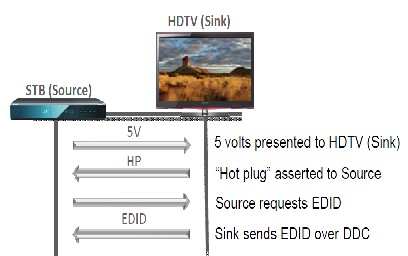
Figure 1.2- Typical EDID operation – source device (STB) and sink device (HDTV)
in the implementation of HPD signaling
2. PROBLEM STATEMENT
Display devices can have various
levels of EDID implementation and, in some cases, they may lack EDID information altogether. Such inconsistencies can cause operational issues ranging from over scan and resolution problems, to the display device not displaying the source content at all.
1. An image is shown, but the source resolution does not match that of the display.
Possible Cause- A PC cannot read the
between devices from different manufacturers. This frequently becomes an issue for professional integration, since the ability to switch digital video signals is a necessity.
3. No image is shown on the display.
Possible Cause -The source device, such as a PC graphics card, or laptop, cannot read the EDID information from the display. As a result, in some cases the PC will not output any video signal.
3. SYSTEM DESIGN Enhanced Extended Display
the user subsequently attempts to manually set the resolution to match the display, some graphics card drivers may enforce the lower default resolution and create a scrolling/panning desktop without actually changing the video resolution. By parsing the raw data from the driver by using the VESA spec and converting into readable format and transferred to the display. The user will able to know more about the display properties.
2. The display loses the image when a
new source has been selected.
Possible Cause- This is a common
occurrence with VGA sources, due to the lack of hot plug detection. While hot plug detection is supported for DVI, HDMI, and Display Port, EDID communication problems can arise from inconsistencies
capabilities of monitors. This data, which would be stored in the DTV Monitor, describes video formats that the DTV Monitor is capable of receiving and rendering. The information is supplied to the source device, over the interface, upon the request of the source device. The source device then chooses its output format, taking into account the format of the original video stream and the formats supported by the DTV Monitor. The source device (e.g., STB) is responsible for the format conversions necessary to supply video in an understandable form to the DTV Monitor.
Enhanced EDID defines a basic data structure (known as BASE EDID or block 0) of 128 bytes that all compliant displays shall supply. E-EDID also defines the rules for how EXTENSIONS may be
IJSER © 2015 http://www.ijser.org
International Journal of Scientific & Engineering Research, Volume 6, Issue 1, January-2015 1392
ISSN 2229-5518
added to the BASE structure. The
information contained within an EDID Structure, whether this is simply a BASE EDID or the combination of a BASE EDID and one or more EDID EXTENSIONS, relates to the whole display product and not individual elements of the product.
The drawing below shows this in graphical form – the BASE EDID (and any EDID EXTENSION) that is transferred from the display to the host device specifies capabilities of the combination of components and sub-assemblies contained within the display.
Fig 3.1 System Preliminary Design
SYSTEM ARCHITECTURE
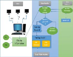
Figure 3.2 System Design
Figure 3.2 represents the system design of the project. In which the display information of the panel are received and retrieved. The key components of the diagram are User, Data Handler, and Data Interface.
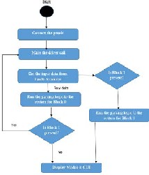
METHODOLOGY
a. Displays are connected to main system it can be any system that can connect the panel.
b. Once the displays are connected to the main system. All the displays are shown in the drop down box of the CUI or DTCM.
c. When the displays are connected then automatically the raw data is transferred to the main system.
d. For the data call, data handler
module makes the call to get the data from driver.
e. Data interface module interacts with the driver and transfers the
data to the data handler. The data handler check the data by calling
the function GetInfoData() and trace the data.
f. The data handler gets the 128bytes of data in which each byte
represent some information.
g. In these 128bytes, 1st byte represents that in the panel Block 1
is present or not. On checking the
bytes if that byte is enabled. Then again driver call is made.
h. This call again sends 128bytes of data by which user will get more
information about panel.
i. By which on parsing these next
128byte more resolution can be achieved.
j. These resolution or modes was given by CEA Extension. So, first
these modes are loaded and the process starts. The Short video
descriptors are the video descriptors, the number of
descriptor that depends on the length that we get from the 0-4 bit
of that byte.
k. After SVD, detailed descriptors
also parsed on combing these two descriptors total video modes are made.
l. These modes are displayed in
particular location of CUI. They are present inside Option and Support page. In this page inside the information page. By selecting
IJSER © 2015 http://www.ijser.org
International Journal of Scientific & Engineering Research, Volume 6, Issue 1, January-2015 1393
ISSN 2229-5518
the particular panel name the supported modes are displayed.
DATA FLOW DIAGRAM Level 0:
Figure 3.6 Activity Diagram
SEQUENCE DIAGRAM
Level 1:
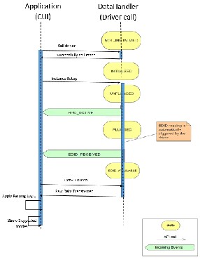
Figure 3.3 DFD level 0
Level 2:
Figure 3.4 DFD level 1
Figure 3.5 DFD level 2
ACTIVITY DIAGRAM
Figure 3.7 Sequence Diagram Opening
CUI
IJSER © 2015 http://www.ijser.org
International Journal of Scientific & Engineering Research, Volume 6, Issue 1, January-2015 1394
ISSN 2229-5518
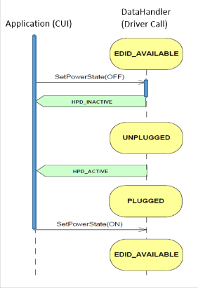
Figure 3.8 Sequence Diagram Closing CUI 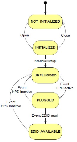
Figure 3.9 State Diagram Closing CUI
STATE DIAGRAM
Presented states have the following signification:
IJSER © 2015 http://www.ijser.org
International Journal of Scientific & Engineering Research, Volume 6, Issue 1, January-2015 1395
ISSN 2229-5518
Description
User: Once the user having more than one display, connected information about each display can be accessible by the user. User can select any display and adjust the settings by using CUI or DTCM. When the user selects any field for display information, the call is made from user side to get the values from driver, where the readable format is available in CUI display page.
Data Handler field: This is only field that interact with the driver path as well as the user. Whatever the selection or request is made from the user side it first go to data handler and then to data interface. It cannot move directly to data interface. It works like the intermediate between the driver and the user. Data handler get the data from the DI translate it into the readable format and transfer the data to the display of the page.
Data interface field: this field interact
with driver. It takes the input from the user by data handler and according to the input it will give you the values. This data may be in readable format or non-readable format. The data handler will take care of this.
4. IMPLEMENTED MODULES
4.1 CEA extension
CEA Extension includes the sink device’s ability to describe other capabilities in the E-EDID, in addition to supported video formats. For example the source device reads EDID data in the DTV Monitor to determine its capabilities and then the source device only sends what the DTV Monitor can understand. Check the Header, revision number, Check the video descriptor, and check the detailed descriptor.
The CEA Extension Header is defined as four-byte data located in the first four bytes of the EDID block. The first byte is the tag used to identify the extension. The number assigned by VESA to this tag is
02h. Following the CEA Extension Tag is the Revision Number location. The data for Revision Number was set according to which standard version the sink device was designed to support. CEA-861, CEA-
861-A, andCEA-861-B all had unique
number assignments for the Revision Number and this was used to differentiate the level of supported features, such as
”InfoPackets“, audio, etc.
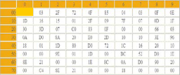
Figure 4.1 CEA Extension identification
Incrementing the version number is no longer required. CEA-861 formerly required the revision number to be set to
01h, for CEA-861-A it was 02h, and for
CEA-861-B it was 03h; however, this is no longer required in CEA-861-D, where only
03h is used. Following the Revision
Number is the Byte Number Offset. This is
used to tell where the Detailed Timing Data begins following the Reserved Data Block. The source device should use this byte offset to skip fields that it may not understand within the CEA Extension when encountering versions of this extension that may be newer than its own.
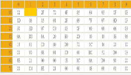
Figure 4.2 Identification of Revision
Number
CEA Extension Version 3 includes all of the fields and capabilities of Versions 1 &
2, but also includes the ability to specify any of the CEA video formats using “CEA
Short Video Descriptors.” It provides the ability for the DTV Monitor to specify
what types of advanced audio it supports
IJSER © 2015 http://www.ijser.org
International Journal of Scientific & Engineering Research, Volume 6, Issue 1, January-2015 1396
ISSN 2229-5518
using “CEA Short Audio Descriptors.” It also provides a way for the sink device to specify its speaker configuration.
4.2 Short Video Descriptor (SVD)
modes
When a Version 3 CEA Extension is provided in the DTV Monitor’s EDID
data structure, a short video descriptor shall be provided for each CEA video
format supported by the DTV Monitor. The format of the short video descriptor
shall conform to that shown in figure no
4.3. The lower 7-bits are an index
associated with the video format supported. These indexes are the same as those used in the AVI InfoFrame. All DTDs and SVDs shall be listed in order of priority; meaning that the first is the one that the display manufacturer has identified as optimal. The most significant bit declares whether the format is a native format of the display (native =1, not native
= 0). Typically, there is a single SVD, with
its native bit set. Sources should not necessarily convert video formats to a native format, but should follow recommendations for using pass-through and preferred timing.
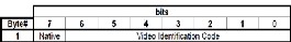
Figure 4.3 Short Video Descriptor
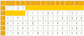
Figure 4.4 Short Video Descriptor in 128
Bytes
4.3 Detailed Timing Descriptor
The lower 4 bits of byte 3 indicates the total number of DTDs defining native formats in the whole EDID. The detailed timing section is 72 bytes in length and can be divided into four descriptor blocks,
which are each 18 bytes. In the following example, the address ranges for these four blocks are 36h-47h, 48h-59h, 5Ah-6Bh and 6Ch-7Dh. Each of these descriptors contains either detailed timing data (Detailed Timing Descriptor) or other specific types of data as described in the VESA E-EDID standard. The VESA E- EDID standard allows various descriptor sequences, combinations, or repetitions and source devices should handle descriptors that may appear in any order. The only prescribed constraint is that Detailed Timing Descriptors precede the two required Monitor Descriptors in Block
0. The descriptor requires the presence of
valid data and no fill patterns are permitted in Block 0. Therefore, the source device should handle these possibilities and requirements accordingly. Blocks used for data, not detailed timing information, have a five byte identifier header that is formatted as follows: 00h, 00h, 00h, <Tag
#>, 00h. In order to ensure YCBCR
interoperability between any two YCBCR- capable devices, a DTV monitor that supports either type of YCBCR pixel data (4:2:2 or 4:4:4) should support both types and therefore would set both bits 4 and 5 of byte 3.
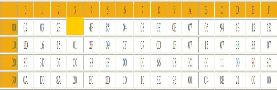
Figure 4.4 Snapshot of Identifying the
DTD modes
4.4 CODE OPTIMIZATION
The code was optimized for proper functioning, and speed of execution. This
involved removal of unnecessary variables, intermediate values that were
saved, were deleted to free memory. Similarly the code was kept generic and
simple in nature which was very helpful in losing the unnecessary lines of code.
Redundant coding was not adopted, wherever possible, use of functions helped
in abstraction, as well as in reducing the size of the source code. Some overhead
was added due to prior formatting of input
IJSER © 2015 http://www.ijser.org
International Journal of Scientific & Engineering Research, Volume 6, Issue 1, January-2015 1397
ISSN 2229-5518
and the transpose being applied to the plaintext data still the final code was small enough to merit attention.
5. CONCLUSION
Graphics driver gives display
related information such as optimal resolution, supported modes; horizontal and vertical size etc. to know about more panels EDID come into picture. EDID one driver call is made by which the system get 128 bytes of readable data. And by parsing of the data user know more about the resolutions. But sometimes EDID is not sufficient for getting the whole information about the resolution so for enhancement E-EDID which gives all resolution information about the panel. For E-EDID again the driver call is made and the system will get next 128 bytes of data. Each byte represents some information by which we know the version, detailed descriptor, short video descriptors (SVD) etc.
The number of SVD is calculated by the length i.e. the total number of video bytes. In block -0 (first 128 bytes) one byte represent the block 1 or not. By parsing each and every byte all information are gathered that helps to calculate the horizontal and vertical size with refresh rate. The combination of these three calls as supported modes.
CEA extension 861-D provides 60
resolution information which are supported by the panel. Version 1.3 of
EDID gives information that bytes having information about Block 1. For future focus EDID 1.4 is available which gives information about color characteristic so for extended purposes author incorporated this feature in the Intel Graphics card.
REFERENCES
[1] VESA E-EDID™ Standard, VESA Enhanced Extended Display Identification Data Standard, Release A, Revision 1, February 9, 2000
[2] DDWG, Digital Visual Interface,
Revision 1.0, April 2, 1999
[3] Open LVDS Display Interface (Open
LDI) Specification, Version 0.95, May 13,
1999
[4] High-Definition Multimedia Interface
Specification, Version 1.2a, December 14,
2005
[5] VESA E-DDC™ Standard, VESA
Enhanced Display Data Channel Standard, Version 1.1, March 24,
2004
[6] VESA DI-EXT, Display Information
Extension Block (DI-EXT™) for E-EDID, Release A, August 21,2001
[7] VESA E-EDID™ Implementation
Guide, VESA Enhanced Extended Display
Identification Data—Implementation
Guide, Version 1.0, June 4, 2001
[8] VESA GTF Standard, VESA Generalized Timing Formula Standard, Version 1.1, September 2, 1999.
Prof.Anuradha,G. is a faculty of school of computer science and Engineering, VIT university, Vellore. She has completed her B.E., in computer science and Engineering from Madras University and Graduation in Computer and Communication from Anna University. She has Published 5 National level papers and 2 journal publication. Her experience has a reach to students with a minimum of 8+ years.
Dr.Persis Urbana Ivy is a faculty of school of information technology and Engineering, VIT university, Vellore. Completed her research in computer science and instrumentation from Satyabhama University.
IJSER © 2015 http://www.ijser.org