International Journal of Scientific & Engineering Research, Volume 4, Issue 12, December-2013
ISSN 2229-5518
494
Experimental Investigations of the Cruciform Specimen
of GFRP16 under Biaxial Monotonic and Cyclic Loading
Dr. Muhsin J. Jweeg
Professor
Alnahrain University
Dr. Skaker S. Hasan Assistant Professor University of Technology
Yassr Y. Kahtan Assistant Lecturer Alnahrain University
Abstract
Composite materials are increasingly believed to be the materials of the future with potential for application in high performance structures. One of the reasons for that is the indication that composite materials have a rather good rating with regard to life time in fatigue. Fatigue of composite materials is a quite complex phenomenon, and the fatigue behavior of these heterogeneous materials is fundamentally different from the behavior of metals.In literature, many researches related to the biaxial fatigue experiments using tubular, bar and planar specimens can be found, the biaxial loading was achieved by using cruciform specimen with innovative mechanism.After cycling the specimens for 2000 cycles the strength reduction became more obvious. The vertical strength reduction was found to be 14.38% while the horizontal strength reduction ratio was 13.46%. Although more investigations are needed to evaluate the correct load transferred to the central gauge section of the cruciform specimen.
Introduction
In general, fatigue of fiber-reinforced composite materials is a quite complex phenomenon, and a large research effort is being spent on it today.In a fiber-reinforced composite, the damage starts very early and the extent of the damage zones grows steadily, while the damage type in these zones can change (e.g., small matrix cracks leading to large size delamination). The gradual deterioration of a fiber-reinforced composite – with a loss of stiffness in the damaged zones – leads to a continuous redistribution of stress and a reduction of stress concentrations inside a structural component. As a consequence, an appraisal of the actual state or a prediction of the final state (when and where the final failure is to be expected) requires the simulation of the complete path of successive damage states [2].
The lack of reliable multiaxial or even biaxial experimental data to validate the failure theories is the critical step in the evolution and a most efficient usage of composite materials [41]. Due to the complex anisotropic behavior of composite materials, more advanced experimental testing is needed. The current practice of using uniaxial test
IJSER © 2013 http://www.ijser.org
International Journal of Scientific & Engineering Research, Volume 4, Issue 12, December-2013
ISSN 2229-5518
495
results to predict the failure for multiaxial stress states seems inadequate. To study the mechanical behavior of fiber reinforced polymeric matrix composite laminates under static and cyclic in-plane complex stress states; a horizontal biaxial loading frame and a special cruciform type specimen have been developed.
Specimens and Experimental Setup
Due to the complex anisotropic behavior of composite materials, more advanced experimental testing is needed [3]. Multi-axial testing under complex loading conditions will improve the understanding of their mechanical behavior and allow the validation of analytical and numerical predictions.
The experimental work is presented here to accomplish many purposes; this includes the manufacturing of a rig or mechanism that can perform planar biaxial loading, the composite materials laminates, preparation of the required specimens, investigation of their mechanical properties, fatigue behavior under uniaxial and plane biaxial loading.
There is no standard shape or design for the biaxial specimens until now [4], so the specimen design was based on the generic form shown in Figure (1), with specimen arms
all of the same length and a circular central gauge section.
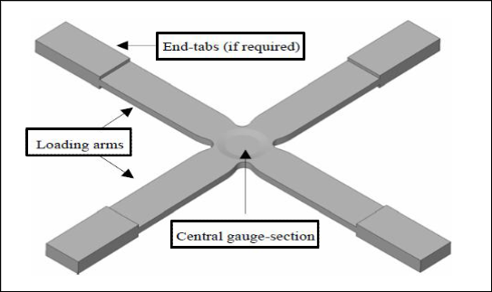
Figure (1) The general shape for planar biaxial specimen (cruciform).
IJSER © 2013 http://www.ijser.org
International Journal of Scientific & Engineering Research, Volume 4, Issue 12, December-2013
ISSN 2229-5518
496
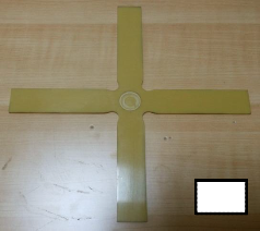
The specimens were made from GFRP (fiber glass reinforced polymer) ready prepreg of 16 woven layers stacked as [0/90]8. The central zone was milled away [5] to a constant depth of 1 mm for each side and the tapered edges were eliminated. The specimens were cut from the composite plate of (50*40 cm) using a CNC machine giving them the final
exact shape of 220 mm in length, as shown in figure (2).
Central
(a) (b)
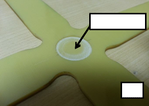
Figure (2) The manufactured and final cut cruciform specimen, (a) Central milled section, (b) The overall specimen.
The biaxial mechanism was designed and manufactured to perform biaxial static and fatigue tests on a regular universal testing machine. The biaxial mechanism can perform four different stretching ratios (1:1, 1:2, 1:3 and 1:4) according to the angle of the
inclined shafts; the mechanism is shown in figure (3).
Movable
upper
Fixed lower
(a)
(b The
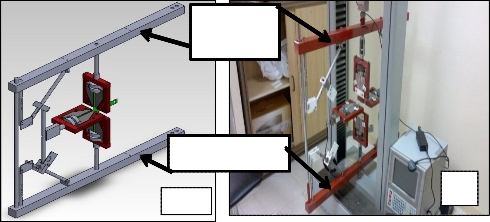
Figure (3) The Biaxial3 mechanism, (a) designed, (b) finished.
IJSER © 2013 http://www.ijser.org
International Journal of Scientific & Engineering Research, Volume 4, Issue 12, December-2013
ISSN 2229-5518
497
Results and Discussion
The cruciform specimens were tested under static biaxial loading of 1:1 ratio. The central gauge section was reduced by 1 mm (an approximate value) from each side to ensure the failure in the central section. Figure (4) shows the failure of the cruciform specimen in the central section which is different than that shown in figure (5) which
shows the arm breaking (premature failure).
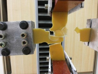
Figure (4) Cruciform specimen at failure after biaxial tensile test of stretch ratio 1:1.
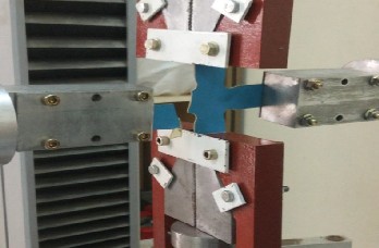
Figure (5) The plastic cruciform specimen premature failure
(arm breaking without central reduction section).
IJSER © 2013 http://www.ijser.org
International Journal of Scientific & Engineering Research, Volume 4, Issue 12, December-2013
ISSN 2229-5518
498
Figures (6), (7), and (8) show the results of the biaxial test, they are configured as force – time diagram rather than force – displacement diagram because the horizontal load cell interface can provide the load with time. The horizontal load cell recording data rate is 11 readings per second while the vertical load cell provides 13 readings per second. The three figures show that the cruciform specimen had greater strength than the uniaxial specimen, this cannot be suggested as the cruciform specimen is stronger than the uniaxial because the stress calculating in the biaxial gauge section is not straight forward. This is due to the fact that a cruciform specimen contains loading arms that are common to two independent loading axes. This situation can result in a proportion of the load in each direction bypassing the gauge section and being reacted by the material
surrounding the gauge section [5].
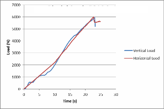
Figure (6) FIorce –Jtime diagSram for
biaxial GFRP16 (specimen1) with
loading ratio 1:1.
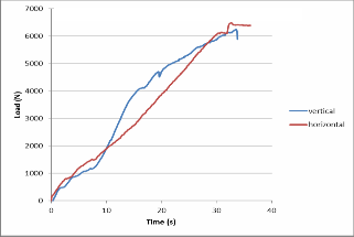
EFigurRe (7) Force – time diagram for
biaxial GFRP16 (specimen2) with
loading ratio 1:1.
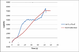
Figure (8) Force – time diagram for biaxial GFRP16 (specimen3) with loading ratio 1:1.
IJSER © 2013 http://www.ijser.org
International Journal of Scientific & Engineering Research, Volume 4, Issue 12, December-2013
ISSN 2229-5518
499
The specimens of GFRP16 were subjected to cyclic tests of similar loading ratio but with 1000 cycles and 2000 cycles.Figures (9), (10), and (11) show the biaxial tensile test after cycling the specimens into 1000 cycles. The behaviors of the specimens were similar to those tested without cycles and very little change in the strength was noticed unlike the uniaxial specimens. The load variation between the vertical and horizontal directions was very little and it was calculated from the data and found to be 2.7%. The strength reduction in the vertical directions was noticed to be greater than horizontal
direction. It was 3.8% while only 0.56% in the horizontal direction.
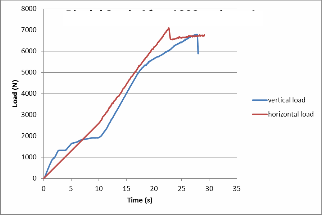
Figure (9) Force – time diagram for biaxial
GFRP16 (specimen1) after 1000 cycles with
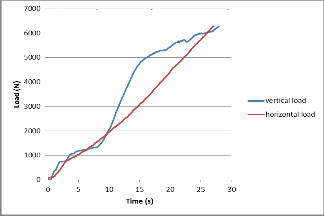
Figure (10) Force – time diagram for biaxial GFRP16 (specimen2) after 1000
loading ratio 1:1.
cycles with loading ratio 1:1.
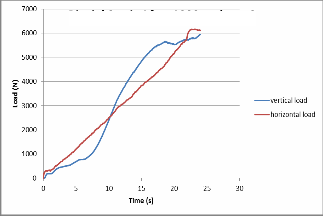
Figure (11) Force – time diagram for biaxial GFRP16 (specimen3) after 1000
cycles with loading ratio 1:1.
IJSER © 2013 http://www.ijser.org
International Journal of Scientific & Engineering Research, Volume 4, Issue 12, December-2013
ISSN 2229-5518
500
After cycling the specimens for 2000 cycles the strength reduction became more obvious as can be shown from figures (12), (13) and (14). The vertical strength reduction was found to be 14.38% while the horizontal strength reduction ratio was 13.46%. this results differs from the first set results (1000 cycles) in which the damage begins effect of the strength after the 1000 cycles meanwhile for the uniaxial test the damage started sooner (at 500 cycles) for the same loading ratio. Although more investigations are needed to evaluate the correct load transferred to the central gauge section of the
cruciform specimen.
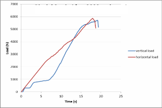
Figure (12) Force – time diagram for biaxial GFRP16 (specimen1) after 2000
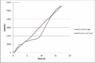
Figure (13) Force – time diagram for biaxial GFRP16 (specimen2) after 2000
cycles with loading ratio 1:1.
cycles with loading ratio 1:1.
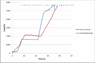
Figure (14) Force – time diagram for biaxial GFRP16 (specimen3) after 2000
cycles with loading ratio 1:1.
IJSER © 2013 http://www.ijser.org
International Journal of Scientific & Engineering Research, Volume 4, Issue 12, December-2013
ISSN 2229-5518
501
Conclusions
The biaxial mechanism is proven to compensate for the sophisticated biaxial testing machines with reasonable cost and possibilities. It can perform static and fatigue tests with multiple stretching ratios (1:1, 1:2, 1:3 and 1:4). The loadings directions are not limited to tension – tension only but to tension – compression as well.
From the fatigue experimental tests results, it is concluded that the fatigue damage occur in very early stage of the loading history that was proven by the strength reduction of the uniaxial loaded specimens after 500 cycles only and the biaxial loaded specimens after 2000 cycles only under strain controlled of (R=0.2). The percentage reduction was (18.37%) for GFRP16 after 500 cycles and between (13.46%-14.38%) for the biaxial loaded specimens after 2000 cycles.
The cruciform specimens shape is a major parameter in obtaining a valid biaxial test result. It is concluded, from the experimental results, that a reduction of the thickness in the central gauge section is enhancing the start of the failure in the center of the specimens and preventing the premature failure (the arms breaking).

References
1. Talreja R., “Fatigue of composite materials”, Technomic Publishing Company,
Inc. USA, 1987.
2. Degrieck, J. and Van Paepegem, W., Fatigue Damage Modeling of Fiber- Reinforced Composite Materials: Review, Applied Mechanics Reviews, 54(4), pp. 279-300, 2001.
3. A. Makris, C. Ramault, D. Van Hemelrijck , E. Lamkanfi and W. Van Paepegem, “Biaxial Mechanical Fatigue using Cruciform Composite Specimens”, Proc. of the 13th European Conference on Composite Materials, Stockholm, 2008.
4. Hodgkinson J. M., “Mechanical testing of advanced fiber composites”, Woodhead
Publishing Ltd and CRC Press LLC, 2000.
5. M. R. L. Gower and R. M. Shaw, “Towards a Planar Cruciform Specimen for Biaxial Characterization of Polymer Matrix Composites (PMCs)”, NPL Measurement Note Report 09, 2009.
IJSER © 2013 http://www.ijser.org