International Journal of Scientific & Engineering Research, Volume 4, Issue 1Ř, mber-2013
ISSN 2229-5518
Exergy and Efficiency Analysis of Combined
Cycle Power Plant
Padma Dhar Garg*, Satender Dehiya*, Ankit Barasiya**, Aditya Rahangdale**, Vijay Shankar Kumawat***
*M.Tech Student, Malaviya National Institute of Technology Jaipur, Rajasthan, India
**M.Tech Student, UIT, Rajeev Gandhi Proudyogiki Vishwavidyalaya Bhopal, Madhya Pradesh, India
***Assistant Professor, Manipal University Jaipur, Rajasthan, India
1161
Abstract— Combined cycle power plants with a gas turbine topping cycle and steam turbine bottoming cycle are widely used due to their high energy efficiencies. Combined cycle cogeneration has the possibility to produce power and process heat more efficiently, leading to higher performance and reduced greenhouse gas emissions. The objective of the present work is to evaluate the performance of a combined cycle cogeneration configuration based on energy and exergy analyses approaches. The effect of operating conditions on combined cycle efficiency, combined cycle cogeneration efficiency, power outputs and exergy destruction are investigated. The operating conditions investigated include gas turbine pressure ratio, gas turbine inlet temperature, process heat load and ambient conditions. It is demonstrated that a combined cycle cogeneration unit, operates more efficiently and produces less carbon dioxide than two separate, power production and process heat systems. The exergy analysis identifies the sources of irreversibility in the system and aids in the evaluation of losses and outputs by examining their quality. Exergy analysis of the combined Brayton/Rankine power cycle of NTPC (National Thermal Power Corporation) Dadri India is done. Theoretical exergy analysis is carried out for different combined cycle power plant which consists of a gas turbine unit, heat recovery steam generator without extra fuel consumption and steam turbine unit. The results pinpoint that more exergy losses occurred in the gas turbine combustion chamber reaching 35% of the total exergy losses, while the exergy losses in the other plant components are between 7% and 21% of the total exergy losses at 1400°C turbine inlet temperature and pressure ratio 10. The paper also considered the effect of the pressure ratio, turbine inlet temperature, pressure drop in combustion chamber and heat recovery steam generator on the exergy losses in the plant. Significant exergy loss is observed on changing pressure ratio and inlet temperature.
Index Terms— Exergy Analysis, Combined Cycle Power Plant, Efficiency Analysis, Exergy Destruction, First Law Efficiency, Second Law Efficiency, Irreversibility.
1 INTRODUCTION
—————————— ——————————
India is a rapidly developing economy, with a need for relia- ble and efficient supply of electricity and to be a power suffi- cient country is one of its prime concerns. The present in- stalled capacity of electricity in India is 147,402.21MW which gives the per capita consumption of power in 2009-10 as calcu- lated by the Central Electricity Authority about 720 kWh. While the per capita consumption of power in developed countries like U.S. is 13,338 kWh. The National Electricity Poli- cy envisages that the per capita availability of electricity will be increased to over 1000 units by 2012. So large number of new power projects are currently in progress. Thermal power plants account for 75% of the installed capacity and gas power plant accounts 10% of the total power capacity of India. Be- cause of this higher efficiency gas turbine and combined cycle power plants are becoming more and more attractive with regard to reduced fuel consumption and less emissions. As many as 56 thermal power stations in the country were left with a critical coal stock of less than seven days at the end of October 2008. High generation, inadequate linkages and most importantly insufficient coal supply were the major reasons behind the critical stock of coal at these power stations. In Sin- grauli region, there are many power plants like LNCO power
1320MW, ESSAR power 1200MW and NTPS Vindhyachal
which are suffering due to coal crises. NCL (CIL) stopped supplying coal to LANCO power and ESSAR power. In west- ern region Korba (CG) and Dahanu (Maharastra) stations re- ceived coal supply of only 77 percent of their linkages, the Chandrapur and Khaperkheda II (Maharastra) stations had insufficient linkage. The Ennore (North Chennai) and Mettur power stations in south received coal supply of 64 percent, 66 percent and 75 percent of their linkages, respectively. Kotha- gudem (AP) station suffered due to high generation and in- adequate linkage. Coal supply to the Kahalgaon (Bihar) and Farakka station in the eastern region received only 69 percent and 62 percent of their linkage respectively. IB Valley (Orissa), Talcher TPS, Tenughat (Bokaro) and Budge plants suffered due to insufficient linkages.
A basic gas turbine cogeneration system consists of a gas tur- bine cycle (compressor, combustion chamber and expander), a heat recovery system for steam production and steam turbine. Fuel is introduced into the combustion chamber of the gas turbine where combustion takes place with compressed air coming out from the compressor. Hot exhaust gases from the gas turbine are the waste heat sources for process heat produc- tion. The quantity and quality of process heat produced de- pend on the temperature of the hot exhaust gases entering the
IJSER © 2013 http://www.ijser.org
International Journal of Scientific & Engineering Research Volume 4, Issue 1Řǰȱ ȬŘŖŗřȱ
ISSN 2229-5518
1162
heat recovery system and the resulting temperature of the steam produced. Steam produced can be used either for process heat or electric power that is generated by a steam turbine. Dadri power plant (NTPC), steam is used for power production. To sum up, Dadri power plant is based on gas turbine electric power production by steam turbine. NTPC (National Thermal Power Corporation) was set up in the pub- lic sector in the 1975. Only PSU (Public Sector Unit) to achieve excellent rating in respect of MOU (Millions of Unit) targets signed with Government of India each year. Today NTPC con- tributes more than 3/5th of the total power generation in In- dia. The schematic diagram of NTPC Dadri (Gas Unit) com- bined power cycle is shown in figure 1. The gas turbine (Sie- mens AG, Germany, V 94.2, 131.3 MW) is shown as a topping plant, which forms the high temperature loop, whereas the steam plant (BHEL India, 146.5 MW, two cylinder condensing reaction 2x22 number of stages HP) forms the low temperature loop.The connecting link between the two cycles is the heat recovery steam generator (BHEL Trichy, Vertical forced Circu- lation) working on the exhaust of the gas turbine. A gas tur- bine cycle consists of an air compressor (Siemens KWU, Type Multistage Axial Flow, Number of stages: 16), a combustion chamber (Vertical Silo Type) and a gas turbine. The turbine’s exhaust-gas goes to a heat-recovery steam generator to gener-
ate superheated steam. That steam is utilized in a standard
2 EXERGY ANALYSIS
Exergy is a generic term for a group of concept that defines the maximum possible work potential of a system. In an open flow system there are three types of energy transfers across the control surface namely working transfer, heat transfer and energy associated with mass transfer and /or flow. The work transfer is equivalent to maximum work which can be ob- tained from that form of energy. The exergy of heat transfer (Q) from the control surface at temperature T is determined from maximum rate of conversion of thermal energy to work Wmax is given by:
Wmax = Q (1 − TO /T)
Exergy is defined as the maximum work that may be achieved
by bringing a system into equilibrium with its environment.
Exergy analysis is a method that uses the conservation of mass
and conservation of energy principles together with the
second law of thermodynamics for the analysis, design and
improvement of energy systems. Exergy analysis is based on
both first and second law of thermodynamics. Exergy analysis
can clearly indicate the location of energy degradation in a
process. The exergy method is a useful tool for furthering the
goal of more efficient energy resource use, for it enables the
locations, types and magnitudes of wastes and losses to be
IJSER
steam power cycle, which consists of a turbine, a condenser
(BHEL, Rectangular, SCD-1200) and a pump (BHEL Hydera-
bad, Vertical Mixed Flow). Both the gas and steam turbines
drive electric generators.

determined. Many engineers and scientists suggest that the thermodynamic performance of a process is best evaluated by performing an exergy analysis in place of conventional energy analysis because exergy analysis appears to provide more in- sights and to be more useful in furthering efficiency improve- ment efforts than energy analysis. The main purpose of exergy analysis is to identify the causes, types, location and to calcu- late magnitude of thermal losses.
3 EXERGY ANALYSIS CALCULATION
Energy analysis is based on first law of thermodynamics, which is related to the conservation of energy. While exergy analysis is based on second law of thermodynamics which state the conservation of mass and degradation of the quality of energy along with the entropy generation in the analysis design and improvement of energy systems. The second law analysis, i.e. the exergy analysis, calculates the system perfor- mance based on exergy, which is defined as the maximum possible reversible work obtainable in bringing the state of the system to equilibrium with that of environment. In the ab- sence of magnetic, electrical, nuclear, surface tension effects, and considering that the system is at rest relative to the envi- ronment, the total exergy of a system can be divided into two components: physical exergy and chemical exergy.
The second law efficiency is defined as:

η2nd = actual thermal
efficiency
maximum possible thermal efficiency
Fig. 1 Schematic diagram of NTPC Dadri.
IJSER © 2013 http://www.ijser.org
International Journal of Scientific & Engineering Research Volume 4, Issue 1Řǰȱ ȬŘŖŗřȱ
ISSN 2229-5518
1163
A combined cycle power plant as shown in figure 2(a & b) includes both the brayton cycle and rankine cycle. It joins operation of the gas turbine at the “hot end” and the steam turbine at the cold end. As shown in the diagram 2(b),which is operating temperature and entropy diagram, gas turbine operates on the brayton cycle, i.e., intake air compressed nearly isentropically from point 5 to 6, combusted at constant pressure from point 6 to 7, and then expanded nearly isentropically in the gas turbine from 7 to 8, exhausting gas from point 8, the brayton cycle applied to gas turbine is an open cycle , temperature at point 8 is higher than 1000°C and does not form a closed loop with the inlet air of point 1.[1]
for the process and To is the temperature of environment.
[2][1]. The first part of the above mentioned equation
represents the energy of the process heat which is:
Qp = m(hi − ho ) (4)
The process heat generator (HRSG) consists usually of three
main parts an economizer, an evaporator and the last is
superheater, all working at a process heat pressure. The water
at Tc enters the economizer and exits at Tf at saturated liquid state. The saturated liquid enters the evaporator and exits at
the same temperature at saturated vapor state; finally the saturated steam enters the superheater and exits at superheat temperature. [2][13] Energy balance at the system consisting of superheater and evaporator is:
m(h − hf ) = ma (1 + rfa )(ht − hpp ) (5)
Where ma is the mass of air in the gas turbine engine, rfa is the
fuel air ratio used in the combustion process, ht is the enthalpy of gas mixture at turbine exit, and hpp is the enthalpy of gas
mixture at pinch point temperature. [13] To have a better as- sessment, some useful ratios such as process heat exergy factor and power to heat ratio are defined as: [2]


BP
p QP

IJSERr = WE For simple cycle,
(6)
(a) (b)
Where, WE and QP are electrical energy in (kJ) or (kWh) and
thermal energy of process heat respectively.
WE
Fig. 2(a & b) T-S diagram of combined cycle power plant.

rph = l
P
For combined cycle,
The useful products of a CCPP are electrical energy, WE the
thermal energy, QP in the form of superheated steam. The thermodynamics performance is the based on the first law
efficiency and is defined as:
WE+QP
Where, Q′P = QP − WST , WST is electrical energy of steam tur-
bine in (kJ) or (kWh).
Exergy is essential concept in second law analysis. If less exer- gy is consumed, a cycle can produce more efficiency. There-

ηlst =
F
(1)
fore, by using exergy to evaluate the power plant cycles, a more accurate performance of system can be obtained. The
For simple cycle WE is equal to WGT and for combined cycle
WE is equal to WGT + WST. Actually the efficiency of a CCPP is reduced by the various inherent losses. One unavoidable loss
is heat lost by radiation and convection, while a second is the internal loss caused by irreversible processes as discussed in the second law of thermodynamics.
The exergy of the steam / water is defined as: [2]
ε = m(h − TO s) (2)
Where ε is exergy, h is enthalpy, To (K) is the ambient temper-
ature and s is the entropy (kJ/kg K).The exergy of steam/ wa-
ter produced is:
Bp = m[(hi − ho ) − To (si − so )] (3)
Where m is the mass of steam /water, si is the entropy of inlet
condition for the process, so is the entropy of outlet condition
exergy factor of generated steam / water (εs ) and the exergy factor of fuel input (εf ) can be expressed as follows: [2]

ε = BP
s
QP

ε = Bf = 1
F
Qf

η2nd = ∗ [(r + εs )/(r + 1)] (7)
4 EFFICIENCY OF COMPONENTS OF POWER PLANT
Compressor efficiency, superheater efficiency and economizer efficiency of gas turbine of combined cycle is given by follow- ing equation which is taken from NTPC technical directory. [20]
IJSER © 2013 http://www.ijser.org
International Journal of Scientific & Engineering Research Volume 4, Issue 1Řǰȱ ȬŘŖŗřȱ
ISSN 2229-5518
1164
ϒ-l

2 ϒ
∗ ϒ − 1
Tinst = CinT ∗ P
Pl

R g = Cpg ϒ

Tinst − Tci
Compressor Efficiency = η =
Tco − Tci
∗ 100
5.2 HRSG: - The exergy loss due to irreversibility in heat re-
covery steam generator is given by:
ΔS = T [m(s
− s ) + m (s
− s )]
His-Hos
* 100
IHRSG = TO∗ O O a e
g 6 4

Superheater Efficiency = η = m∗Cp ∗(Tis
-Tos)

IHRSG = CPG ∗ ln T
− R g

∗ ln P6

Economiser Efficiency = η = Hie − Hoe
m ∗ Cp ∗ (Tie − Toe )
∗ 100
T4 P4
5 EXERGY DESTRUCTION AND EXERGY LOSS
Exergy is only conserved for reversible process but partially consumed in an irreversible process. Thus, exergy is never in balance for real processes, it is a measure of quality and quan- tity of energy. For real process the exergy input always ex- ceeds the exergy output. This imbalance is due to irreversibili- ty which is called exergy destruction. Unlike energy, exergy is not conserved but it is destroyed by irreversibility within sys- tem. This irreversibility may be classified as internal and ex- ternal irreversibility. Main sources of internal irreversibility are friction, unrestrained expansion, and chemical reaction. External irreversibility arises due to heat transfer through a
5.3 Steam Turbine (ST):- The exergy loss due to irreversibil-
ity in steam turbine is given by:
IST = ms ∗ (sb − sa ) ∗ TO
Since isentropic efficiency of ST is,

η = ha − hb
ha − hbs
hb = hf + xb ∗ hfg
sb = sf + xb ∗ sfg
IJSER
finite temperature difference. Exergy is lost when the energy
associated with a material or energy stream is rejected to the
environment. [10][3][17]
5.4 Exhaust Loss:- The exergy loss due to irreversibility in exhaust is given by:
To


Iexh = 1 − T dQ = mg ∗ Cpg (T6 − TO ) − TO ln T
O 6
T TO
T6
5.5 Compressor: - The exergy loss due to irreversibility in
compressor is given by:
IC = ma ∗ (s2 − sl ) ∗ TO


T2 P2
(s2 − sl ) = Cpa ln Tl a ln P
R a = Cpa ∗

ϒ − 1
ϒ
Fig. 3 Temperature entropy diagram of brayton
/rankinecombuned cycle power plant.
5.1 Gas Turbine (GT):- Exergy loss due to irreversibility in
Where T1 is compressor inlet temperature in GT and T2 is compressor outlet temperature in gas turbine (in K).
5.6 Combustion Chamber (CC):-The exergy loss due to irreversibility in combustion chamber is given by:
gas turbine is given by:
ICC = TO mg Cpg ln T
− mg R g ln P − m cp ln T
− ma R a ln P
IGT = mg ∗ TO ∗ (s4 − s3 )


3 3 2 2
a
TO PO Tl Pl

where(S4 − S3 ) = Cpg ln T
T3
− R g

P4
ln P3
5.7 Total Exergy Destruction:-
ITOTAL = IC + ICOMB + IGT + IHRSG + IST + IEXH
IJSER © 2013 http://www.ijser.org
International Journal of Scientific & Engineering Research Volume 4, Issue 1Řǰȱ ȬŘŖŗřȱ
ISSN 2229-5518
1165
η
ically. Exergy loss due to irreversibility in different compo- nents of gas/steam combined power cycle is shown graphical- ly.
6.1 Compressor Pressure Efficiency
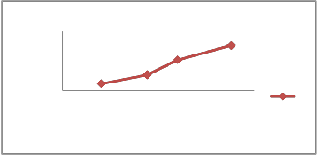
This graph shows variation of compressor efficiency with re- spect to compressor pressure ratio. In Dadri plant compres- sor ratio is varied between 8 to 10 as compressor ratio increas- es, efficiency of compressor also increases.
56 η
292 293 294 295 296 297
Flue gas temperature, °C
6.4 GT Efficiency Variation w.r.t Environment Tempera- ture
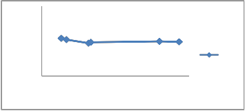
This graph shows variation of efficiency of gas turbine w.r.t environment temperature in °C. Gas turbine efficiency of combined cycle power plant Dadri is about 35% to 40% level.
95 η
85
75
40
38
36
η 34
32
GT…
IJSER
8.5 9 9.5 10 10.5
Compressor pressure ratio
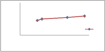
6.2 HP Superheater Efficiency Variation
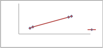
This graph shows variation of efficiency w.r.t flue gas temper- ature. Superheater efficiency increases by increasing input steam pressure and input flue gas temperature. HP Superhea- ter efficiency of HSRG of Dadri power plant is around 62% to
63%.
30
0 10 20 30
Enviornment temperature, °C
6.5 ST Efficiency Variation w.r.t Environment Tempera- ture
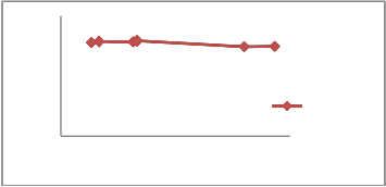
This graph shows variation of efficiency of steam turbine w.r.t environment temperature in ˚C steam turbine efficiency of combined cycle power plant Dadri is about 25% to 30% level
64 η 30
62
η
60
558 560 562 564
Inlet flue gas temperature ,°C
20
10
0
0 10 20 30
Environment temperature ,˚C
ST Efficiency
6.3 HP Economizer Efficiency Variation
This graph shows the variation of efficiency w.r.t inlet flue gas temperature. In NTPC Dadri HP economizer efficiency varies between 56% to 59%. As inlet flue gas temperature increases with low steam pressure, efficiency of HP economizer also increases.
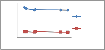
6.6 First Law and Second Law Efficiency Variation of
CCPP
First law efficiency in the current investigation comes out to be
45%. This indicates that plant is producing energy by using
45% of fuel but in real it is not true because first law tells only
about capabilities of power plant which it can attain. Howev-
er, when the same is calculated with the help of 2nd law, qual-
ity of energy is known. It means that if our second law effi-
IJSER © 2013 http://www.ijser.org
International Journal of Scientific & Engineering Research Volume 4, Issue 1Řǰȱ ȬŘŖŗřȱ
ISSN 2229-5518
1166
ciency is high, we can use the efficiency more qualitatively. Losses will low and less heat will be dissipated to the atmos- phere. For Dadri power plant, second law efficiency is around
24%. To improve second law efficiency, HRSG unit’s capacity can be increased by using economizer. More energy thus com- ing out from exhaust gas can be extracted for steam turbine.
100
1173
1273
1373
1473
1573
0
0 5 10 15
Compressor pressure ratio
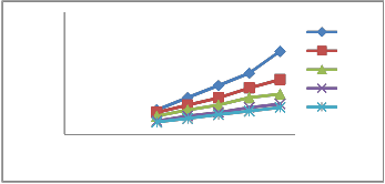
6.9 Graph of Exergy Loss in Steam Turbine at Different
TIT
Graph shows the variation of exergy loss in steam turbine with variation in compressor pressure ratio and turbine inlet temperature. At low turbine inlet temperature (900˚C) the ex- ergy loss in the steam turbine is lower and as the turbine inlet temperature (1400˚C) increases, the exergy loss is increasing rapidly. There is similar pattern in exergy losses that can be seen at temperature 1000 to 1400˚C but at low turbine inlet temperature, the pattern is slightly different. At any particular turbine inlet temperature as the compressor pressure ratio increases the exergy loss decreases slowly. In steam turbine
5% to 15% exergy loss is calculated.
50
45
6.7 Graph Showing Exergy Loss in HRSG at Different
TIT
Graph is plotted between exergy loss and compressor pressure ratio in a heat recovery steam generator for varying turbine inlet temperature. As pressure ratio increases, the gas turbine exhaust temperature decreases and thereby decrease in exergy destruction in WHRB. In HRSG 15% to 31% of exergy loss is
40
35
30
25
20
0 10 20 30
Enviornment temperature , °C
First law
Efficiency
Second law
Efficiency
calculated.
IJSER
40
30
20
10
0
0 5 10 15
Compressor pressure ratio
1673
1573
1473
1373
1273
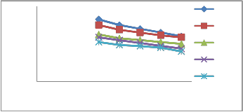
6.10 Graph of exergy loss in combustion chamber at
different TIT
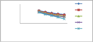
Graph shows the variation of exergy loss in combustion chamber with variation in compressor pressure ratio and tur- bine inlet temperature. As pressure ratio increases, mass flow rate of air decreases so exergy destruction rate also decreases. At any particular turbine inlet temperature as the compressor pressure ratio increases the exergy loss decreases. In combus- tion chamber 35% to 50% of exergy loss is calculated.
6.8 Graph Showing Exergy Loss in Gas Turbine at Dif- ferent TIT
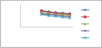
Graph shows the variation of exergy loss in gas turbine with variation in compressor pressure ratio and turbine inlet tem- perature. As pressure ratio increases, the exergy destruction in the turbine for all cases increases, because the entropy at tur- bine inlet decreases. In gas turbine, 2-7% of exergy loss is cal- culated.
80
150
100
50
0
0 5 10 15
Compressor pressure ratio
1573
1473
1373
1273
1173
60
40
20
0
0 5 10 15
Compressor pressure ratio
1673
1573
1473
1373
1273
7. CONCLUSION
For Dadri power plant, the first law efficiency is around 45% and that associated with second law is 24%. NTPC Dadri can use 45% of its energy source to convert to real work. The rest is consumed by system losses and irreversibility.
IJSER © 2013 http://www.ijser.org
International Journal of Scientific & Engineering Research Volume 4, Issue 1Řǰȱ ȬŘŖŗřȱ
ISSN 2229-5518
1167
To improve combined cycle power plant efficiency:-
1. The gas turbines are major power producer so it is essen- tial to improve the efficiency of gas turbine.
2. Heat recovery steam generators are the main equipment for combined cycle power plant. Therefore, proper design- ing of HRSG is required to use all energy coming from exhaust gases.
3. More exergy losses occur in the combustion chamber due to combustion irreversibility and this must be reduced with the aid of new advances in the technology.
4. At higher turbine inlet temperature and lower pressure ratio, the exergy losses in the combustion chamber, heat recovery steam generator and steam turbine are higher.
5. At lower turbine inlet temperature and higher pressure ratio the exergy losses in the gas turbine is higher.
ACKNOWLEDGEMENT
Special thanks go to AGMP. K. Mishra NTPC Dadri, AGM A.K. Dutta NTPC Dadri and System engineer Mr. Vishal Jatav
[8] A.Khaliq, S.C. Kaushik, “Second-law based thermodynamic analysis of Brayton/Rankine combined power cycle with reheat”, Centre for Energy Studies, Indian Institute of Technology.
[9] Wenguo Xiang, “Performance Improvement of Combined Cycle- Power Plant Based on the Optimization of the Bottom Cycle and Heat Recuperation”Journal of Thermal Science Vol.16, No.1 84―89.
[10] Mustafa ZekiYilmazo and EhsanAmirabedin, “Second law and sen- sitivity analysis of a combined cycle power plant in tur- key”IsıBilimiveTekniğiDergisi, 31,2, 41-50, 2011 J. of Thermal Science and Technology.
[11] A.G. Memon, K. Harijan, S. F. Shah, R.A. Memon and M. A. Uqaily,
“Exergy Analysis of 144 Mw Combined Cycle Power Plant KotriPa- kistan”Sindh Univ. Res. Jour. (Sci. Ser.) Vol.45 (1):107-112 (2013).
[12] S. M. Sami, “Energy and exergy analysis of an efficient organic Ran- kine cycle for low temperature power generation” International Journal of Ambient Energy, Volume 29, Number 1 January 2008.
[13] Zaili Zhao, Zhaofeng Yuan, Qinghua Cui and Na Yan, “Exergy
Analysis of an WGZ220/6.8-1 Type Alkali Recovery Boiler” Modern applied science Vol.4, No. 2 February 2010.
IJSER
NTPC Dadri who has provided data for combined cycle pow-
er plant.
REFERENCES
[1] S.C. Kaushik, V.Siva Reddy and S.K.Tyagi, “Energy and exergy ana- lyses of thermal power plants” Renewable and Sustainable Energy Reviews 15 (2011) 1857–1872.
[2] E.Bilgen,“Exergetic and engineering analysis of gas turbine based cogeneration systems” Energy 25 (2000)1215-1229.
[3] Nikhil Dev and Rajesh Attri “Exergetic analysis of combustion chamber of a combined heat and power system” Proceedings of the National Conference on Trends and Advances in Mechanical Engi- neering, YMCA University of Science & Technology, Faridabad, Ha- ryana, Oct 19-20, 2012.
[4] A.K.Tiwari, Mohd Islam and M.N.Khan,“Thermodynamic Analysis of Combined CyclePowerPlant”International Journal of Engineering Science and Technology Vol. 2(4), 2010, 480-491.
[5] Calculation of thermodynamic property of wa-
terhttp://www.peacesoftware.de/einigewerte/wasser_dampf_e.ht ml.
[6] Murad A. Rahim, EhsanAmirabedin and HüseyinTopal, “Exergetic analysis of heat recovery steam Generator in a cobined cycle power plant”.
[7] Nag P. K., 2004, “Power Plant Engineering” Tata McGraw-Hill Publi-
cation company Limited, New Delhi, Second Edition.
[14] Nikhil Dev, Samsher, S. S. Kachhwahan and Rajesh Attri , “A review
of combined cycle power plant thermodynamic cycles”Proceedings of the National Conference on Trends and Advances in Mechanical Engineering, YMCA University of Science & Technology, Faridabad, Haryana, Oct 19-20, 2013.
IJSER © 2013 http://www.ijser.org
International Journal of Scientific & Engineering Research Volume 4, Issue 1Řǰȱ ȬŘŖŗřȱ
ISSN 2229-5518
1168
Table 1 Compressor efficiency analysis of gas turbine.
IJSER
IJSER © 2013 http://www.ijser.org
International Journal of Scientific & Engineering Research Volume 4, Issue 1Řǰȱ ȬŘŖŗřȱ
ISSN 2229-5518
1169
Table 2 Exergy and efficiency analysis of component of heat recovery steam generator.
Equipment | | Mfg(kg/s) | Ms(kg/s) | P | ° T C (fg) | ° T C (st) | h(kj/kg) | H (kW) | s(kj/kg.K) | ε | Mfg*Cp*ΔT | η (%) |
HP- Superheater | I | 471.59 | 61.75 | 66 | 559.5 | 281.5 | 2777.42 | 171505.7 | 5.83 | 1028.4 | 70370.6598 | 62.28031 |
HP- Superheater | O | 471.59 | 61.75 | 65 | 476.6 | 530.1 | 3487.17 | 215332.7 | 6.92 | 1411.2 | 70370.6598 | 62.28031 |
HP- Economizer | I | 471.59 | 61.75 | 100 | 294.1 | 156.9 | 663.91 | 40996.4 | 1.89 | 96.91 | 60948.2916 | 57.04968 |
HP- Economizer | O | 471.59 | 61.75 | 97 | 222.3 | 281.3 | 1227.43 | 75767.2 | 3.06 | 309.3 | 60948.2916 | 57.04968 |
ITJable 3 Exergy anSalysis for steam cycleEof combined cycle powRer plant.
IJSER © 2013 http://www.ijser.org


