International Journal of Scientific & Engineering Research, Volume 4, Issue 12, December-2013 931
ISSN 2229-5518
Evaluation of Chezy Coefficient on Concrete Trapezoidal Channel Strengthened By CFRP Sheets
First Author, Second Author
ABSTRACT_ Carbon fibe r reinforce d polymers (CFRP) were wide ly used in strengthening reinforced concrete members in the last few years due to advantageous properties such as light weight, corrosion resistance, and smooth surface and high strength. This study is to investigate the flexural behavior of reinforced concrete trapezoidal channels strengthened with CFRP sheets inside the channel, and evaluate the effect of CFRP sheets on the flow, especially on Chezy coefficient with different discharges. The research is conducted using four specimens of trapezoidal channels. It is 45 cm bottom wide, 40cm depth, 60˚ side slope and the length is 160 cm depending on the best hydraulic section for trapezoidal channel. the channels are linked together to be flume with length (6.4m) and then three different cases of channels are investigated with five different discharges to find the Chezy coefficient for each case. From experimental data and curvatures found that Chezy coefficient (c) is increased with increasing ratio of CFRP sheets to concrete. Finally, a series of flexural tests were conducted on reinforced concrete channels. One is controlled channel and other three channels were strengthened. We found that the externally bonde d CFRP sheets have increased the stiffness and maximum load of the channels and the cracks and the deflections have decreased for strengthened channels.
Index Terms— strengthening, CFRP sheets open channels, trapezoidal, Chezy coefficient, concrete
—————————— ——————————
1 INTRODUCTIONI: JSER
Concrete is one of the important materials being used in
civil applications. It is being used to serve a variety of structures such as hydraulic, residential, and industrial structures. Reinforced concrete structures often have to face modification and improvement of their performance during their service life. A large number of structures constructed in the past using the older design codes in different parts of the world are structurally unsafe according to the new design codes, Infrastructure decay caused by premature deterioration of buildings and structures, deterioration due to corrosion in the steel caused by exposure to an aggressive environment and accident events such as earthquakes. Consequently, The maintenance, rehabilitation and upgrading of structural members is perhaps one of the most crucial problems in civil engineering applications [1]. In such circumstances, there are two possible solutions: replacement or strengthening. Full structure replacement might have determinate disadvantages such as high cost for material and labor, a stronger environmental impact and inconvenience due to interruption of the function of structure. When possible, it is often better to repair or strengthening.
————————————————
1) Assistant Professor Dr. Hayder T. N. Al-Khazaali
Civil Eng. Dept. /Faculty of Eng. /Kufa University
Email: haydernimnim@yahoo.com and hayderalkhazaali-uok-
@gmail.com
2) MSc. Researcher Ruaa R. Rahmman
Civil Eng. Dept. /Faculty of Eng. /Kufa University
Email: ruaa_aziz@yahoo.com
Basically, the technique involved attaching fiber
reinforced polymer (FRP) sheets to the surface of the concrete. The sheets then act compositely with the concrete and help to carry the loads.
Number of articles has been interested to study external strengthening by using CFRP sheets. So, significant amounts of research were conducted on (beams, columns, slabs, bridges and other applications) to provide external reinforcement. While (CFRP) sheets for strengthening concrete is rare in channel applications. Therefore, the applications of CFRP strengthening are reported in this chapter. Such as, Meier moderated the first application in (1991) of the Ibach Bridge in the canton of Lucerne. In addition, several applications (Bridge, beams, tunnels, and culvert) of externally bonded FRP reinforcement of concrete structures developed in Japan from [2] were worked experimentally. The strength of concrete beams bonded with CFRP sheets [3], [4], [5] and [6] and GFRP sheets [7] were studied experimentally. The strength of bridge by CFRP Laminates were reviewed by [8], [9], [10] and [11] and slab bridge by [12].
Different surface roughness due to the strengthening by (CFRP) sheets affects of the hydraulic characteristics of the flow within the channel. Namely, influence mainly on Chezy coefficient of the channel. The Chezy C may depend on the channel shape, size, and roughness and on the Reynolds number [18]. Hence, many previous studies to estimate and calculate the new factor.
Pinaki Prasanna Nayak, (2010) [13]Presented the variation of roughness coefficients for meandering channels with slope, sinuosity and geometry. The loss of energy in terms of Manning’s n, Chezy’s C, and Darcy-Weisbach coefficient f are evaluated. A simple equation for roughness coefficient based on dimensional analysis is modeled and tested with the recent
IJSER © 2013 http://www.ijser.org
International Journal of Scientific & Engineering Research, Volume 4, Issue 12, December-2013 932
ISSN 2229-5518
experimental data. The method gives discharge results that are comparable to that of the observed values as well as to other published data.
John E. Gilley et al. (1991) [14] discussed the analysis of surface runoff on upland areas, which requires identification of roughness coefficients. Consequently, a laboratory study was conducted .Varying rates of flow were introduced into a flume in which selected amounts of residue were securely attached. Roughness coefficients were calculated from measurements of discharge rate and flow velocity.
Zarina Md Ali et al. (2011) [15] determined the affects of gravel bed to roughness characteristics in channel. An experimental works were carried out by used flumes (10m x
0.3m x 0.46m) with gravel and smooth bed surface. The roughness coefficient obtained by flume gravel bed surface is bigger than flume with smooth bed surface. Consequently, the objective of this investigation is (1) to investigate the flexural behavior of reinforced concrete channels strengthened with varying locations of CFRP sheets and drawing load-deflection and studied failure mode. (2) To study the effect of CFRP sheets
on the hydraulic principle of the flow, especially on Chezy factor
(c) with different discharges.
2 EXPERIMENTAL SETUP:
In this study, the experiments have been conducted in
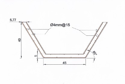
the graduate studies laboratory in the civil engineering department at the Kufa University, Najaf, Iraq. The channels were casted for this experimental work program. The dimensions of all specimens are identical; the channel section is trapezoidal in cross section. So, it is 45cm bottom wide, 60˚ side slope having depth of 40 cm and the length is 160 cm depending on the best hydraulic section for trapezoidal channel. Reinforcing steel for each specimen of channels is in the form of two layers, each layer consisting of longitudinal and transverse reinforcement with diameter 4 mm @15cm spacing shown in figure(1).
The materials used in this study were conformed to Iraq specification. In the present study, the maximum aggregate size was 10 mm. Mix design details are as given in Table (1).
IJSER
Fig. 1 channel dimensions and location of reinforcing steel
Table. 1 Concrete mix design proportions for channels
Ingredients | Quantity |
Total cement (kg/𝑚3) | 420 |
Fine aggregate (kg/𝑚3) | 710 |
Coarse aggregate (kg/𝑚3) | 1100 |
Water (kg/𝑚3) | 159.6 |
Admixture (l/𝑚3) | 3 |
Water/cement ratio | 0.38 |
The experimental study consists of casting four reinforced concrete (RC) channels. The strengthening of the channels is done with vary location of CFRP sheets.
Before conduct flexural examination on strengthened channels from inside , linked channels to be flume with (6.4m) length, after providing all that is necessary for this experiment
until finding Chezy coefficient for two cases: (1) Flume Without
CFRP sheets, and (2) Flume with CFRP sheets.
3 HYDRAULIC MODELING EXPERIMENT
3.1 EXPERIMENTAL FACILITIES:
A. Experimental site. Experiments are conducted at the Hydraulic Engineering Laboratory of Department of Civil Engineering at kufa University (Iraq) using a tilting trapezoidal flume , with a slope (1/320).
B. Reservoir tanks: Source water from two reservoirs Capacity (2000L) with connection pipes by diameter (3 inch). In addition, an outflow tank, 2 m long, 0.8 m wide and 0.5 m deep.
IJSER © 2013 http://www.ijser.org
International Journal of Scientific & Engineering Research, Volume 4, Issue 12, December-2013 933
ISSN 2229-5518
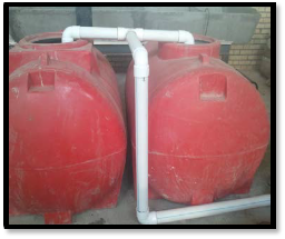
Photo 1 the tanks inflow
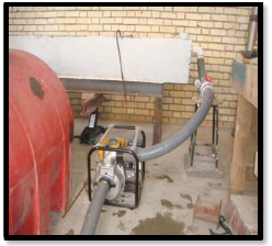
C. Pumps: Water is pumped into the flume from pump with maximum capacity is (12L/sec). In addition, the reflux water pull by another pump, it is same quality as the first pump. The pumping system is supplied with a valve to control the discharge.
from the vertical to produce an edge no thicker than (2mm) and thickness of plate (1cm). In addition, it used from plywood material. It is an accurate flow measuring device particularly suited for small flows and use in calibration between discharge from weir and discharge from volumetric method. The cone equation is commonly used for 90degree V-notch weirs. This equation is reliable for small, fully contracted weirs generally encountered in measuring water for irrigation [16], [17] and [18] .
Q= 1.34H2.48 (1)
Q= discharge over weir in m3/s
H= head on the weir in m.
IJSEPhotoR4 V-notch weir in experimental work
f. Slope Adjusting Automatic Device: two devices used in
experimental work to adjust the bed slope. One of those put in the beginning and the other in mid the flume. After that, we realize the desired slope by bed level device.
Photo 2 pump inflow
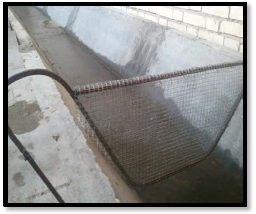
D. Screen: a vertical steel screen at about the middle of the inlet basin For the purpose of calming the flow.
Photo 3 the screen
E. V-notch weir: the weir was used in experimental work is partially contracted standard 90-degree V-notch weir. The crest of the weir consists of a thin plate beveled 45 degrees
Photo 5 Slope Adjusting Automatic Device
G. Steel base for carry the flume.
3.2 EXPERIMENTAL PROCEDURE
IJSER © 2013 http://www.ijser.org
International Journal of Scientific & Engineering Research, Volume 4, Issue 12, December-2013 934
ISSN 2229-5518
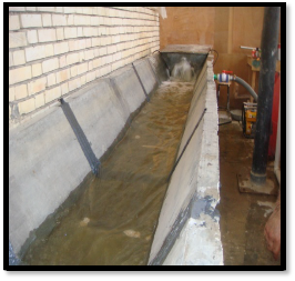
Water is supplied to the experimental setup by a recirculation system of water supply. Pump capacity (3 inch) is used to pump water from processing tanks to the flume by pipes capacity (3 inch). Water is led to a stilling screen located at the upstream of the channel. A series of baffle Walls between the stilling screen and the flume are kept to reduce turbulence of the incoming water. At the end of the experimental channel, water is allowed to flow through a V-notch weir and is collected outflow tank from where it is allowed to flow back to the processing tanks. Water is pumped back, Thus setting a complete re- circulating system of water supply for the experimental channel. The weir is located at (70cm) from downstream, and it helps to measured the discharge and work calibration. The discharges are determined by volumetric method, and then depend on specific five discharges. Experiment is performed on three cases:
1. Concrete channel
2. Concrete channel strengthened by five tapes from (CFRP)
sheets with width (5cm) and long (122cm) with transverse
direction.
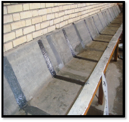
3. Concrete channel strengthened by fifteen tapes from (CFRP) sheets with width (5cm) and long (122cm) with transverse direction.
Each case conducted in the experiment on five discharge (6.5, 8, 9.5, 11 and 12) l/sec. it is calculated from each experiment depth of water, then enter in chezy equation to find chezy roughness coefficient.
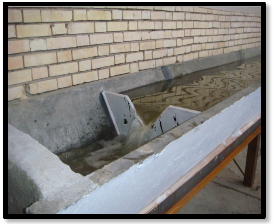
Photo 7 flume with 15 tapes from CFRP sheets
4 STRUCTURAL EXPERIMENTS
In order to investigate the capability of CFRP to strengthen of concrete channels; four specimens made of concrete were prepared. For the concrete channels, one remained without strengthening and was kept as a control specimen (c1),
Q = 𝐶 × 𝑅1/2 × 𝑆ₒ1/2 × 𝐴
IJ(2)
while the rest were strengthening. Table (2) shows the nomenclature and location of strengthening of each group.
Table 2 Nomination of specimens showing the strengthening condition
Photo 6 flume with 5 tapes from CFRP sheets
The channels were simply supported at each end. In order to simulate the real boundary condition of the actual structure. Namely, both horizontal and vertical forces from effect the water. Consequently, the most commonly used load arrangement for testing of channels will consist two patch loading arrangement was done affect on the center the wings of the channel. For all cases the dial gauge was placed just below the center of the channel to measure deflections.
IJSER © 2013 http://www.ijser.org
International Journal of Scientific & Engineering Research, Volume 4, Issue 12, December-2013 935
ISSN 2229-5518
4.1 TEST METHOD
Flexure test was conducted to compare the behavior of the channels with and without CFRP strengthening. Before testing the channel must checked dimension and location the support and dial gauge and a detailed visual inspection made with all information carefully recorded. After setting and reading the gauge, the load was increased incrementally. The loads and deflections recorded at each stage. Loads will then normally be increased again in similar increments up to failure. Similarly, cracking and deflections observations must be suspended as failure approaches unless special safety precautions are taken. If it is essential that precise deflection reading are taken up to collapse. Cracking was checked visually and a load/deflection plot was prepared.
5 RESULTS AND DISCUSSION
5.1 ROUGHNESS COEFFICIENTS IN OPEN CHANNEL
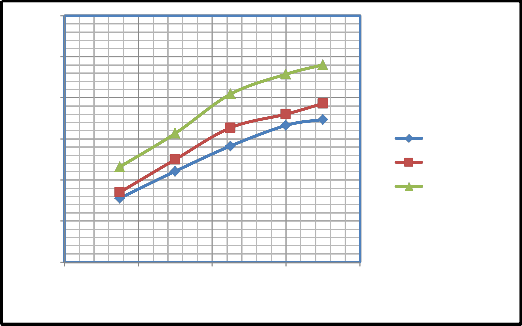
The experimental results for Chezy roughness coefficient (C) with discharge for flume investigated are plotted in figure (3) for slope (0.003125). Chezy coefficient is found to increase with increase of discharge due to higher depth of flow. So, Chezy coefficient is found with put CFRP sheets by five stripes for the purpose of strengthening the flume, its increase for the same discharge for the first case (without CFRP sheets). In addition, more Chezy coefficient is with put (15) stripes from CFRP sheets. The reason for this probably to smooth surface for CFRP sheets which is considered one of the advantages of CFP sheets. So CFRP also beneficial in economic terms because it gives increased in discharge.
Table 3 first case concrete channel without CFRP sheets
IJTable 4 secondScase concrete channEel with 5 stripes of CRFRP sheets
Table 5 third case concrete channel with 15 stripes of CFRP sheets
S (m/m) | Q (𝒎𝟑/𝒔) | 𝒚𝒖𝒑 (cm) | 𝒚𝒅𝒐𝒘𝒏 (cm) | 𝒚𝒂𝒗𝒈 (cm) | A (𝒎𝟐) | P (m) | R (m) | C |
0.003125 | 0.0065 | 4.5 | 3 | 3.75 | 0.015523 | 0.4788875 | 0.032414 | 41.6 |
0.003125 | 0.008 | 4.9 | 3.2 | 4.05 | 0.016835 | 0.4858145 | 0.034652 | 45.68 |
0.003125 | 0.0095 | 5.2 | 3.3 | 4.25 | 0.017715 | 0.4904325 | 0.036121 | 50.47 |
0.003125 | 0.011 | 5.6 | 3.5 | 4.55 | 0.019044 | 0.4973595 | 0.038291 | 52.88 |
0.003125 | 0.012 | 5.9 | 3.6 | 4.75 | 0.019936 | 0.5019775 | 0.039715 | 54.03 |
IJSER © 2013 http://www.ijser.org
International Journal of Scientific & Engineering Research, Volume 4, Issue 12, December-2013 936
ISSN 2229-5518
60
55
50
45 C without CFRP C with 5 CFRP
40 C with 15 CFRP
35
30
0.005 0.007 0.009 0.011 0.013
Discharge m3/sec
Fig. 2 Chezy coefficient vs. discharge for slope=0.003125
5.2 FLEXURAL TESTIRESULJT SER
In the current study, in all the channels, the failure
occurs starting with flexure cracks at corners followed by interfacial debonding failure of the CFRP system. The CFRP strengthened channels and the control channel were tested to find out their ultimate load carrying capacity. It was found, Failure in the control channel (C1) was typical that of under- reinforced
RC flexural members, which is characterized by yielding of steel
rebars followed by concrete crushing. In channels (C2), (C3) and (C4) failure was caused by crushing of concrete followed by debonding of the CFRP from the concrete.
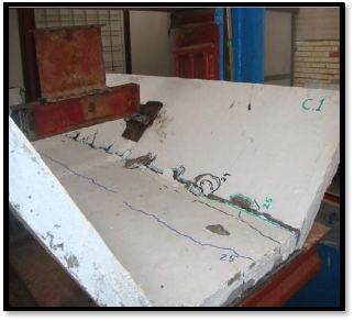
Photo 8 Final Failure in control channel C1
IJSER © 2013 http://www.ijser.org
International Journal of Scientific & Engineering Research, Volume 4, Issue 12, December-2013 937
ISSN 2229-5518

Photo 9 Final Failure in control channel C3
Table 6 summarizes the experimental values for initial crack and ultimate capacity obtained in each test.
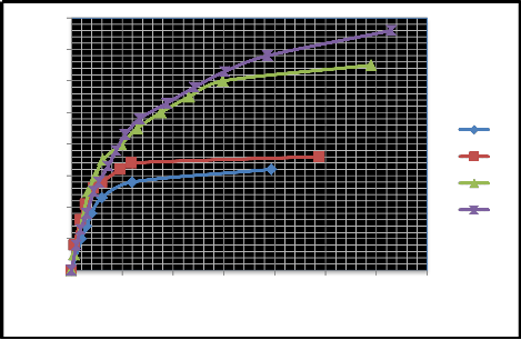
channels C2, C3 and C4. Channel C1 had also undergone higher deflection compared to channels C2, C3 and C4 at the same load. Channel C2 had higher ultimate load carrying capacity
compared to the controlled channel C1 but lower than channels C3 and C4. Channel C3 had higher ultimate load carrying capacity compared to the channels C1and C2 but lower than channels C4. Channel C4 had higher ultimate load carrying capacity compared to the channels C1, C2 and C3. The deflection undergone by channel C4 is highest, channel C3 had undergone higher deflection than channel C2, and channel C2 had undergone higher deflection than channel C1. The figure (7)
From the load and deflection of data of channels C1, C2, C3 and C4, load vs deflection curve is plotted for all the four channels. From this load vs deflection curve, it is clear that channel C1 lower ultimate load carrying capacity compared to
showed load vs deflection curve for channels C1, C2, C3 and C4 for dial gauge at mid-span.
IJSER © 2013 http://www.ijser.org
International Journal of Scientific & Engineering Research, Volume 4, Issue 12, December-2013 938
ISSN 2229-5518
40
35
30
25
c1
20
c2
15 c3
10 c4
5
0
0 0.5 1 1.5 2 2.5 3 3.5
Deflection in mm
Fig. 3 load vs deflection curve for channels C1, C2, C3 and C4
6 CONCLUSIONS
[4] Gustavo Tumialan, Paolo Serra, Antonio Nanni and Abdeldjelil Belarbi, (1999). “Concrete cover delamination in RC beams strengthened with FRP sheets” P-188, American Concrete Institute, pp. 725-735.
The experimental set-up was designed to evaluate strengthening of concrete channel by externally bonded CFRP reinforcement. In addition, this study presents the effect of CFRP sheets on the Chezy roughness coefficient in an open channel. Consequently, two tests have conducted with four specimens of channel. The hydraulic test results indicate that Chezy coefficient (c) is increase with increasing ratio of CFRP sheets to concrete. Namely, At the slope (0.003125), the Chezy coefficient is about (4%) increases in the maximum discharge when the CFRP sheets is 5 stripes in channel and about (12.3%) increases when the CFRP sheets are 15 stripes in channel. In addition, the flexural test indicate that The externally bonded CFRP sheets have increased the stiffness and maximum load of the channels and The cracks and the deflections have decreased for strengthened channels. We suggest that further research could focus on the vegetated effects of CFRP sheets and usage of the extended finite element method to represent the cracks in the concrete.
REFERENCES
[1] Bartos P., (1991). “Performance parameters of fiber reinforced cement based composites”. Proceedings of the International RILEMAC/ACI Workshop, pp 431-44.
[2] Nanni, A., (1995). “Concrete repair with externally bonded FRP reinforcement,” Concrete International, Vol. 17 No.6, pp.22-26.
[3] Catalin Andrei Neagoe, (2011). “Concrete beams reinforced with CFRP laminates” university of Catalonia, Barcelona.
[5] Nabil Mohamed, (2011). “Computational study on shear strengthening of RC continuous beams using CFRP sheet’’ Faculty of Civil and Environmental Engineering, University Tun Hussein Onn Malaysia (UTHM).
[6] Takahashi, Y., Sato, Y., Ueda, T., Maeda, T. and Kobayashi, A., (1997). ‘‘Flexural behavior of RC beams with externally bonded carbon fiber sheet” Proc., 3rd Int. Symp., Non- Metallic (FRP) Reinforcement for Concrete Struct., Vol. 1, Japan Concrete Institute, Tokyo, 327–334.
[7] Nishikant dash, (2009). “Strengthening of reinforced beams using GFRP composite’’ master of technology in structural engineering, Rourkela, India.
[8] Adel El-Safty, (2008). “Extending the Service Life of Bridges Using CFRP Laminates and Continuous Decks” University of North Florida, Journal of Structural Engineering, ASCE
[9] Chakrapan Tukakta, (2005). “Use of fiber reinforced polymer composite in bridge structures” civil and environmental department, Massachusetts institute of technology, USA.
[10] S. Schiebel, R. Parretti, A. Nanni and M. Huck, (2000). “Strengthening and load testing of three bridges in Boone county” Center for Infrastructure Engineering Studies, University of Missouri – Rolla.
[11] Sreenivas Alampalli, (2006). “Effectiveness of FRP Wrap for Temporary Repairs in R/C Bridge Column Applications” Journal of Structural Engineering, ASCE.
[12] S.H. Petro, J.T. Peaslee and T.G. Leech, (2010). “Strengthening a concrete slab bridge using CFRP composites” Structural Engineering, USA.
[13] Pinaki Prasanna Nayak, (2010). “Meandering effect for evaluation of roughness coefficients and boundary shear distribution in open channel flow” Master thesis of technology in civil engineering, Rourkela.
[14] John E. Gilley, Eugene R. Kottwitz and Gary A. Wieman, (1991). “Roughness Coefficients for Selected Residue
IJSER © 2013 http://www.ijser.org
International Journal of Scientific & Engineering Research, Volume 4, Issue 12, December-2013 939
ISSN 2229-5518
Materials” Biological Systems Engineering, University of
Nebraska – Lincoln.
[15] Zarina Md Ali and Nor Ashikin Saib, (2011). “Influence of bed roughness in open channel’’ Department of Water and Environmental Engineering, University Tun Hussein on Malaysia.
[16] USBR TEST, (2001). “Water measurement manual” U.S.
Government Printing Office, Washington, DC 20402.
[17] Ernest F. Brater, Horace Williams King, James E. Lindell, C.Y.Wei, (1996). “Hand book of Hydraulics. Seventh edition”, McGraw-Hill Book Company N.Y, ISBN 0-
07007247-7.
[18] Chow, V.T., (1959). “Open channel hydraulics”: New York, McGraw-Hill, p. (98-115).
IJSER
IJSER © 2013 http://www.ijser.org