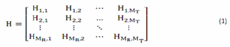
The MIMO signal model is described as
Whereas r is the received vector, s is the transmitted vector, n is the noise vector and H is the channel matrix.
International Journal of Scientific & Engineering Research, Volume 6, Issue 2, February -2015
ISSN 2229-5518
Enhancement of Traffic Capacity at High Data
Rate using MIMO Technology
Swati Kumari, Rabindranath Bera, Sourav Dhar
733
Index Terms— Multiple input multiple outputs (MIMO), orthogonal frequency division multiplexing (OFDM), Bit Error Rate (BER), Quadrature
Amplitude Modulation (QAM), Intersymbol interference (ISI).
—————————— ——————————
The requirement of mobile communications, wireless internet access for high data rate is growing exponentially and there is a strong demand for advanced wireless technique. The goal of wireless communication are narrower bandwidth, high throughput, error free transmission and low power consump- tion. The demand is not only for voice and data services but also for the multimedia services [1], [2].As the user demand are increasing Multiple antennas used at both transmitter and receiver are widely used to form multiple input multiple out- put (MIMO) system used in wireless communication offers various benefits such as better transmission quality (low bit error rate) and higher capacity [3].
Channel in the wireless communication is mainly affected by
multipath fading. In wireless telecommunication, multipath is the propagation phenomenon which results in the arrival of transmitted signal at receiver with two or more path and with different time delays and frequency. To mitigate this problem MIMO diversity schemes were developed [4], [2]. If the delay caused by multipath is large enough there will be bit errors in the packets and receiver won’t be able to distinguish between symbols. By using traditional MIMO and OFDM technique it
is difficult to meet the above requirement however the hybrid MIMO-OFDM can meet these requirements [5]. OFDM is a frequency division multiplexing scheme used as a digital mul- ticarrier modulation method in which large number of closely spaced orthogonal subcarrier signals are used to carry data on several parallel streams or channel.
MIMO system takes the advantage of multiple signals to im- prove the quality and reliability of transmitted information signal and it also increases the capacity of the system while OFDM minimizes the intersymbol interferences (ISI) and
————————————————
Ms. Swati Kumari is currently pursuing master degree in electronics and Communication engineering in Sikkim Manipal Institute of Technology, India, E-mail: swatisingh.taurus@gmail.com
Prof. (Dr.) RabindranathBera is a professor & HOD of electronics and Communication engineering in Sikkim Manipal Institute of Technology, India, E-mail: rbera50@mail.com
Dr. Saurav Dhar is a Associate Professor of electronics and communication engineering in Sikkim Manipal Institute of Technology, India, E-mail: sou- rav.dhar80@gmail.com
utilizes the spectrum very efficiently.
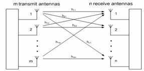
MIMO system consists of Mt transmit antennas and Mr re- ceiver antennas as shown in fig.1 [8], the MIMO channel may be represented as a Mr x Mt matrix
The MIMO signal model is described as![]()
Whereas r is the received vector, s is the transmitted vector, n is the noise vector and H is the channel matrix.
Fig 1: Multiple Input Multiple Output System Block Diagram
Capacity of the MIMO system increases linearly while there is a logarithmic increase for SISO, SIMO and MISO system.
Capacity for the SISO system is given as![]()
Where C is the Capacity of the system, B is the bandwidth and
IJSER © 2015
International Journal of Scientific & Engineering Research Volume 6, Issue 2, February -2015
ISSN 2229-5518
734
S/N denotes signal to noise ratio.
Capacity for the MIMO system is given as![]()
Where M= min (Mt, Mr) is the smaller of Mt and Mr, B is the signal bandwidth and S/N is the signal to noise ratio [4, 5, 6].
Orthogonal frequency division multiplexing is a special case of multicarrier transmission where data bits are encoded to multiple subcarriers, while being sent simultaneously. OFDM is a combination of modulation and multiplexing technique. In OFDM multicarrier are used so under fading condition, only small percentage of subcarrier are affected while in case of single carrier if signal get fade then entire link gets failed.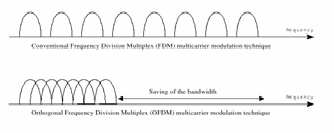
Fig 1: Comparison between FDM and OFDM
As seen from the fig 2, FDM uses guard band between differ- ent carriers which makes inefficient use of spectrum while in OFDM orthogonality between subcarrier is maintained to avoid ISI and makes efficient use of spectrum [5, 7].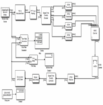
Transmit and 1 Receive Antenna
In the present study block OFDM with MIMO is designed. As seen in the figure block diagram represents the whole system model. Here we have discussed only for four transmitter and one receiver antenna. The block diagram consists of 3 main sections namely OFDM transmitter, MIMO channel and OFDM receiver. MATLAB Simulink is selected due to its real time environment which resembles its real time design. Para- meters used in this model are given in the following table-
TABLE 1
Parameters used for 16 QAM MIMO and OFDM MIMO
The data is generated using the random data source (Bernoulli Binary). The transmission is completed block wise. Generated data is passed to the next block that is FEC block. Reed and Solomon encoder is used where the data is encoded and the padding of bits is done here whose constraint length is 7 and code rate is 1/2. 16 QAM modulation scheme is used which maps the bits to symbol. For 16 QAM 4 bits/symbol is trans- ferred. These symbols are passed to the space time encoder block which converts one single input data streams into mul- tiple output data streams. To reduce the noise interference different symbols are simultaneously transmitted over these antennas.
Fig 1 (a): Experimental System Model-MIMO-OFDM with 4
IJSER © 2015
International Journal of Scientific & Engineering Research Volume 6, Issue 2, February -2015
ISSN 2229-5518
735
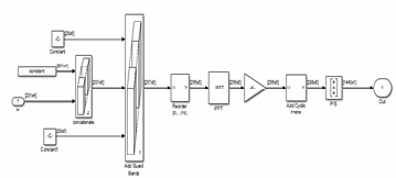
Fig 1(b): OFDM Transmitter
The transmitter block consists of selector, IFFT, cyclic prefix, parallel to serial convertor and gain is added. Selector block is used to reorder the subcarriers. IFFT is used to convert the signal to time domain and also it maintains the orthogonality between subcarriers. IFFT reduces the computational com- plexity. On the time domain signals only cyclic prefix is add- ed. Cyclic prefix is the copy of the last portion of the data symbol appended to the front of the symbol. And then parallel data is converted to serial and it is transmitted over multipath MIMO channel. Guard band are introduced to each symbol for the removal of ISI.
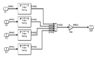
Fig 1(c): MIMO Channel
Based on fading distribution, variety of fading model is there and in this we have used rician fading model. Rician fading is a stochastic model for radio propagation caused by partial cancellation of a radio signal by itself-the signal arrives at the receiver by different paths (exhibiting multipath interference), and at least one of the path is changing. Rician fading occurs when at least line of sight signal, is much stronger than the others. After this the signal is passed through AWGN channel.
Receiver block consists of removal of cyclic prefix, serial to
parallel convertor, FFT and again parallel to serial converter. First task done here is a removal of cyclic prefix which re- moves inter-symbol interference. The data is then passed through serial to parallel convertor after which FFT is used for frequency domain transformation. As signal is passed through channel it might be distorted so to overcome this and to obtain the original transmitted signal demodulation and equalization is used.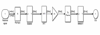
Fig 1(d): OFDM Receiver
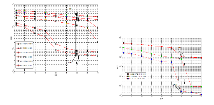
The simulation model has been implemented in MATLAB R2013a Simulink. In this section SISO (1x1), SIMO (1x2), MISO (2x1, 3x1, 4x1) and MIMO (2x2, 3x3, 4x4) systems BER along with capacity results are presented. By using Monte Carlo si- mulation BER graph is obtained. BER is the ratio of the num- ber of errors in the bits to the total number of bits transferred.
Fig 1: Comparison between SISO, SIMO, MISO, MIMO
In the above figure it is clearly seen that there is a drastically decrease in BER for MIMO system. For higher SNR decrease in BER is high. Variation in BER is very less for SISO (1x1) and SIMO (1x2). By an ellipse it is shown that there is a high de- crease in BER when we are using MIMO system.
IJSER © 2015
International Journal of Scientific & Engineering Research Volume 6, Issue 2, February -2015
ISSN 2229-5518
736
4x4) using 16QAM and 16QAM+OFDM. OFDM performance is better than 16QAM. As seen from the graph the values of BER for 2x2 OFDM and 3x3 16QAM are approximately same for low SNR values and for high SNR 2x2 OFDM performs better than 3x3 16QAM and BER performance is evaluated for remaining 3x3 16QAM+OFDM+MIMO, 4x4 16QAM+MIMO and 4x4 16QAM+OFDM+MIMO.
Fig 2: Comparison for MISO (2x1, 3x1 4x1) system using 16QAM
and OFDM
Above figure shows performance of system when we are us- ing 16QAM as a modulation and 16QAM with OFDM as a modulation, code rate is ½ and number of FFT points 512, channel is Rician Fading for MISO system (2x1,3x1,4x1). Per- formance of all these three system has been simulated and observed. It is observed that for the same system like 2x1 when 16QAM is used BER is 0.34 is higher than 2x1 with
16QAM+OFDM is used i.e. BER for this is 0.256 at SNR 30 db.
For the same SNR at 30 dB when 3x1 is used with 16QAM BER
is 0.214 and for 3x1 with OFDM+16QAM BER is 0.087. It is
clear from above that with use of 16QAM+OFDM+ MIMO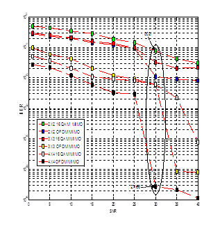
system results are better than normal 16QAM+MIMO system.
Fig 3: Comparison for MIMO (2x2, 3x3, 4x4) systems using
16QAM and OFDM
Above graph is for comparison of MIMO system (2x2, 3x3,
Fig 4: Comparison between 2x2, 3x3, 4x4 OFDM MIMO
Fig (4) shows the comparison between MIMO systems i.e. 2x2,
3x3, 4x4 OFDM+ 16QAM +MIMO system in the rician fading
channel, code rate is ½ and FFT points used is 512. Results shows that with more antennas and with use of OFDM with it
there is a drastically decrease in BER. Hence 4x4 OFDM shows the better performance.
Data rate can be measured by varying sampling frequency (Fs)
and sampling time period (Ts). Here sampling time Ts=8.333e-
6 then sampling frequency will be Fs=1/8.333e-6 = 0.1 MHz i.e., 0.1 Mbps. To obtain the high data rate Ts is set to 4.762e-8,
Fs= 1/Ts = 21MHz so data rate for single stream becomes 21
Mbps and then data rate of four streams (4x4 MIMO) becomes
84 Mbps. When Ts= 3.762e-8 then Fs becomes 26 MHz which
is data rate for single stream and then data rate of four streams
(4x4 MIMO) becomes 104 Mbps. By increasing the number of antennas the data rate is also increased.
We have designed a model for SISO (1X1), SIMO (1X2), MISO (2X1, 3X1, 4X1) and MIMO (2x2, 3x3, 4x4) system using MAT- LAB Simulink. BER is obtained using Monte Carlo simulation. Capacity for the MIMO system is higher than the SISO, SIMO and MISO system which shows that MIMO technology will have maximum data rate. There is a possibility of achieving high data rate by increasing the number of antennas and also by varying the sampling time and this high data is the re- quirement of future generation wireless communication. OFDM MIMO gives better performance than MIMO used with normal modulation (i.e. 16QAM is used here). There is a dras- tic decrease in BER performance when the system is used with
IJSER © 2015
International Journal of Scientific & Engineering Research Volume 6, Issue 2, February -2015
ISSN 2229-5518
737
OFDM MIMO which shows probability of error is very less. This hybridization technology has been proposed for future generation wireless technologies and has a significant growth in existing applications to enhance the capacity, data rate and decreases the bit error rate. For better enhancement of data rate and for decrease in bit error rate Generalized Frequency Division Multiplexing can be used for future wireless technol- ogy which uses special pulse shaping filter.
[1] Shubhangi Chaudhary and A.J. Patil, ―Performance Analysis of MIMO Space Time Block Coding With Different Modulation Techniques’’, IC- TACT Journal on Communication Technology, March 2012, Volume: 03, Issue: 01.
[2] Nirmalendu Bikas Sinha, Makar Chand Snai, M.Mitra, ―Performance Enhancement of MIMO- OFDM for High Data Rate Wireless Network‖, International Journal of Computer Science and Application Issue 2010.
[3] Archana Ogale, Shubhangi Chaudhary and Anil J Patil, ―Performance
Evaluation of Hybrid MIMO-OFDM system using MATLAB SIMULINK with Real Time Image Input‖, International Journal of Scientific & Engi- neering Research, Volume 4, Issue 5, May- 2013.
[4]Rohit Gupta and Amit Grover, ―BER Performance Analysis of MIMO
System using Equalization Techniques‖, Innovative Systems Design and Engineering, ISSN 2222-1727 (Paper) and ISSN 2222-2871 (Online), Vol 3, No 10, 2012.
[5] Vibha Rao and Malavika T, ―MIMO-OFDM Hybrid Technology for
Wireless Communication System‖, International Journal of Advanced Research in Computer Science and Advanced Engineering, Volume 4, Issue 4, April 2014.
[6] Rajeev Singh, ―MIMO System using Space-Time Block Code with Digi-
tal Modulation Techniques‖, International Journal of Electrical and Elec- tronics Research (IJEER), Vol. 1, Issue 1, pp: (26-31), Month: October- December 2013.
[7] Nilesh Chide, Shreyas Deshmukh, Prof. P.B. Borole , ―Implementation
of OFDM System using IFFT and FFT‖, International Journal of Engineer- ing Research and Applications (IJERA), Vol. 3, Issue 1, January-February
2013, pp.2009-2014.
[8] Rajesh S. Bansode & Prajakta Borole, ― Hardware Implementation of an
OFDM Transceiver for 802.11n systems‖, International Journal of Scientific
& Engineering Research, Volume 4, Issue 6, June- 2013, ISSN 2229-5518.
[9] G.J. Foschini and M.J. Gans, ―On Limits of Wireless Communications in a Fading Environment when using Multiple Antennas‖, Wireless Per- sonal Communication, vol. 6, no. 3, pp. 311-335, 1998.
[10] M. Chethan Kumar, Sanket Dessai, ―Design, Implementation and Optimization of 4x4 MIMO-OFDM Transmitter for Communication Sys- tems‖, SASTECH Journal, Volume 12, Issue 2, September 2013.
[11] V. Taroka, N. Seshadri and A.R. Calderbank, ―Space-Time Code for High Data Rate wireless communication: Performance Criterion and Code Construction‖, IEEE Transaction on Information Theory, Vol. 44, No. 2, pp.744-765,1998.
[12] Hadj Zerroukki, Mohamed Fahem, ―High Throughput of WiMAX
MIMO-OFDM including Adaptive Modulation and Coding‖, IJCSIS 2010,
Vol. 7, No1.
[13] I. E. Telatar, ―Capacity of multi antenna Gaussian channels‖, Eur.
Trans. Commun., vol. 10, no. 6, pp. 585-595, 1999.
[14] H. Sampath, S. Talwar, J. Tellado, V. Erceg, and A. Paulraj, ―A fourth- generation MIMO-OFDM broadband wireless system: design, perform- ance, and field trial results,‖ IEEE Communications Magazine, vol. 40, no.
9, pp. 143–149, 2002.
[15] T. E. V. Vamsee Krishna and G Teja Ravishankar, ―Enhancing MIMO
features for OFDM,‖ in IEEE 978-1-4244 6589-7/10, ICCCN 2010.
[16] Yu Wei Lin and Chen Yi Lin, ―Design of FFT/IFFT Processor for MI-
MO OFDM Systems‖, IEEE Transaction on circuit and system, vol. 54, no.
4, pp. 807-815, 2007.
[17] S. Dhar, A. Ray and R.Bera (2012), ―Cognitive Vertical Handover Engine for Vehicular Communication‖, Peer to Peer Netw. And Appl., Springer, New York. 2012.; doi: 10.1007/s12083-012-0171-5
IJSER © 2015