Inte rnatio nal Jo urnal o f Sc ie ntific & Eng inee ring Re se arc h, Vo lume 3, Issue 3, Marc h-2012 1
ISS N 2229-5518
Electronic Line Shafting-Control for Paper
Machine Drives
AvinashWankhede, J. P. Modak, K.S. Zakiuddin, G. D. Mehta, M.K Sonpimple
Abs tract - This paper deals w ith the perf ormance analysis of the paper manuf acturing process through synchronized motion control system. The current synchronized motion control method used in paper machine drives are not designed to posses the inter -shaf t stiff ness properties w hich w ere responsible f or the coordinating f orce inherent in classical, mechanically coupled paper machines. Consequently, these controllers cannot easily maintain coordination f or all operating condition. This paper presents the application of an “Electronic line- shaf ting” control technique w hich serves to replicate and even improve on the mechanical line-shaf ted properties.
Keyw ords-Electronic line shaf ting, Drive system.
————————————————————
he objective of choosing this work is, in some of the paper industry is still using synchronized motion control me- thod. Currently used synchronized motion control is not sufficient to synchronized speed of the entire rolling cylinder. Due to speed synchronization in paper machine, lots of prob- lem is arrive like paper breaking, paper thickness is not main- tain constant , quality if the paper. To synchronize speed of rolling cylinder electro mechanical control system needs to
use.
In Nagpur region most of the paper industry is use synchron- ize motion control system,one of paper mill from Bazargaon MIDC was identified, which use motion control system. Ba- zargaon paper mill is located in Bazargaon village. 35 Km away from Nagpur, on Nagpur-Amravati road, plant is ha v- ing capacity 100TPD currently Bazargaon paper mill is opera t- ing on mechanical line shaft drive system. The systemconsists of a speed controlled motor driving a long shaft all the way along the different mechanical section. Each section is coupled to the line shaft through a gear box, conical pulleys, and the section connecting shaft. This mechanical arrangement assures that the entire system shaft will remain rigidly locked to each other through the common line shaft, even in the presence of disturbances on individual section. The only steady-state rela- tive motion is due to torsional windup of shafts transmitting the driving torque.
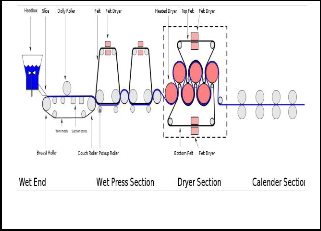
Fig.1 shows the schematic diagram of paper making process, the papermaking process is to dilute and disperse the pre- pared material, or paper stock, spray the paper stock on wire cloth to form a paper sheet, and drain water from the sheet and dry it. A paper machine consists of a paper machine main- frame and auxiliary equipment. The paper machine main- frame consists of a stock inlet, wire part; press part, dryer part, size press, calender, and reel along the flow of materials. The auxiliary equipment consis ts of a driving unit, approach pipes that supply raw materials and circulate white water, a vacuum system that drains water from the wire part and press part, a
drainage system that supplies and recycles steam for the dryer bank, an air system that circula tes and uses air for drying and recovers waste heat, etc. Papermaking machines are roughly classified into the Fourdrinier machine and the cylinder ma- chine according to the type of wire part, and the multiple c y- linders dryer and the Yankee dryer according to the type of dryer part. [1]
Early paper machine drives were constructed with mechanical interconnection components that produced motion with re- spect to a common line-shaft input. The mechanical power was produced by a single motor driving a line shaft to which all of the in-shafts were attached.
Fig.2 shows a simplified arrangement of a line-shaft drive. It
consists of a speed-controlled motor driving a long shaft all the way along the different mechanical sections. Each section is coupled to the line shaft through a gear box, conical pulleys, and the section connecting shaft. Conical pulleys allow draws to be set in the different mechanical sections. Assuming no belt slip in the conical pulleys, this mechanical arrangement assures that all the system shafts will remain rigidly locked to each other through the common line shaft, even in the pres- ence of disturbances on individual sections. The only steady- state relative motion is due to torsional windup of shafts transmitting the driving torque. [2]
IJSER © 201 2
Inte rnatio nal Jo urnal o f Sc ie ntific & Eng inee ring Re se arc h, Vo lume 3, Issue 3, Marc h-2012 2
ISS N 2229-5518
of synchronization might cause a web break.
Therefore, although the increased power and flexibility a l- lowed by sectional drives provided enormous strides in paper manufacturing, it lost the inter-shaft state feedback inherent to the line-shafted drives which was the driving force for the coordination of the multiple mechanical sections. Its properties are not achieved by the sectional drive control topology cur-
rently in use [2]
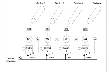
Fig. 1– SCHEMATIC D IAGRAM OF F OURDRINIER MACHINE SECTIONS
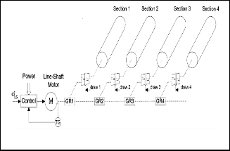
Fig. 3 – SECTIONAL DRIVE SYSTEM
Fig. 2 – LIN E SHAFT DRIVE SYSTEM
As advances in power electronics and high -performance drives became available, the line-shaft structure evolved into modern, individual dc and ac sectional drives, which allow an increase in the operating speed and sectional power of paper machines. Fig.3 shows a simplified arrangement of a sectional drive. Each mechanical section is driven by a fully controlled drive (some sections might have more than one). All the sec- tional drives are ―electronically synchronized‖ through the master reference command and the draws are set adding an auxiliary signal to the master reference. During a load distu r- bance in such a system, the speed in the disturbed section will decrease momentarily until the drive control is able to restore it to the reference speed. During this transient period, the loss
AvinashWankhede is currently pursuing masters degree program in Mechani- cal Engineering Design in Nagpur University,India,
E-mail: avinash_wankhede21@rediffmail.com
DrJ.P.ModakisDean(R&D) &Professor InPriyadarshini College of Engineer-
ing, Nagpur, India.
Dr .K.S.Zakiuddin is Dean Academics,Professor& Head of department in
Priyadarshini College of Engineering,Nagpur,India,
E-mail: qszaki1@rediffmail.com
DrG.D.Mehta is Asso Professor in Priyadarshini College of Engining , Nagpur,
India, E-mail: gdmehta@gmail.com.
Prof.S.K.Sonpimpale is Asso Professor in P.C.E, Nagpur. India
Fig. 4 shows the block diagram of the proposed control stru c- ture. This control structure replicates the mechanical line shaft machine of Fig. 3. It contains ―a virtual line-shaft drive,‖ ―vir- tual in-shafts,‖ and ―virtual gear-box conical pulleys‖ combi- nations to replicate ideal physical elements. In order to obtain the simplest model, the line shaft has been assumed perfectly stiff, and only the in-shafts’ stiffness and damping attributes are considered.
The physical line-shaft drive can be described as a virtual mas-
ter reference that sets the instantaneous position![]() and velocity (
and velocity (![]() ) references to the sectional drives. Since the virtual line-shaft drive (master reference) is not physical, the values of
) references to the sectional drives. Since the virtual line-shaft drive (master reference) is not physical, the values of ![]() and
and ![]() are relatively unconstrained control variables that are set to accomplish the desired dynamic per- formance with feasible trajectories to the follower drives.
are relatively unconstrained control variables that are set to accomplish the desired dynamic per- formance with feasible trajectories to the follower drives.
The virtual compliant connecting in -shafts establish the basic relative state feedback needed to force the master reference to slow down or to speed up according to the load changes in the mechanical sections. Thus, these virtual in -shafts provide the coordination needed for relative motion control during load disturbances. A critical difference between the mechanical line-shafted system and the proposed electronic line-shafting
IJSER © 201 2
Inte rnatio nal Jo urnal o f Sc ie ntific & Eng inee ring Re se arc h, Vo lume 3, Issue 3, Marc h-2012 3
ISS N 2229-5518
control for sectional drives arises from different physical li m- its. The synchronization limit of the mechanical line-shafted system is the torque capacity of the line shaft and in -shafts (or slip of the conical pulleys). The torque capacity of the mechan- ical shafts was generally far in excess of the torque needed for even worst case loading scenarios. By comparison, the distri- buted sectional drives are limited by torque and/or velocity limits of the drives. Peak torque limits of modern drives are generally only a factor of 2 above the rated torque. This rather low limit makes sustained operation in torque limits a very important issue.
If a sectional drive hits a torque limit and begins to fall behind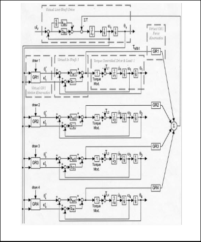
the line-shaft reference, the electronic line-shafted system au- tomatically increases the torque reflected back to the virtual line shaft. This torque feedback causes the line shaft to decel e- rate, which, in turn, causes all drives to decelera te to keep syn- chronized to the limited drive. [1]
Fig.4 – LIN E-SHAFT DRIVE SYSTEM
Electronic line-shafting control has been developed to emulate the inter-shaft stiffness inherent to cla s- sical line-shaft drives.
It is inherently capable of maintaining synchroniz a-
tion between the axes during startup and shutdown and even during extreme or abnormal load condi- tions.
Its mechanical counterparts, electronic line-shaft
control allows the designer to effectively apply well- damped ―electronic‖ shafts which do not cause re- sonance problems in the system and inherently pro- vide well-damped section-to-section dynamics.
This feature provides a very attractive secondary
benefit. It is quite well known in machine controls that ―soft,‖ i.e., low-bandwidth, servo control tends to provide smoother machine operation than ―hard,‖ i.e., high-bandwidth servo control.
By providing well-behaved section-to-section dy-
namics, electronic line-shafting diminishes the need for individual drive hard servo control.
In paper machine drives, this control topology a l-
lows the drive system to handle torque and speed limits in any sectional drive, and load disturbances in any section.
In addition to the well-behaved disturbance-
handling properties that can be achieved, electronic line-shafting control also demonstrates fast response to loads due to its inherently direct ―torque- controlled‖ operation.
The results demonstrate that this control can effec- tively handle sectional drive current (torque) limits and load disturbances in any sectional drive, mai n- taining synchronized motion between the different mechanical sections.
Use of electronic line-shafting control in paper ma-
chine drives could provide significant strides to the machine capabilities, comparable to those obtained when the sectional drive replaced the mechanical line-shaft system.
This approach will make the machine less sensitive
to mismatched controller tuning since the electronic relative stiffness and damping will dominate the dynamics. Electronic line shafting will make the ma- chine less sensitive. To improper ramp rate settings or draw signals. Startup and shutdown synchroniz a- tion can, thus, be maintained. As a consequence, web breaks could be greatly reduced while allowing
full utilization of the machine drive capabilities.
IJSER © 201 2
Inte rnatio nal Jo urnal o f Sc ie ntific & Eng inee ring Re se arc h, Vo lume 3, Issue 3, Marc h-2012 4
ISS N 2229-5518
1. PRTR estimation manual, Ja pan Paper association, Jan 2001 re- vised Mar 2002
2. M Anibal Valenzuela and Robert D Lorenz , “EletroLine shafting
control for paper machine drives” in Conf Rec. IEEE-IAS Annual meeting, 2001
3. R. D. Lorenz and P. B. Schmidt , “Synchronized motion for process automation” in Conf Rec. IEEE-IAS Annual meet- ing, 1989, pp-1693- 1699.
4. R. G. Anderson, A. J. Meyer. A. Valenzuela, and R. D. Lo- renz,“Web machine coordinated motion control via electronic line-Shafting,”in Conf. Rec. IEEE-IAS Annual Meeting,
1999, pp. 300–306.
5. A. J. Meyers, “Design and implementation of a multiprocon- trol system for a multi-axis, cross coupled machine con- trol,”M.S. thesis, Dept. Elect. Computer Eng., Univ. Wisconsin,
Madison, Dec. 1994.
6.R. D. Lorenz and K. Van Patten, “High resolution velocity estima-
tion for all digital, AC servo drives,” IEEE Trans. Ind. Appli-
cation., vol. 27, pp 701–705, July/Aug. 1991 .
IJSER © 201 2