International Journal of Scientific & Engineering Research, Volume 3, Issue 10, October-2012 1
ISSN 2229-5518
Ejection Seat Mechanism in Civil Aircraft
Richard Johnson
Abstract—this paper deals with the ejection system that can be implemented in a civil aircraft. It is important for an aircraft to have an ejection seat in case the plane meets an accident in a battle or during test flight and the pilot has to bail out to save his or her life. The mechanism involves lifting of the pilot to a safe distance away from the aircraft and then deploying the parachute. As there is increas e in air traffic, this ejection system provides additional safety measures to the life of passengers. By this method along with the pilot, the crew members and the passengers can be saved. This ejection system consists of a specially made ejector pad, track system and parachute. The ejection system is governed by a timing sensor which ensures that the movement of the passenger seat take place in equal interval of time to avoid collision between two consecutive seats.
Index Terms- Bail, ejector pad, track system, ejection, hydraulic, propulsion, stability.
—————————— ——————————
empty weight. Instead of high propulsive power, simple
1 INTRODUCTION
1.1 Problem statement
Ejection seats have been traditionally fitted in military aircraft from the late 1940’s and onwards. But it was not used in the civil aircrafts because of the following reasons.
1.) Military pilots wore suitable suit which can be an
advantage life saver if the ejection has to effect at high altitudes, but was very difficult and delay in dressing up and checking operation of wear with passengers.
2.) For the effective ejection of all the passengers in a
large civilian aircraft it would have to be built to
disintegrate into predefined parts permitting everyone inside a fair chance of getting safety. The defect in a way as once the fuselage is broken up in traditionally or in an accident the occupants have very poor chance of survival.
3.) The ejection seats weigh very high and when occupants ejected and deploying with multiple parachutes causes collision. And it increase weight which is not suitable to fly an aircraft.
4.) For propelling of seats it need high fuel and cost of
such airlines would be simply astronomic.
1.2 Objective
In the fighter aircrafts at the time of ejection the canopy is first opened and the ejection seat is bailed out with the pilot, this system can be also used in the civil airplane to bail out the pilot, but as by the civil aircraft laws, the pilot is responsible for the safety of the passengers.
At the same time the passengers cannot be ejected like in the fighter airplanes because we cannot open the roof of
the airplane and cannot eject large number of passengers at a time.
To do so we need high propulsive power to eject all
the seats. If we do so it may cause collision of the successive seats that ejected and it made serious problem. For this it need Catapult, Rocket, Restraints and Parachute for all the passengers. It will increase the weight of the aircraft. Increase in weight is not good to fly an airplane.
To overcome these problems of increase in weight, need of high propulsive power and seat collision the method here involved has less increase in weight which just more than
spring mechanism is implemented. To avoid the collisions the timing system, sequence and equal interval of ejection is included.
In this method there is no need to open the roof of the airplane just we can open the side doors and emergency exit to eject the seats.
————————————————
Richard Johnson is currently pursuing bachelor degree program in Aeronautical engineering in Srinivasan Engineering College, Tamil Nadu, India E-mail: ri3hard@gmail.com
2 METHODS AND DESIGNS
2.1 Ejector pad
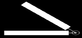
The ejector pad is specially designed to move with a concept of ‘constant angle varying speed’. The ejector pad is placed at the exit doors. Instead of ejecting the seats over the top, the seats are ejected in side ways to some distance and the passengers can deploy their parachute.
Fig1. Design of ejector pad
The ejector pad is constructed with a high power mechanical spring system and hydraulic pistons which produce ejecting power to the pad instead of providing propulsion power to the seats separately. It reduces the propulsive power for each and every seat. There is an only common ejector pad at every exit.
If the piston in the hydraulic system which is placed
under the ejector pad is increases the compression of the
spring increases, which increases the ejecting power. There is a releasing lever at every pad. It holds the ejector pad during the compressing of the springs. For every seat the spring gets
IJSER © 2012 http://www.ijser.org
International Journal of Scientific & Engineering Research, Volume 3, Issue 10, October-2012 2
ISSN 2229-5518
compressed and the releasing lever is opened and the seat gets ejected. The pistons are held over one another. For successive seats the piston height is increased mean while the tension of the spring will increased it will made the seats to ejected with different pressure and it acquire different distances.
The procedure is repeated for all the respective rows
and seats. With the successive increase of piston and compression, relatively the speed of ejecting seats varying.
The varying speed will avoid the collision of the seats. This varying speed system is sited different in other exits by in ascending and descending of speed.
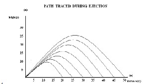
Consider the ejected seat travelled in a parabolic path the time interval (t), the height projected(y), and distance projected(x) can be calculated with the formula.
T=x/ucosα
Y= u sinαt -1/2*gt²
Where in the ejector pad moves at an angle of (α=45º) For velocity of u = 19.81 m/s
The height projected (y) = 10 m The distance projected (x) = 20 m And the time taken = 1.427 sec.
2 path traced during ejection.
Table 1. Height and distance of path trace
Fig
2.2 Design of seat and wear
The seats here employed are similar to the ordinary seats in the aircraft. A simple modification is made in the seats. A ball type bush is placed at bottom stand of the seats it is free to move. At the base of the floor the tracks are designed this is like the rail tracks but placed horizontally. There are gaps provided in the tracks to hold the seats.
The bottom bush of every seat is placed in the gaps
This is the height and distance travelled by successive
seats. By this procedure the collisions of the seats get avoided.
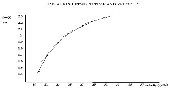
fig 3 relation between time and velocity
In this the each line drawn between the points denotes that each seat has its own path, time and velocity.
Table 2 Relation between time and velocity
between the tracks. The seat cannot be released unless the gaps get elaborated. Additionally the suitable wear for the ejection is attached with the seats it can be closed with a belt. It covers the passenger as a bag. This bag like cover is attached to the seat with pressure buttons. When the seat is ejected out of the aircraft during the parachute get open these pressure buttons get released and the passenger separated from the seat. At the back of the seat the drogue parachute and a parachute and oxygen pouch is placed.
The opening of the parachute is in the hands of the
passenger and it is also connected to a barometric system. The system is ejected along with the seats it calculates the height at which it flies. The height which is suitable for the deployment of the parachute is feuded. Each seat having a sensor unit. When the barometric box read the height suitable for deployment of parachute it send signal to the sensor then the parachute get opened. We cannot teach every passenger how and when to open the parachute and it is impossible. And at the time of ejection nobody was in normal condition to open the parachute at the correct height. These parachutes are designed like the gliders that it tends to the easy landing.
Hence there is no work and confusion for the passengers it is very simple to do such operations.
2.3 Track design
The track is designed like the belt in the tanks. It moves around a cylindrical runner which is connected to a motor. This track provides small ball shaped gap between the pieces. This gap provides space for the seats to fix. The track is able to move around the runner. When the gap reaches the
IJSER © 2012 http://www.ijser.org
International Journal of Scientific & Engineering Research, Volume 3, Issue 10, October-2012 3
ISSN 2229-5518
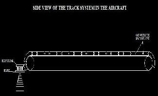
runner it get elaborated and due to limiting friction the seat released from the pad and moved to the ejector pad.
fig4. Side view
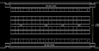
This is the side view of the track system the place at which the seat released to ejector pad is noted.
fig5. Top view
In this track design the right side first row and left side first row only able to move but other rows are fixed. And this rows act as the pavement. When the first row starts moving the seats in the row get start their ejection. After the first row the second row is moved laterally. And replace the place of the first row. This lateral movement is made by the simple hydraulic system. This system moves the corresponding row after finishing of ejection of rows.
There is small run way for each seats for which the
lateral movement is provided between the tracks. When the piston moves the row the seats moved laterally in the tracks then it reached the moving row. After that it gets into the runner and the seats get ejected.
2.4 Ejector system
The ejector system is designed perfectly, and provided with perfect timing sense. This ejector system overcomes the disables of the implementation of ejection seat in civil aircraft. For a civil aircraft the problems are arrived in the form of repair in engine, birds hit and may some other problems in the structural and maintenance problems.
But there is no such a situation like a fighter aircraft face that a missile will attack it. So a civil aircraft may have a minimum 30sec of time for the complete disintegration. Thus this design runs at a maximum time limit of 25 to 30 sec only.
The major problems that are considered as the weight,
propulsive power, cost, mode of application and difficulties.
In this design there is no need to open the top of the aircraft to eject and no propulsion is used to propel the seats thus it reduce the cost and fuel consumption and less usage of power.
Here we are not using the ejection seats used in fighter aircrafts. We are using only the ordinary seats used in the civil aircrafts with some additional equipment like passengers wear, parachute and a small oxygen pouch for the convenient breath of the passengers. This ejection system provides convenient ejection to the passengers rather than that of other ejection system in fighter aircraft. The power for the running motors and the track system are derived from the aircraft power system.
2.5 Timing sector
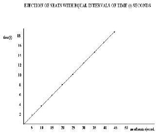
Timing plays an important role in this system. Each seat in the track moves in perfect time sequence. Each seat in the track ejected with an equal interval of time. Within two seconds five seats can be ejected in this system. Each seat accrues its own time of flight, path, speed and distance ejecting. This term avoids the collision of successive seats.
fig 6 Seats ejected at intervals of time
This straight light indicates that the seats ejected with equal intervals of time.
Table3. Time taken for seats to eject
time(t) | 2 | 3 | 6 | 8 | 10 | 12 | 14 | 16 |
number of seats | 5 | 10 | 15 | 20 | 25 | 30 | 35 | 40 |
2.6 Operating system
IJSER © 2012 http://www.ijser.org
International Journal of Scientific & Engineering Research, Volume 3, Issue 10, October-2012 4
ISSN 2229-5518
When the aircraft is at a situation, there is no way to survive then only the ejection system will be operated. All the systems are not only controlled by the pilot but also by the commands from the ground station. At the situation to eject it cannot be done by pilot, he have to get the command signal to operate the system from the ground station. If both the pilot and the ground station commands are executed then only the system get starts.
In spite of the situation the aircraft got away from the
ground control system it disconnects its commending suggestions. Then the operating system is free from the ground station and the full control is only in the hands of pilot.
This type of operating system is to be included
because for the following situation. When in the case of the
aircraft is hijacked by someone if the system has the control only in the aircraft. Then there is a chance of operating the ejection system without the knowledge of pilot. And it create serious problem.
For this situation the system must be controlled by
both ground and pilot. And they can have their own possibility to operate the system when the system is disconnected from any one commending prompt.
2.6 Hydraulic system
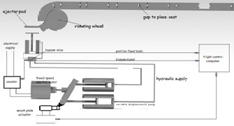
This is an electro hydrostatic machine with dual channel. Essentially it contains elements of motor, pump, by pass valve and piston jack. It is uses a unidirectional fixed speed electric motor to drive a variable displacement pump that controls fluid flow to the hydraulic actuators.
fig 7 Hydraulic system
With the pump rotating at constant speed a separate control mechanism varies the swash plate angle with pump and is therefore able to continuously vary the hydraulic fluid flow. When the swash plate passes through the over centre position, hydraulic fluid flow is reversed. Thus it is changing the direction.
It not needs high power electronic controllers. AC
induction motor connected directly to the aircraft AC supply
This system is designed less sensitive to loads.
And it has rapid start up response.
The swash plate is connected to an actuator which controls the (angle) movement of the swash plate. By increasing the angle the fluid flow will be more at one
condition. Thus it increases the lifting of piston in hydraulic. Where it varies the tension of spring for the successive and varying speed of the seats to be ejected.
All these hydraulic cylinders are connected to a single controlling system where us it reduces weight and it is convenient. Then we can simply place the hydraulic under the ejector pad.
The isolator in the system controls both the electric
motor and the bypass valve. Whereas an electrically controlled
system is always easy to operate and the electric power can be stored.
Isolator controls the speed of the motor and the flow of fluid in the bypass valve. An additional setup called position feedback is droved from hydraulic piston. This can be used to find out the position of the piston.
The major connectivity to all these systems is the flight control computer. Whereas the position feedback and
bypass signal and swash plate actuator signals are feuded and these can be controlled by the programming feuded in the system.
3 PRESSURES AND TEMPERATURE CONDITION
Pressure and temperature plays an important role in the flight. The pressure at the ground and at certain altitude is varies. Therefore the aircraft acts as a pressure vessel. Due to this reason the aircraft is pressurized. If it not pressurized the aircraft will burst due to pressure variation at inside and outside. So the pressure is maintained inside the bulkheads are made in such a manner that to expand at high altitudes and it will came back to normal at low altitudes.
The temperature and pressure variations are
calculated using the hydrostatic equation dp/dh = - ρ g
The pressure and temperature varies with altitude.
Table 4. pressure temperature vs altitude
Altitude hG (m) | Temperature (K) | Pressure N/m2 | Density kg/m3 |
0 | 288.16 | 1.01325*10^5 | 1.2250 |
1000 | 281.66 | 0.89876*10^5 | 1.1117 |
5000 | 255.69 | 0.540448*10^5 | 0.73643 |
10000 | 223.26 | 0.26500*10^5 | 0.41351 |
15000 | 216.66 | 0.12112*10^5 | 0.19475 |
There is problem arise that we cannot open the aircraft at certain altitude. Explanation like that an aircraft is
IJSER © 2012 http://www.ijser.org
International Journal of Scientific & Engineering Research, Volume 3, Issue 10, October-2012 5
ISSN 2229-5518
like a balloon in will be burst when there is a pressure variation at inside and outside atmosphere. The same concept is included in the aircraft.
Let us implement this idea that at sea level altitude say 0m the temperature, pressure and the density is tabulated. At this stage the balloon is just filled with air, here the condition is same at inside and outside of the balloon is same. If we hit it with a pin it does not bust.
Like this the aircraft will not bust at ground level
when there is open in it. Consider at an altitude of 1000m the pressure in aircraft is like the balloon filled with 20-30% of air here also there is no possible of bursting. At 10000m it is like
50-60% and at 15000m like 65-70% of pressure so if we hit it
with a pin the air inside comes out but it does not burst
likewise the aircraft will not burst at these altitudes but there is variation in the stability. Hence this ejection system will be operated at altitude below 15000meters.
You can ask what about for the above altitudes?
For an altitude more than 15000m the pressure variation is high and if we bailed out it will create serious problems to the passengers. When there is a problem in that altitudes the ejection is not possible. If there is failure in engine or some other problems the aircraft will descent because of need of thrust and high drag. So when the aircraft comes into the altitude below 15000m we can operate the ejection system.
4 STABILITY DURING EJECTION
The stability of the aircraft will changes when we open the aircraft at certain altitudes. The stability and control is focused on moments on the airplane and the moment on the control surface.
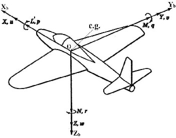
Fig8 Moments of aircraft
Rotational motion about the x, y and z axis is called roll, pitch and yaw and the L’, M and N are rolling, pitching and yawing moment respectively.
Consider a commercial airplane flying at a altitude of
1000m at this altitude the emergency exits are opened for the
ejection at this situation the airplane tends to have stability
variation at X, Y and Z axis that is about rolling, pitching and yawing moment.
In the rotation moment at in stability condition there
is a possibility of the airplane will rotate at any one say left. At this situation if we bailed out the passengers it would not made them collide with each other because rotation about one axis tends it to the centrifugal force which made them through away from the airplane. Same way in pitching the aircraft can pitch up or pitch down at this case seat ejected at front exit reaches a height greater than normal height of ejection because of pitching where the nose is at pitch up. And the seat ejected at rear exit acquires less height than the normal ejection where the tail portion is down and this is vice versa at the pitch down condition.
On considering the yawing moment the stability
variation not much more considered during ejection.
CONCLUSION
As there is increase in air traffic the ejection seats in civil aircraft will play a major role in the safety of passengers. Simple design and perfect timing sense will made this ejection system a valuable one. Surely it will be a mile stone in the development of the ejection seat. This system can be implemented in big commercial aircrafts.
ACKNOWLEDGMENT
I would like to take the opportunity to thank all those who took the time to help me in developing my knowledge.
Firstly, I want to thank my brother as well as assistant
professor Mr Suresh for his guidance and support.
Secondly, I would like to thank my dad Selvaraj, mom Santha and my friend’s prabakaran, Mayakannan, Mathukar, Saravanan and Maheshwari for their kind encouragement and ideas.
REFERENCES
1) United States Air force, “Lockhead F-80shooting star pilot’s
operating manual,” pp. 15-28, November 1950.
2) North Atlan Treaty Organization, “Mikoyan MIG-29 fulcrum pilots flight operating manual,” pp. 1-86, change 4 – 2007.
3) United States Air force, “republic F-105 thunder chief pilot’s
flight operating instructions,” pp. 34 – 2008.
4) Louies A D’Aulerio, “Development of continuous mode sequencing concept for ejection seat,” pp.20, 1983.
5) “Popular science,” pp. 50, 2003.
6) David Shayler, “space rescue,” “ensuring the safety of manned
space craft,” pp. 180, 2009.
7) Jeffrey R. Davies, Robert Johnson, Jan Stepanek, “fundamentals of aerospace medicine,” pp. 104, 2008.
IJSER © 2012 http://www.ijser.org
International Journal of Scientific & Engineering Research, Volume 3, Issue 10, October 2012 6
ISSN 2229 5518
8) Harrunord R.Moy, "advanced concept ejection seat (ASES)
development and qualification," pp. 214, 1973.
9) Kevin Bonsor, " http/ / www.howstuffsworks.com," "how ejection seat works," referred on 9th January 2011.
10) Thomas J Zenobi, Gary F Whitman, "development of back pack survival kit for ejection seats," pp. 15, 1982.
11) Panel, "control in an information rich world: rep ort of the panel on future," pp. 17, 20 03.
IJSER ©2012 http /fwww.llser.org