Number of samples before compression (1)
International Journal of Scientific & Engineering Research Volume 2, Issue 6, June-2011 1
ISSN 2229-5518
Efficient Algorithm for ECG Coding
Ms. Manjari Sharma, Dr. A. K. Wadhwani
Abstract— Electrocardiogram (ECG) data compression algorithm is needed to reduce the amount of data to be transmitted, stored and analyzed, without losing the clinical information content. This work investigates a set of ECG data compression schemes in frequency domain to compare their performances in compressing ECG signals. These schemes are based on transform methods such as discrete cosine transform (DCT), fast fourier transform (FFT), discrete sine transform (DST), and their improvements. An improvement of a discrete cosine transform (DCT)-based method for electrocardiogram (ECG) compression is also presented as DCT-II. A comparative study of performance of different transforms is made in terms of Compression Ratio (CR) and Percent root mean square difference (PRD).The appropriate use of a block based DCT associated to a uniform scalar dead zone quantiser and arithmetic coding show very good results, confirming that the proposed strategy exhibits competitive performances compared with the most popular compressors used for ECG compression. Each specific transform is applied to a pre-selected data segment from the MIT-BIH database and then compression is performed.
Index Terms—Compression, Compression ratio, Cosine transform, ECG, Fourier transform, Frequency domain techniques, PRD, Time domain techniques.
—————————— • ——————————
ODING is useful because it helps reduce the con- sumption of expensive resources, such as hard disk space or transmission bandwidth. On the downside, compressed data must be decompressed to be used and this extra processing may be detrimental to some applica- tions. Basically, a data coding algorithm seeks to minim- ize the number of code bits stored by reducing the re- dundancy present in the original signal. The design of data compression schemes therefore involves trade-offs among various factors including the degree of compres- sion, the amount of distortion introduced (if using a lossy compression scheme) and the computational resources required to compress and uncompress the data. To deal with the huge amount of electrocardiogram (ECG) data for analysis, storage and transmission; an efficient ECG compression technique is needed to reduce the amount of data as much as possible while pre-serving the clinical significant signal for cardiac diagnosis, for analysis of ECG signal for various parameters such as heart rate, QRS-width, etc. Then the various parameters and the compressed signal can be transmitted with less channel capacity. Compression connotes the process of starting with a source of data in digital form (usually either a data stream or a stored file) and creating a representation that uses fewer bits than the original [1]. An effective data compression scheme for ECG signal is required in many practical applications such as ECG data storage, ambula- tory recording systems and ECG data transmission over telephone line or digital telecommunication network for
————————————————
telemedicine. The main goal of any compression tech- nique is to achieve maximum data volume reduction while preserving the significant features [2] and also de- tecting and eliminating redundancies in a given data set. Data compression methods can be classified into two cat- egories: 1) lossless and 2) lossy coding methods. Lossy compression is useful where a certain amount of error is acceptable for increased compression performance. Loss less or information preserving compression is used in the storage of medical or legal records. In lossless data com- pression, the signal samples are considered to be realiza- tions of a random variable or a random process and the entropy of the source signal determines the lowest com- pression ratio that can be achieved. In lossless coding the original signal can be perfectly reconstructed. For typical biomedical signals lossless (reversible) compression me- thods can only achieve Compression Ratios (CR) in the order of 2 to 1. On the other hand lossy (irreversible) techniques may produce CR results in the order of 10 to 1. In lossy methods, there is some kind of quantization of the input data which leads to higher CR results at the ex- pense of reversibility. But this may be acceptable as long as no clinically significant degradation is introduced to the encoded signal. The CR levels of 2 to 1 are too low for most practical applications. Therefore, lossy coding me- thods which introduce small reconstruction errors are preferred in practice. In this paper we review the lossy biomedical data compression methods.
Biomedical signals can be compressed in time domain, frequency domain, or time-frequency domain. ECG data compression algorithms have been mainly classified into three major categories [3]: 1) Direct time-domain tech- niques, e.g., turning point (TP), amplitude-zone-time epoch coding (AZTEC) [4], coordinate reduction time encoding system (CORTES) and Fan algorithm. 2) Trans- formational approaches [3], e.g., discrete cosines trans- formation (DCT), fast fourier transform (FFT), discrete
IJSER © 2011 http://www.ijser.org
International Journal of Scientific & Engineering Research Volume 2, Issue 6, June-2011 2
ISSN 2229-5518
sine transform (DST), wavelet transform (WT) etc. 3) Pa- rameter extraction techniques, e.g., Prediction and Vector Quantization (VQ) methods [2]. The time domain tech- niques which are based on direct methods were the earli- er approaches to biomedical signal compression. Trans- form Coding (TC) is the most important frequency- domain digital waveform compression method.
When we compare these methods we find that direct data compression is a time domain compression algo- rithm which directly analyses samples where inter-beat and, intra-beat correlation is exploited. These algorithms suffer from sensitiveness to sampling rate, quantization levels and high frequency interference. It fails to achieve high data rate along with preservation of clinical informa- tion [5]. In Transform based technique [6] compressions are accomplished by applying an invertible orthogonal transform to the signal. Due to its de-correlation and energy compaction properties the transform based me- thods achieve better compression ratios [7]. In transform coding, knowledge of the application is used to choose information to discard, thereby lowering its bandwidth. The remaining information can then be compressed via a variety of methods. When the output is decoded, the re- sult may not be identical to the original input, but is ex- pected to be close enough for the purpose of the applica- tion. In parameter extraction methods a set of model pa- rameters/features are extracted from the original signal (model based) which involves methods like Linear term prediction (LTP) and analysis by synthesis.
In this paper different transforms like DCT, FFT, DST and are studied for ECG signal compression. A threshold based algorithm is proposed to achieve better compres- sion as DCT-II.
Compression of electrocardiography (ECG) is necessary for efficient storage and transmission of the digitized ECG signals. A typical ECG monitoring device generates a large amount of data in the continuous long-term (24-48 hours) ambulatory monitoring tasks. For good diagnostic quality, up to 12 different streams of data may be ob- tained from various sensors placed on the patient’s body. The sampling rates of ECG signals are from 125Hz to
500Hz, and each data sample may be digitized into 8 to 12 bits binary number. Even with one sensor at the lowest sampling rate of 125 Hz and 8-bit encoding, it generates data at a rate of 7.5KB per minute and 450KB per hour. For a sampling rate of 500Hz and 12-bit encoding record- ing, it generates data at a rate of 540KB per minute and
30MB per hour. The data rate from 12 different sensors totally will generate 12 times amount of data and it is enormously big. Besides, recording over a period of time as long as 24 hours maybe needed for a patient with irre- gular heart rhythms . The monitor device such as Holter must have a memory capacity of about 400-800 MB for a
12-lead recording, but such a big memory cost may rend-
er a solid-state commercial Holter device impossible. Thus, efficient ECG data compression to dramatically reduce the data storage capacity is a necessary solution. On the other hand, it makes possible to transmit ECG data over a telephone line from one cardiac doctor to another cardiac doctor to get opinions.
Before studying the various algorithms it is important to understand the criteria on the basis of which results are compared. The evaluation of performance for testing ECG compression algorithms includes three components: compression efficiency, reconstruction error and compu- tational complexity. The compression efficiency is given by compression ratio (CR). The compression ratio and the reconstruction error are usually dependent on each other. The computational complexity component is part of the practical implementation consideration [8], [9]. In present work we have tested the data on the basis of Compression ratio CR and Percent root mean square difference PRD.
This is one of the most important parameters in data compression algorithms which specifies the amount of compression. A large value of this ratio shows success of any algorithm. Compression Ratio (CR) is defined as the ratio between the rates of the compressed signal (in terms of bits per second) to the rate of the original signal. A data compression algorithm must also represent the data with acceptable fidelity while achieving high CR, given by (1).![]()
Number of samples before compression (1)
Number of samples after compression
One of the most difficult problems in ECG compression applications and reconstruction is defining the error crite- rion. The purpose of the compression system is to remove redundancy and irrelevant information. Consequently the error criterion has to be defined so that it will measure the ability of the reconstructed signal to preserve the relevant information. Since ECG signals generally are compressed with lossy compression algorithms, we have to have a way of quantifying the difference between the original and the reconstructed signal, often called distortion. Dif- ferent objective error measures namely; root mean square error (RMSE), percentage root mean difference (PRD), signal to noise ratio (SNR) are used for calculation of re- construction error. The most prominently used distortion measure is the Percent Root mean square Difference (PRD) [10] that is given by (2)
IJSER © 2011 http://www.ijser.org
International Journal of Scientific & Engineering Research Volume 2, Issue 6, June-2011 3
ISSN 2229-5518
![]()
L [x (n)-x'(n)]2
![]()
vk =
LN-1 xn cos
(2n+1)kn
, k=1, 2,……, (N-1) (4)![]()
::: n:::
L
2 (2)
![]()
![]()
N n=O 2N
L n:::[x(n)]
where x(n) is the original signal, x’(n) is the recon-
structed signal and Lb is the length of the block or se-
where vk is the kth DCT coefficient. The inverse dis-
crete cosine transform (IDCT) of v is given by (5).
quence over which PRD is calculated. PRD provides a![]()
![]()
![]()
x = 1 v + 2
k =1 cos
![]()
(2n+1)kn
, n=0, 1, 2,……(N-1)
numerical measure of the residual root mean square (rms)
error.
N N 2N
(5)
In transform coding, knowledge of the application is used to choose information to discard, thereby lowering its bandwidth. The remaining information can then be com- pressed via a variety of methods. When the output is de- coded, the result may not be identical to the original in- put, but is expected to be close enough for the purpose of the application. Transform Coding (TC) is the most im- portant frequency-domain digital waveform compression method. The key is to divide the signal into frequency components and judiciously allocate bits in the frequency domain. In most TC methods, the input signal is first di- vided into blocks of data and each block is linearly trans- formed into the frequency domain. Transformation me- thods involve processing of the input signal by a linear orthogonal transformation and encoding of output using an appropriate error criterion. For signal reconstruction an inverse transformation is carried out and the signal is recovered with some error. Thus transformation tech- niques involve preprocessing the input signal by means of linear orthogonal transformation and properly encod- ing the transformed output (expansion coefficients) and reducing the amount of data needed to adequately represent the original signal. Various orthogonal trans- formations include Karhunen-Loeve Transform (KLT), Discrete Cosine Transform (DCT), Fast Fourier Transform (FFT), Discrete Sine Transform (DST), and WAVELET transforms etc.
There exist fast algorithms, Order (N log N), to com- pute the DCT .Thus, DCT can be implemented in a com- putationally efficient manner. Two recent image and vid- eo coding standards, JPEG and MPEG, use DCT as the main building block.
A discrete cosine transform (DCT) expresses a se- quence of finitely many data points in terms of a sum of cosine functions oscillating at different frequencies [11]. DCTs are important to numerous applications in science and engineering, from lossy compression of audio (e.g. MP3) and images (e.g. JPEG) (where small high- frequency components can be discarded), to spectral me- thods for the numerical solution of partial differential equations. The use of cosine rather than sine functions is critical in these applications. For compression, it turns out that cosine functions are much more efficient whereas for differential equations the cosines express a particular choice of boundary conditions [12]. In particular, a DCT is a Fourier-related transform similar to the discrete Fourier transform (DFT), but using only real numbers. DCTs are equivalent to DFTs of roughly twice the length, operating on real data with even symmetry (since the Fourier trans- form of a real and even function is real and even), where in some variants the input and/or output data are shifted by half a sample.![]()
Discrete Cosine Transform is a basis for many signal and image compression algorithms due to its high de- correlation and energy compaction property [7]. A dis- crete Cosine Transform of N sample is defined as in (6):
In this work we have compared the performance of
F(u) =
(u) LN-1 f(x)cos n(2x+1)u
four different frequency domain transformation methods for ECG compression and then their performance is eva- luated. The various compression techniques have been discussed below:![]()
![]()
N x=O 2N
u=0,1,……..,N-1,
1
(6)
The Discrete Cosine Transform (DCT) was developed to approximate Karhunen-Loeve Transform (KLT) when there is high correlation among the input samples, which is the case in many digital waveforms including speech, music, and biomedical signals.
The DCT v= [v0 v1………….vN-1]T of the vector x is de-![]()
where C(u) = 2 for u =0
=1 otherwise.
The function f(x) represents the value of xth samples of input signals [7]. F(u) represents a DCT coefficients. The inverse DCT is defined in similar fashion as in (7):
fined as follows:![]()
f(x) = LN-1
(u)F(u)cos
(7)
vO= :::
N-1
n=O n
(3)![]()
![]()
N u=O 2N
x=0, 1,… N-1.
IJSER © 2011 http://www.ijser.org
International Journal of Scientific & Engineering Research Volume 2, Issue 6, June-2011 4
ISSN 2229-5518
A fast Fourier transform (FFT) [13] is an efficient algo- rithm to compute the discrete fourier transform (DFT) and it’s inverse [14]. There are many distinct FFT algo- rithms involving a wide range of mathematics, from sim- ple complex-number arithmetic to group theory and number theory. A DFT decomposes a sequence of values into components of different frequencies but computing it directly from the definition is often too slow to be practic- al. An FFT is a way to compute the same result more quickly. Computing a DFT of N points in the naive way, using the definition, takes O(N2) arithmetical operations [15], while an FFT can compute the same result in only O(N log N) operations. The difference in speed can be substantial, especially for long data sets where N may be in the thousands or millions—in practice, the computa-
ent frequencies and amplitudes. Like the discrete Fourier transform (DFT), a DST operates on a function at a finite number of discrete data points. The obvious distinction between a DST and a DFT is that the former uses only sine functions, while the latter uses both cosines and sines (in the form of complex exponentials). However, this visi- ble difference is merely a consequence of a deeper distinc- tion: a DST implies different boundary conditions than the DFT or other related transforms [17].
Formally, the discrete sine transform is a linear, invert- ible function F: RN -> RN (where R denotes the set of real numbers), or equivalently an N × N square matrix. There are several variants of the DST with slightly modified definitions. The N real numbers x0,…, xN-1 are trans- formed into the N real numbers X0, ..., XN-1 according to (10):
N-1 n
![]()
tion time can be reduced by several orders of magnitude
in such cases, and the improvement is roughly propor-
tional to N / log (N). This huge improvement made many
DFT-based algorithms practical; FFTs are of great impor-
tance to a wide variety of applications, from digital signal
Xk = Ln=O xn sin N+1 (n + 1)(k + 1)
k=0,……N-1
(10)
processing and solving partial differential equations to algorithms for quick multiplication of large integers. The most well known FFT algorithms depend upon the facto- rization of N, but there are FFTs with O (N log N) com- plexity for all N, even for prime N. Many FFT algorithms
The most common variant of discrete cosine transform is
the type-II DCT [18]. The DCT-II is typically defined as a
real, orthogonal (unitary), linear transformation by the
formula in (11):
only depend on the fact that is an Nth primitive root of![]()
II 2 -ok,o
N-1 n 1
unity, and thus can be applied to analogous transforms![]()
![]()
k = Ln=O xn cos
n k (11)
N 2
over any finite field, such as number-theoretic transforms.
for N inputs xn and N outputs k k O
Fast Fourier Transform is a fundamental transform in
II, where o
Kronecker delta (= 1 for k = 0 and = 0 otherwise).
is the
digital signal processing with applications in frequency
analysis, signal processing etc [7]. The periodicity and
symmetry properties of DFT are useful for compression. The uth FFT coefficient of length N sequence {f(x)} is de- fined as in (8):
F(u) = LN-1 f(x)e-j2nux/N
u=0,1,….N-1.
DCT-II can be viewed as special case of the discrete fourier transform (DFT) with real inputs of certain sym- metry [19]. This viewpoint is fruitful because it means that any FFT algorithm for the DFT leads immediately to a corresponding fast algorithm for the DCT-II simply by discarding the redundant operations.
The discrete Fourier transform of size N is defined by
(12):
And its inverse transform is calculated from (9):
Xk = LN -1 xn
(12)
1 N-1
j2nux/N
where wN =e-2ni/N is an Nth primitive root of unity. In
f(x) = N Lu=O f(x)e
x=0,1,….N-1
(9)
order to relate this to the DCT-II, it is convenient to choose a different normalization for the latter transform [19] as in (13):
N-1 n 1
Discrete sine transform (DST) [16] is a Fourier-related![]()
![]()
k = 2 Ln=O xn cos
n k (13)
N 2
transform similar to the discrete Fourier transform (DFT), but using a purely real matrix. It is equivalent to the im- aginary parts of a DFT of roughly twice the length, oper- ating on real data with odd symmetry (since the Fourier transform of a real and odd function is imaginary and odd), where in some variants the input and/or output data are shifted by half a sample. Like any Fourier-related
This normalization is not unitary, but it is more direct-
ly related to the DFT and therefore more convenient for
the development of algorithms. Of course, any fast algo-
rithm for Ck trivially yields a fast algorithm for II al-
though the exact count of required multiplications de- pends on the normalization. In order to derive k from
the DFT formula, we can use the identity
2l 4N-2l to write (14):
transform, discrete sine transforms (DSTs) express a func-
tion or a signal in terms of a sum of sinusoids with differ-
2cos(rrlIN)=w4N + w4N
IJSER © 2011 http://www.ijser.org
International Journal of Scientific & Engineering Research Volume 2, Issue 6, June-2011 5
ISSN 2229-5518
![]()
![]()
k = 2 LN-1 xn cos n k
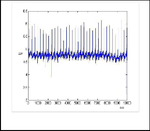
The plot for compressed ECG by DCT is shown in Fig. 2.
2n+1)k +L x
w(4N-2n-1)k
= LN-1 xn (
N-1
n
n=O w4N
n=O 4N
= L4N-1 x n
nk (14)
n=O w4N
where x n is a real-even sequence of length 4N, defined
as follows for 0 ::; n < N:
x 2n = x4N--(2n+1) = xn (15)
Thus, the DCT-II of size N is precisely a DFT of size
4N, of real-even inputs, where the even-indexed inputs
are zero.
The various compression techniques DCT, FFT, DST algo- rithms are compared with PRD and Compression ratio CR and best suitable is considered. A threshold based algorithm is proposed to achieve better compression as DCT-II. The algorithms are performed on MIT-BIH data- base shown in Fig. 1.
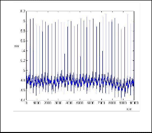
Fig 2. The ECG signal after DCT coding
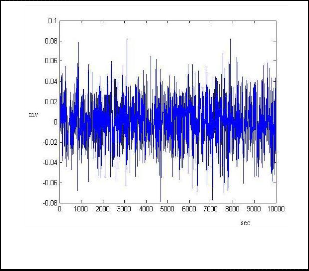
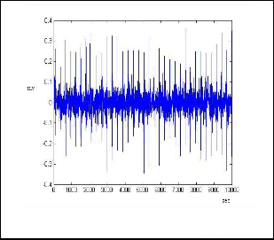
The error signal after DCT coding is shown in Fig. 3.
Fig. 1.The ECG signal before coding
Fig.3. The Error signal after DCT coding
1. Separate the ECG components into three compo- nents x, y, z.
2. Find the frequency and time between two sam- ples.
3. Find the DCT of ECG signal and check for DCT coefficients (before compression) =0, increment the counter A if it is between +0.22 to -0.22 and assign to Index=0.
4. Check for DCT coefficients (after compression) =0, increment the Counter B.
5. Calculate inverse DCT and plot decompression, error.
6. Calculate the compression ratio CR and PRD.
1. Separate the ECG components into three compo- nents x, y, z.
2. Find the frequency and time between two sam- ples.
3. Find the FFT of ECG signal and check for FFT coefficients (before compression) =0, increment the counter A if it is between +25 to-25 and assign to Index=0.
4. Check for FFT coefficients (after compression) =0, increment the Counter B.
5. Calculate inverse FFT and plot decompression, er- ror.
6. Calculate the compression ratio CR and PRD.
IJSER © 2011 http://www.ijser.org
International Journal of Scientific & Engineering Research Volume 2, Issue 6, June-2011 6
ISSN 2229-5518
The plot for compressed ECG by FFT is shown in Fig. 4.
The plot for compressed ECG by DST is shown in Fig. 6.
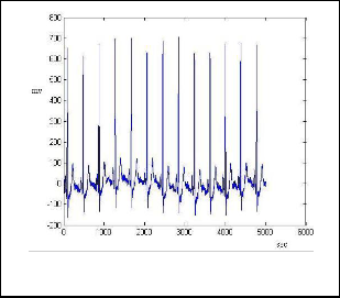
Fig.4. The ECG signal after FFT coding
Fig.6. The ECG signal after DST coding
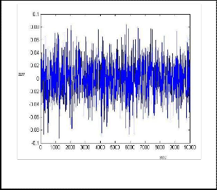
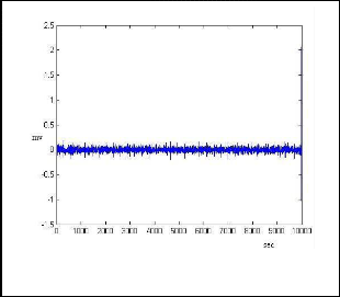
The error signal after FFT coding is shown in Fig. 5.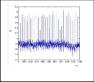

The error signal after DST is shown in Fig. 7.
Fig.5. The Error signal after FFT coding
Fig.7. The Error signal after DST coding
1. Separate the ECG components into three compo- nents x, y, z.
2. Find the frequency and time between two sam- ples.
3. Find the DST of ECG signal and check for DST coefficients (before compression) =0, increment the counter A if it is between +15 to-15 and assign to Index=0.
4. Check for DST coefficients (after compression) =0, increment the Counter B.
5. Calculate inverse DST and plot decompression, er- ror.
6. Calculate the compression ratio CR and PRD.
1. Partition of data sequence x in Nb consecutive blocks bi, i =0, 1,…….., Nb-1, each one with Lb sam- ples.
2. DCT computation for each block.
3. Quantization of the DCT coefficients.
4. Lossless encoding of the quantized DCT coeffi-
cients.
Increasing the block size increases the CR and the DCT
computing time. Various results show that increasing the
block size above a certain point results in a very modest
CR gain, while the processing time increases. The type II
DCT is commonly used for data compression due to its
greater capacity to concentrate the signal energy in few
transform coefficients.
IJSER © 2011 http://www.ijser.org
International Journal of Scientific & Engineering Research Volume 2, Issue 6, June-2011 7
ISSN 2229-5518
The algorithm is explained in detail as:
1. Let bi[n], n=0,1,…,Lb-1,represent the Lb values in block bi.
2. The one-dimensional DCT-II of this block gene- rates a transformed block Bi constituted by a se- quence of Lb coefficients Bi[m], m=0,1,…..Lb-1,given by (16):![]()
2 LL-1
(2n+1)mn
Bi [m] =
cm Ln=O bi [n]cos![]()
2LL
(16)
m = 0,1, … Lb - 1
where cm=1 for 1::; m ::; Lb-1 and co=(1/2)(1/2).
The DCT can be seen as a one-to-one mapping for
N point vectors between the time and the frequen-
cy domains. The coefficient Bi[0],which is directly related to the average value of the time-domain
block is called DC coefficient and the remaining coefficients of a block are called AC coefficients.
Given Bi, bi can be recovered by applying the in- verse DCT-II:
Fig. 8. The ECG signal after DCT-II coding
The error signal after DCT-II coding is shown in Fig. 9.![]()
2 LL-1
(2n+1)mn
bi [n] =
L cm Bi [m]cos![]()
2LL
(17)
n=0,1,….Lb-1.
3. To quantize Bi we use quantization vector q. Each element q[n], n=0,1,….Lb-1,of q is a positive integer in a specified interval and represents the quantiza- tion step size for the coefficient Bi[n].The elements
Bz [n]of the quantized DCT block Bz obtained by the
following operation:
B [n] = B [n]//q[n] , n=0,1,….Lb-1 (18)
i=0,1,…..Nb-1
where // represents division followed by round- ing to the nearest integer.
4. The lossless encoding of the quantized DCT coeffi- cients involves run-length encoding, because the quantization normally generates many null values followed by an entropy encoder.
The plot for compressed ECG by DCT-II is shown in Fig.
8.
Fig.9. The Error signal after DCT-II coding
Since signal recording conditions and noise levels vary from study to study, a thorough comparison of the coding methods is very difficult to make. But, frequency-domain coding methods produce higher coding results than time- domain coding methods. We used data in the MIT-BIH database to test the performance of the four coding tech- niques. The ECG data is sampled at 360Hz and the resolu- tion of each sample is 11 bits/samples that total bit rate is
3960bps. The amount of compression is measured by CR and the distortion between the original and reconstructed signal is measured by PRD. The comparison table shown in Table 1, details the resultant compression techniques. This gives the choice to select the best suitable compres- sion method. A data compression algorithm must represent the data with acceptable fidelity while achiev-
IJSER © 2011 http://www.ijser.org
International Journal of Scientific & Engineering Research Volume 2, Issue 6, June-2011 8
ISSN 2229-5518
ing high CR. As the PRD indicates reconstruction fidelity; the increase in its value is actually undesirable. Although DCT-II provides maximum CR, but distortion is more. So a compromise is made between CR and PRD.
TABLE 1
COMPARISON OF COMPRESSION TECHNIQUES
Method | Compression Ratio | PRD |
DCT | 91.6800 | 0.8392 |
FFT | 89.5723 | 1.0237 |
DST | 70.4073 | 1.1967 |
DCT-II | 94.28 | 1.5729 |
Considering that the number of electrocardiogram records annually numbers in the millions and the use of sending electrocardiogram records over telephone lines for remote analysis is increasing, the need for effective electrocardiogram compression techniques is great. Many existing compression algorithms have shown some suc- cess in electrocardiogram compression; however, algo- rithms that produce better compression ratios and less loss of data in the reconstructed data are needed. This paper has provided an overview of several compression techniques and has formulated new algorithms that should improve compression ratios and lessen error in the reconstructed data. This has allowed comparing vari- ous compression schemes and analyzing reconstructed electrocardiogram records through a graphic interface, without detailed knowledge of the mathematics behind the compression algorithm.
Transform based techniques because of their high com- pression ability have gained popularity. In this paper the preprocessed signal is transformed to get the decorrelated coefficients. The thresholding or quantization of trans- formed coefficients gives the actual compression, which is lossy one. But it has good performance and low computa- tional cost. Among the four techniques presented, DST provides lowest CR and distortion is also high. FFT im- proves CR and lowers PRD. So FFT is better choice than DST. Next is DCT which gives higher CR upto 91.68 with PRD as 0.8392. But DCT-II provides an improvement in terms of CR of 94.28 but PRD increases up to 1.5729. Thus an improvement of a discrete cosine transform (DCT)- based method for electrocardiogram (ECG) compression
is presented as DCT-II. The appropriate use of a block based DCT-II associated to a uniform scalar dead zone quantiser and arithmetic coding show very good results, confirming that the proposed strategy exhibits competi- tive performances compared with the most popular com- pressors used for ECG compression.
The authors would like to thank UGC, New Delhi for providing financial support to carry out this research work.
[1] Pranob K. Charles and Rajendra Prasad K. (2011): A Contemporary Approach For ECG Signal Compression Using Wavelet Transforms. Signal and Image Processing: An International Journal (SIPIJ). Vol. 2, No. 1, 178-183.
[2] Yucel Kocyigit, Mehmet Korurek and Bekir Karlik (1999): ECG Data Compression by Artificial Neural Networks. In ELEC0’99 International Conference On Electrical And Electronics Enginering. E01.44/D-10, 338-339.
[3] S. Jalaleddine, C. Hutchens, R. Stratan, and W. A. Coberly (1990): ECG data compression techniques-A unified approach. IEEE Trans. Biomed. Eng., 37, 329-343.
[4] J. R. Cox, F. M. Nolle, H. A. Fozzard and G. C. Oliver (1968), AZTEC: A preprocessing scheme for real time ECG rhythm analysis. IEEE Tran. Biomed. Eng., vol-BME-15, 128-129.
[5] M. Sabarimalai Manikandan and S. Danpat (2006): Wavelet Threshold based ECG Compression using USZZQ and Huffman Coding of DSM. In Science Direct Biomedical Signal Processing and Control. 261-270.
[6] B. R. S. Reddy and I. S. N. Murthy (1986): ECG data compression using
Fourier descriptors, IEEE Trans. Bio-med. Eng., BME-33, 428-433.
[7] Mrs. S. O. Rajankar and Dr. S. N. Talbar (2010): An Optimized Trans- form for ECG Signal Compression. In Proc. Of Int .Conf. on Advances in Computer Science, 94-96.
[8] Shang-Gang Miaou, Heng-Lin Yen, Chih-Lung Lin (2002): Wavelet based ECG compression using Dynamic vector Quantization with Tree Code vectors in single codebook. In IEEE Transaction on Biomedical Engineering, vol. 49, no. 7, pp. 671-680.
[9] R.shanta selva Kumari, V Sadasivam (2007): A novel algorithm for wavelet based ECG signal coding. Science Direct Computers and Electrical Engineering, 33, pp. 186-194.
[10] J. Abenstein and W. Tompkins (1982): A new data-reduction algorithm for real time ECG analysis. IEEE Tran. On Biomed. Engg., 29(BME-1):4,
3-8.
[11] N. Ahmed, T. Natarajan and K. R. Rao (1974): Discrete Cosine Trans- form. IEEE Trans. Trans. On Computers. C-23, 90-93.
[12] K. R. Rao and P. Yip (1990): Discrete cosine transform – algorithms, advantages, applications, San Diego: Academic Press.
[13] M. Clausen and U. Baum (1993): Fast Fourier Transforms. BI-Wiss.-Verl. [14] L. Auslander, E. Feig and S. Winograd (1984): Abelian Semi-simple Algebras and Algorithms for the Discrete Fourier Transform. In Ad-
vances in Applied Mathematics.5, 31-55.
[15] Tinku Acharya and Ajoy K. Roy. Image Processing Principles and
Applications. John Wiley.
[16] S. Chan and K. Ho (1990): Direct Methods for computing discrete sinu-
IJSER © 2011 http://www.ijser.org
International Journal of Scientific & Engineering Research Volume 2, Issue 6, June-2011 9
ISSN 2229-5518
soidal transforms. IEEE Proceedings, 137, 433-442.
[17] G. Steidl and M. Tasche (1991): A Polynomial approach to Fast algo- rithms for Discrete Fourier –cosine and Fourier-sine Transforms. In Ma- thematics in Computation, 56 (193), 281-296.
[18] E. Feig and S. Winograd (1992): Fast Algorithms for Discrete Cosine
Trnsforms. IEEE Tran. On Signal Processing.vol-40(9), pp 2174-2193.
[19] Xuancheng Shao and Steven G. Johnson (May 10, 2007): Type-II/III DCT/DST algorithms with reduced number of arithmetic operations.
Preprint submitted to Elsevier.
IJSER © 2011 http://www.ijser.org