International Journal of Scientific & Engineering Research, Volume 4, Issue 4, April‐2013 1709
ISSN 2229‐5518
Efficient Reed Solomon Decoder Based on pRiBM Algorithm for Effective Digital Signal Reception
R. Shanmuga Priya1, A. Beno2
1PG Scholar, VLSI Design, 2Assitant Professor, ECE Department,
1&2Dr. Sivanthi Aditanar College of Engineering, Tiruchendur.
—————————— ——————————
In the present Digital Communication systems, it is highly possible that the data or message may get corrupted during transmission and reception through a noisy channel medium. The environmental interference and the physical defects in the medium are the main causes for the data or message corrup‐ tion in the communication medium, which leads to the injec‐ tion of random bits into the original message and corrupt the original message. To have a reliable communication through noisy medium error correcting codes (ECC) [1], [2], [3], [4] has to be used.
The error correction is based on mathematical formulas,
which are used by error correcting codes (ECC). Error correc‐ tion takes place by adding parity bits to the original message bits during transmission of the data. Because of the addition of parity bits to message bits, the size of the original message bits becomes longer. Now this longer message bits is called “Codeword”. This codeword is received by the receiver at the destination, and could be decoded to retrieve the original mes‐ sage bits [5], [6].
Reed Solomon Codes are used for both encoding and de‐ coding purposes. These codes are defined as RS (n, k) with m bit symbols. The RS codes detect and correct the errors in the symbols. Reed Solomon codes follow the Galois Field (GF) mathematic properties for encoding and decoding techniques [7], [8], [9].
In this paper, a RS decoder using pRiBM algorithm is pro‐
posed with the aim of reducing the delay and improving the speed for the RS (255,223) decoder [10], [11], [12]. The RS (255,223) code uses a primitive polynomial which is,
p(x) = 1+α2+ α3+α4+ α8 over GF(28) (1)
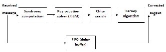
The RS decoding is done in three levels. The very first step in the decoding process is to calculate the syndrome values which are used to check, whether the errors are occurred or
not. The second step includes error location which tells us where the error is present. This is done by inversion‐free Ber‐ lekamp Massey algorithm and the third one is the error evalu‐ ation which corrects the error. For error correction Chien search and Forney algorithm are used. The decoder has the capability of correcting up to t errors where n=k+2t [13], [14], [15].
The decoder has three main functions: 1. Syndrome com‐
Fig .1 Reed Solomon Decoder
putation 2. Key equation solver 3. Chien search and Forney algorithm.
The architecture for Syndrome Computation is shown in fig. 2. The input to this module is the corrupted codeword, r(x). The equations for the codeword, received bits and the error bits are given in the below equations.
Codeword equation
c(x) = c0 + c1x + c2x2 + ... + cn‐1xn‐1 (2) Received bits equation
r(x) = r0 + r1x + r2x2 + ... + rn‐1xn‐1 (3) Error bits equation
e(x) = e0 + e1x + e2x2 + ... + en‐1xn‐1 (4)
IJSER © 2013 http://www.ijser.org
International Journal of Scientific & Engineering Research, Volume 4, Issue 4, April‐2013 1710
ISSN 2229‐5518
Thus, the final transmitted data polynomial equation is
given as
r(x) = c(x) + e(x) (5)
Here the input received symbols are divided by the gen‐ erator polynomial. The result should be zero. The parity is placed in the codeword to ensure that code is exactly divisible by the generator polynomial. If there is a remainder, then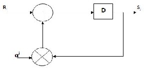
Fig .2 Syndrome Computation Architecture
there are errors. The remainder is called the syndrome.
The sy n1romes Sj can be defined as
After the Key Equation Solver (KES) block, the error loca‐ tor polynomial σ(x) and the error value polynomial ω(x) are fed into the Chien search block and Forney block, respectively. The architecture for Chien search is shown in figure 4 and the
architecture for Forney algorithm is shown in fig. 5.
S j ri
i 0
i j
for (1 j 2t) (6)
The job of the Chien Search block is to calculate the roots of the error‐locator polynomial of degree t in GF (2m), where t is the maximum number of errors that can be corrected in the
Once the syndromes are found, the next step is to deter‐ mine the coefficients for the error location polynomial. For this, pipelined Reduced inversion‐free Berlekamp Massey al‐ gorithm (pRiBM) is used. The architecture for this is shown in fig. 3. This stage involves the solving of the 2t syndrome poly‐ nomials, formed in the previous stage. These polynomials have v unknowns, where v is the number of unknown errors prior
to de‐ cod‐ ing.
RS code. When the result of an evaluation of error location
polynomial equals 0, it indicates an error in the (n‐i)th symbol in the codeword.
The Forney algorithm block works in parallel with the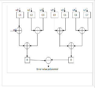
Chien search block to calculate the magnitude of the error symbol at each location. A polynomial is formed by combining the error locations (as powers of x) with the error magnitudes (as powers of α). The codeword is corrected by combining this
Fig .3 pRiBM Architecture
the error polynomial can be expressed as
E(x) = Y1xi1+ Y2xi2 + ........ + Yvxiv (7)
I
f the un‐ kno wn loca‐ tions are,
i1, i2,
…….
,iv
Fig .5 Forney Block
polynomial with the original codeword polynomial. The result
where Y1 is the magnitude of the 1st error at location i1.
IJSER © 2013 http://www.ijser.org
International Journal of Scientific & Engineering Research, Volume 4, Issue 4, April‐2013 1711
ISSN 2229‐5518
is the corrected codeword.
Reed Solomon decoders are often based on Finite field also known as Galois field. An RS code with 8 bit symbols will use a GF (28) consisting of 256 symbols.
Addition and subtraction of elements of GF (28) are simple XOR operations of the two operands. Each of the elements in the GF is first represented as a corresponding polynomial. The addition or subtraction operation is then represented by the XOR operation of the coefficient of corresponding polynomi‐ als.
The critical arithmetic unit in the RiBM architecture is the GF multiplier. So to improve the clock frequency, efficient GF multiplier should be designed. Since the Chien search and Forney algorithm also uses the Galois field arithmetic, Galois field multipler is used. The basic difference between Galois field multiplication and general binary multiplication comes from the fact that the Galois field is finite. Hence the result of any operation should lie in the same field. In binary multipli‐ cation of two m bit data the result may go beyond m bits. But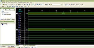
Fig .7 Simulation result for Forney algorithm
in case of Galois field as the field is defined as the set of m bit symbols, the result of any operation should be of m bit.
The simulation result obtained for Forney algorithm is shown in fig. 7.
In this project, Berlekamp Massey algorithm is used as key equation solver in the Reed Solomon Decoder. The Reed Solomon Decoder used here is RS (255,223). The decoder is designed and simulated using Verilog code. The delay ob‐ tained for syndrome computation without pipelining is 18.536 ns and the delay is reduced to 15.73 ns through pipelining. The delay obtained for RiBM algorithm is 57.644 ns and the
delay obtained for pRiBM algorithm is 49.705 ns. The delay obtained for Chien Search algorithm and Forney algorithm is
18.740 ns and 15.289 ns. Therefore the total delay obtained without pipelining is 110.209 ns and with pipelining is 99.464 ns. Thus the Reed Solomon Decoder using pRiBM algorithm is more efficient than Reed Solomon Decoder using RiBM algo‐ rithm.
[1] Arun Raghupathy, Member, IEEE, and K. J. R. Liu, Senior Member, “Algorithm‐Based Low‐Power/High‐Speed Reed–Solomon Decoder Design”, IEEE Transaction on circuits and systems ‐ II: analog and digital signal processing, vol. 47, no. 11, November 2000.
[2] Cardarilli G C, Pontarelli S, et.al, ”Concurrent Error Detection in Reed–Solomon Encoders and Decoders” IEEE transactions on very large scale integration (VLSI) systems vol. 15, no. 7, July 2007.
Fig .4 Chien Search Block
[3] Garcia‐Herrero F, Valls J, et.al, “High speed RS(255, 239) decoder based on LCC decoding,” Circuits System Signal Process., vol. 30, no.
6, pp. 1643–1669. June 2011.
[4] Jiangli Zhu, Student Member, IEEE, and Xinmiao Zhang, Member, IEEE, “Efficient VLSI Architecture for Soft‐Decision Decoding of Reed–Solomon Codes”, IEEE Transaction on circuits and systems ‐ I: regular papers, vol. 55, no. 10, November 2008.
[5] Jih‐Chiang Yeo, Huai‐Yi Hsu, et.al, “A scalable Reed‐Solomon de‐
coding processor based on unified finite‐field processing element de‐ sign” Graduate Institute of Electronic Engineering and Department of Electrical Engineering, National Taiwan University, 2004.
[6] Jun Ma, Student Member, IEEE, Alexander Vardy, Fellow, IEEE, and Zhongfeng Wang, Senior Member, “Low‐Latency Factorization Ar‐ chitecture for Algebraic Soft‐Decision Decoding of Reed–Solomon Codes”, IEEE transactions on very large scale integration (VLSI) sys‐ tems, vol. 15, no. 11, November 2007.
[7] Kihoon Lee, Han‐Gil Kang, et.al, “A High‐Speed Low‐Complexity Concatenated BCH Decoder Architecture for 100 Gb/s Optical Com‐ munications”,. Springer Science + Business Media, August 2010.
[8] Koetter R and Vardy A, “Algebraic soft‐decision decoding of Reed– Solomon codes,” IEEE Transaction on Information. Theory, vol. 49, no. 11, pp. 2809–2825, November 2003.
[9] Lui W, Rho J, and Sung W, “Low‐power high‐throughput BCH error
IJSER © 2013 http://www.ijser.org
International Journal of Scientific & Engineering Research, Volume 4, Issue 4, April‐2013 1712
ISSN 2229‐5518
correction VLSI design for multi‐level cell NAND flash memories,”
in Proc. IEEE Workshop Signal Processing System, October 2006, pp.
303–308.
[10] Sarwate D V and Shanbhag N R, “High‐speed architecture for Reed–
Solomon decoders,” IEEE Transaction on Very Large Scale Integra‐
tion (VLSI) System, vol. 9, no. 5, pp. 641–655, Oct. 2001.
[11] Toshihiko Morita, Member, IEEE, Mitsuhiko Ohta, and Takao Sugawara, “Efficiency of Short LDPC Codes Combined with Long Reed Solomon Codes for Magnetic Recording Channels” IEEE trans‐ actions on magnetics, vol. 40, no. 4, July 2004.
[12] Wang Z and Ma J, “High‐speed interpolation architecture for soft decision decoding of Reed–Solomon codes,” IEEE Transaction Very Large Scale Integration (VLSI) System, vol. 14, no. 9, pp. 937–950, September 2006.
[13] Whitaker S, Canaris J, and Cameron K, “Reed Solomon VLSI codec for advanced television,” IEEE Transaction on Circuits System Video Technology, vol. 1, pp. 230–236, June 1991.
[14] Wilhelm W, “A New Scalable VLSI Architecture for Reed‐Solomon
Decoders,” IEEE Journal of Solid‐State Circuits, vol. 34, no. 3, March
1999.
[15] Zhang R X and Zhu J, “Algebraic soft‐decision decoder architectures for long Reed Solomon codes,” IEEE Transaction on Circuits System II, vol. 57, no. 10, pp. 787–792, October 2010.
IJSER © 2013 http://www.ijser.org