International Journal of Scientific & Engineering Research, Volume 6, Issue 2, February-2015 589
ISSN 2229-5518
Effect of welding parameters variation on the weldability of austenitic stainless steel 304L
S. M. Amer1, M. A. Morsy2, Hussein. M. Abdelaziz1, A. Atlam1, E. S. Mosa1
(1) El Azhar University, Faculty of Engineering , Mining and Petroleum Engineering Department. (2) Central Metallurgical Research and Development Institute (CMRDI) Egypt.
304L using 308L consumable electrodes (microstructure, ultimate tensile strength and hardness). The parameters used are: the Welding current, the travel speed and Shielding gases. The welding currents used in this study are: 90A, 110A and 130A.The travel speed used is
50mm/min and 100mm/min .The shielding gases used are: pure Argon and mixture of 98% Argon and 2% Nitrogen. The process of Gas tungsten arc welding (GTAW ) was applied to weld the joints. The results indicated that; the shielding gases composition has a significant effect on the microstructure evolution, ultimate tensile strength and hardness. Microstructure revealed a change in the solidification structure during the transformation; from ferrite to austenite using shielding gases of 98% Argon and 2% Nitrogen also the microstructure showed an increasing of the dendrite size and inter-dendritic spacing in the weld metal when the electric current was increased. Transverse tensile test showed an increasing in the value of the average ultimate tensile strength (UTS).when used a shielding gases of
98 % argon and 2 % Nitrogen. The highest ultimate tensile strength was achieved when using current 90A, travel speed 100mm/min and shielding gas 98% argon and 2% nitrogen. W hen using shielding gases of 98 % argon and 2% N; the hardness values were lower than the case of using pure argon.
—————————— ——————————
Austenitic stainless steels, such as the type 300 series, are used in various types of plant, including heat exchangers, nu- clear reactors, chemical processing equipment, and gas turbine parts, because of their excellent corrosion resistance, good me- chanical strength at high temperature, and high fracture toughness at low temperature [1].Out of 300 series grade of these steels type 304 SS is extensively used in industries due to, its superior low temperature toughness and corrosion re- sistance [2].
Kumar etal found that when joint of AISI 304 SS was weld- ed , the joint made using low heat input exhibited higher ulti- mate tensile strength (UTS) then these welded than those welded with medium and high heat input. They also found that for joint investigated average dendrite length and inter- dendrite spacing in the weld zone increased with increase in the heat input [2].
Baselack etal studied the effect of nitrogen (0.04 to 0.25% wt%) on microstructure and stress corrosion cracking of stain- less steel (18Cr-8Ni)weld metal. Their work concludes that the nitrogen content of 18Cr-8Ni weld metal significantly influ- ences both the mode of solidification and quantity of ferrite retained in the room temperature microstructure [3].
Okagawa etal have reported the influence of nitrogen from welding using an argon-nitrogen shielding gas mixture on autogenous gas tungsten arc welding on austenitic stainless steel (304L) weld metal microstructure. They found that nitro- gen shielding gas contents below 5% were found to have ma- jor effect on the weld metal microstructure [4].
This study aims at investigating the influence of variation of welding parameters as electric current, travel speed and shielding gas compositions on the weldability (microstructure, ultimate tensile strength and hardness) of AISI 304L austenitic stainless steel welds using gas tungsten arc welding (GTAW)
process and AISI 308L filler metal.
The base metal used in this investigation is austenitic stainless steel grade type AISI 304L, which has specified minimum yield strength 170 MPa and ultimate tensile strength 485 MPa [5], and its chemical composition is shown in Table 1. The filler wire used in this investigation is ER308L which is solid wire of the specification and classification in ASME SFA 5.9 [6], and its chemical composition is shown in Table 2.
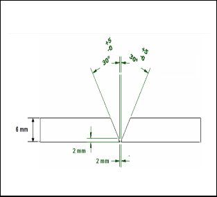
At the present work; single V-groove joint design was used to conduct this welding process as shown in Fig 1. Before weld- ing; all the sharp edges were thoroughly gauged mechanically and cleaned chemically in order to avoid any source of con- tamination like rust, scale, dust, oil, moisture etc. After align- ment the plates together, the first weld pass was deposited using GTAW process, prior the deposition of the second pass; an interpass temperature of around 150o C was conducted. No preheat or post heat treatment was given to the specimens. During this work twelve samples are welded using different current and travel speeds and shielding gases as shown in Table 3.
The specimens for tensile testing, microstr-
ucture studies were conducted from the weld pads as sche-
matically illustrated in Fig 2.
IJSER © 2015 http://www.ijser.org
International Journal of Scientific & Engineering Research, Volume 6, Issue 2, February-2015 590
ISSN 2229-5518
TABLE 1
CHEMICAL COMPOSITION OF AUSTENITIC STAINLESS STEEL 304L
C % | M n% | S i % | S % | P % | C r% | N i% | Fe |
0 .03 | 1 .60 | 0. 401 | 0. 002 | 0. 022 | 1 8.04 | 8 .17 | Bal ance |
TABLE 2
THE CHEMICAL COMPOSITION OF FILLER METAL ER 308L
Fig 1 Single V Groove Joint
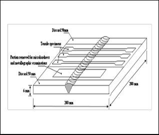
TABLE 3
EXPERIMENTAL CONDITION AND SAMPLES TRACEABILITY
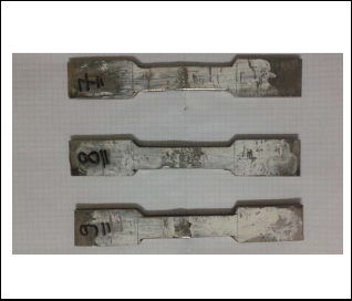
Fig 2 schematic illustration of the specimen sample from the weld pads
Fig 3 tensile test specimens
The tensile test was carried out to determine the ultimate ten- sile strength of the welded joint. The test specimens for tensile were cut from the welded test piece prepen-diculary (trans- verse specimens) to the welding direction as shown in Fig 3.
Microhardness measurements were taken in two directions firstly in the transverse direction perpendicular to the base plate surface and secondly, in the longitudinal direction paral- lel to the base plate surface.Microhardness of different zones of the weldments was measured using Vickers’s micro hard- ness testing machine. The areas of the samples covered by the hardness test positions are shown in Table 4.
IJSER © 2015 http://www.ijser.org
International Journal of Scientific & Engineering Research, Volume 6, Issue 2, February-2015 591
ISSN 2229-5518
Ferrite Number (FN) of weld metal for each test piece was WM
measured using Fischer FeritScope instrument to determine
delta ferrite content of each weld metal.
In order to investigate the microstructure evolution that take place during welding, the test specimen was cut for cross sec- tions, and grind with abrasive paper to a 1200 grit size. A pol- ishing machine was then used to polish the samples to a mir- ror finish before etching. After polishing process, the sample was then electrolytically etched using 10% oxalic acid etching solution and 90% distilled water.A power supply applied ap- proximately 1 Amp and 5 Volts for about 50 seconds to each
0-100 µm
sample. Standard polishing procedures were used for general microstructure observations [7]. Microstructures of different zones of interest like weld metal, HAZ and fusion boundary under different welding parameters were viewed and cap- tured with an optical microscope coupled with an image ana- lyzing software.
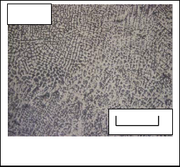
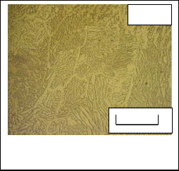
Optical micrographs showing the micros-tructures of weld
zone, fusion boundary interphase and HAZ for different weld-
ing parameters are illustrated from Fig 4 to Fig 11. From mi-
crographs, it is obvious that the structure of the weld metal is
completely different from that of the base metal, all deposited
weld metal have ferrite and austenite phases but for the base
metal it is fully austenitic [8].
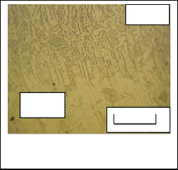
It is observed from these optical micrographs that as cur-
rent increases the heat input increases the dendrite size and
inter-dendritic spacing in the weld metal also increase. This
dendrite size variation can be attributed to the fact that at low
heat input, cooling rate is relatively higher due to which allow lesser time for the dendrites to grow as shown in Fig 4 use 90A and Fig 6 use 130 A [2].
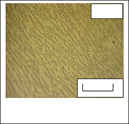
The microstructures of type 304L stainless steel welds when added 2% nitrogen to Argon are shown in Fig 8 to Fig 11. It can be clearly seen that the retained delta ferrite content in the weld metal decreased with nitrogen addition to the shielding gas as mentioned in Table 6 [1, 3, and 4].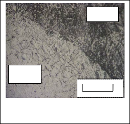
Fig 4 Microstructure of weld metal of S1
WM
HAZ
0-100 µm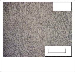
Fig 5 Microstructure of HAZ and fusion boundary of S1
WM
0-100 µm
Fig 6 Microstructure of weld metal of S 3
IJSER © 2015 http://www.ijser.org
International Journal of Scientific & Engineering Research, Volume 6, Issue 2, February-2015 592
ISSN 2229-5518
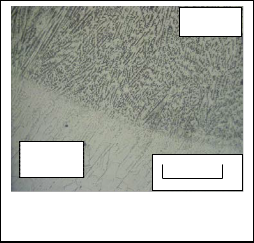
WM WM
HAZ
0-100 µm
0-100 µm
Fig 7 Microstructure of HAZ and fusion boundary of S 3
Fig 10 Microstructure of weld metal of S 12
WM WM
0-100 µm
HAZ
0-100 µm
Fig 8 Microstructure of weld metal of S 9
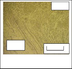
Fig 11 Microstructure of HAZ and fusion bounda- ry of S12
HAZ
WM
0-100 µm
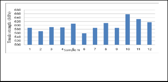
The results for the transverse tensile test are compared in Fig
12. It appears that the ultimate tensile strength of welded joint
of all welds using all studied shielding gases, current and
travel speed exceeded the corresponding specified minimum
value for the AISI 304L austenitic stainless steel base metal,
(485MPa),It is appears that the ultimate tensile of welded
joints which using Argon 98% and 2% Nitrogen higher than
welded joints welded by pure argon due to the nitrogen has
the effect of increasing ultimate tensile strength [1].it is ob- served sample 10 which used welding parameter 90A,
100mm/min travel speed and 98%Argon and 2% nitrogen
Fig 9 Microstructure of HAZ and fusion boundary of S9
revealed the highest value of ultimate tensile strength 658
MPa due to using higher travel speed has short solidification
time, using nitrogen which increase ultimate tensile strength
[9] and using low current which due to low heat input that
increase cooling rate.
IJSER © 2015 http://www.ijser.org
International Journal of Scientific & Engineering Research, Volume 6, Issue 2, February-2015 593
ISSN 2229-5518
The results of the hardness tests revealed varying patterns based on the shielding gas composition, current and travel speed. the hardness values for weld samples 7 to 12 using 98
% argon and 2% N were observed to be lower than weld sam- ples using pure argon due to higher thermal conductivity of the shielding gas mixture due to addition of nitrogen with argon which has higher thermal conductivity increasing heat input that reduces the cooling rate of weld metal consequently hardness values was reduced as shown in Table 5 and Fig 13 show location of hardness test [8].
Furthermore it is observed that the hardness values of the
weld metal decreased with increasing the current due to in-
crease heat input that reduces the cooling rate of weld metal,
consequently hardness values was reduced as shown in Table
5.
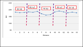
Furthermore, it is observed that the average hardness values
of the weld metal of S 9 using current 130 A and travel speed
50 mm/ min and 98 % argon and 2% nitrogen was the lowest
value due to using high current and low travel speed and us-
ing nitrogen all of this increase heat input that reduces the
cooling rate of weld metal, consequently hardness values was
reduced as shown in Fig 14.
![]()
The ferrite number of each weld metal was measured and the results are shown in table 6. The result of the ferrite number revealed reduction in measured ferrite number can be seen in weld metals as the nitrogen gas added to the shielding gas. Since nitrogen dissolves interstitially in austenite and is a strong austenite stabilizer, the addition of very small amounts of nitrogen to the argon shielding gas during welding will dramatically decrease amount of delta ferrite content in an austenitic stainless steel weld metal [1,10].
TABLE 4
Areas covered by hardness positions
TABLE 5![]()
hardness measurements for welded samples
Test points | |||||
Sample Area | 1,2,3 | 4,5,6 | 7,8,9 | 10,11,12 | 13,14,15 |
Sample Area | Base metal | HAZ | Weld metal | HAZ | Base Metal |
Fig 12 Average values of ultimate tensile strength of
samples.
IJSER © 2015 http://www.ijser.org
International Journal of Scientific & Engineering Research, Volume 6, Issue 2, February-2015 594
ISSN 2229-5518
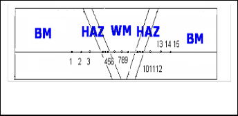
Fig 13 Location of hardness test
.
Fig14 hardness values of S 9
TABLE 6
Table 6 FN of weld metal
The following conclusions can be drawn from the present work:-
• Good joint strength is exhibited by all the joints which show that for welding 6 mm thick AISI 304L SS.
• the ultimate tensile strength of welded joints which using Argon 98% and 2% Nitrogen were higher than welded joints welded by pure argon.
• The dendrite size and inter-dendritic spacing in fu- sion zone is smaller when using low current by in- crease the current the dendrite size and inter spacing increase.
• Delta ferrite content in the weld metal decreased with nitrogen addition to the shielding gas.
• It is observed sample 10 which used welding parame- ter 90A, 100mm/min travel speed and 98%Argon and
2% nitrogen revealed the highest value of ultimate
tensile strength 658 MPa due to using higher travel speed has short solidification time and using nitrogen which increase ultimate tensile strength.
• the hardness values for samples which using 98 % ar- gon and 2% N were observed to be lower than weld samples using pure argon due to higher thermal con- ductivity of the shielding gas mixture due to addition of nitrogen with argon which has higher thermal conductivity increase- ing heat input that reduces the cooli- ng rate of weld metal, consequently hardness values was reduced.
• it is observed that the average hardness values of the weld metal of S 9 using current 130 A and travel speed 50 mm/ min and 98 % argon and 2% nitrogen was the lowest value due to using high current and low travel speed and using nitrogen all of this in- crease heat input that reduces the cooling rate of weld metal, consequently hardness values was reduced.
[1] K. H. Tseng and C. P. Chou "Effect of nitrogen addition to shielding gas on residualstress of stainless steel weldments" Science and Technology of Welding and Joining 2001Vol. 7
No. 1 , 57-62
[2] Subodh Kumar, A.S. Shahi "Effect of heat input on the microstructure and mechanical properties of gas tungsten arc welded AISI 304 stainless steel joints", Materials and Design 32 (2011) 3617–3623
[3] W.A.Baeslack, W.F.Savage and D.J.Duquette "Effect of Nitro-
IJSER © 2015 http://www.ijser.org
International Journal of Scientific & Engineering Research, Volume 6, Issue 2, February-2015 595
ISSN 2229-5518
gen on the Microstructure and Stress Corrosion Cracking of
Stainless Steel Weld Metals" Welding Research Supplement,
1979, 83-90.
[4] R. K. Okagawa, R.D.Dixon, and D.L .Olson "The Influence of Nitrogen from Welding on Stainless Steel Weld Metal Micro- structures", Welding Research Supplement, 1983, 204-209.
[5] ASME Section II, Part A, SA 240, "Specification for Heat – Resisting Chromium and Chromium-Nickel Stainless Steel Plate, Sheet, and Strip for Pressure Vessels", Edition (2010).
[6] ASME Section II, Part C, SFA 5.9, "ASME Specification for Bare Stainless Steel Welding Electrodes and Rods", Edition (2010).
[7] ASTM designation E407-99. "Standard practices for microetch-
ing metal and alloys" 1999.
[8] Usama M A, HosamEldin "Effect of Welding Parameters on the Properties of Austenitic Stainless Steel Weldment", M.SC thesis mech. Design. prod. Eng (Zagazig University), 2009.
[9] S. Nansaarng and C. Chaisang "Influence of Parameters of Gas Metal Arc Welding on Macrostructures and Mechanical Proper- ties of Austenitic Stainless Steels" 6th WSEAS International Conference on SYSTEM SCIENCE and SIMULATION in EN- GINEERING, Venice, Italy, 2007, Nov 21-23, 144-152.
[10] Y. C. Lin, P. Y. Chen "Effect of nitrogen content and retained
ferrite on the residual stress in austenitic stainless steel weld- ments" Materials science and engineering A307 (2001) , 165-
171.
IJSER © 2015 http://www.ijser.org