International Journal of Scientific & Engineering Research, Volume 4, Issue 9, September-2013 28
ISSN 2229-5518
Effect of slip condition on couple stress fluid flow through porous medium with stenosis
Gurju Awgichew, G. Radhakrishnamacharya
resistance to flow and the wall shear stress have been considered.
—————————— ——————————
he atherosclerosis or stenosis is a well-known arterial dis- ease. It involves deposits of fatty substances in the internal lining of an artery. The development of an obstruction in the artery can lead to serious circulatory disorders. In this situa- tion the flow behaviour is quite different from that in a normal artery. The investigations of blood flow through arteries are of considerable importance in many cardiovascular diseases. Hence, the mathematical modeling of this type of flow can be very useful. The actual reason for formation of stenosis is not known but many researchers have studied its effect on the flow characteristics. Mates et al. [1] provided a detailed under- standing of fluid mechanical behaviour of an isolated stenotic lesion in the coronary circulation. Many authors (Young [2], Zendehbudi and Moayeri [3], Radhakrishnamacharya and Srinavasa Rao [4]) studied the flow characteristics by assum- ing blood as Newtonian fluid. But blood shows a non- Newtonian behaviour at low shear rates in tubes of smaller diameters (Whitmore [5], Forrestor and Young [6], Shukla et
al.[7] and Misra and Shit [8]).
The non-Newtonian behaviour of blood is mainly due to the suspension of red blood cells in the plasma. When neutrally buoyant corpuscles are contained in a fluid and there exists a velocity gradient due to shearing stress, corpuscles have rota- tory motion. Furthermore, it is observed that corpuscles have spin angular momentum, in addition to orbital angular mo- mentum. As a result, the symmetry of stress tensor is lost in the fluid motion that is subjected to spin angular momentum. The fluid that has neutrally buoyant corpuscles, when ob- served macroscopically, exhibits non-Newtonian behaviour, and its constitutive equation is expressed by Stokes [9]. This represents the simplest generalization of the classical viscous
———————————————
• Corresponding Author:- G.Radhakrishnamacharya, Profesor of Mathe matics,National Institute of Technology, Warangal, India. E-mail: grk.nitw@yahoo.com
• Gurju Awgichew, Research Scholar in anonymous Institute and Depart-
fluid theory that sustains couple stresses and the body cou- ples. The important feature of these fluids is that the stress tensor is not symmetric and their accurate flow behaviour cannot be predicted by the classical Newtonian theory. The main effect of couple stresses will be to introduce a size de- pendent effect that is not present in the classical viscous theo- ries. The importance of consideration of couple stress effects in studies of physiological and some other fluids was indicated by Cowin [10]. Studies on the couple stress fluid behaviour are very useful, because such studies bear the potential to better explain the behaviour of rheologically complex fluids, such as liquid crystals, polymeric suspensions that have long-chain molecules, lubrication as well as human/sub-human blood (Stokes [9]). Sankad and Radhakrishnamacharya [11] and Srinivasacharya and Srikanth [12] studied the flow of a couple stress fluid with different conditions.
Flows through porous medium occur in filtration of fluids and seepage of water in river beds. Movement of under- ground water and oils are important examples of flows through porous medium. An oil reservoir mostly contains sed- imentary formation such as limestone and sandstone in which oil is entrapped. Modeling of flow problems through porous media has been of great practical significance primarily be- cause of its potential applications in engineering, technology and industry. Porous materials are used in various engineer- ing devices such as catalytic converters and fuel cells due to their advantages in dispersion and chemical reaction by their large contact areas. The flow of non-Newtonian fluids through a porous medium under different conditions was studied by Tong and Hu [13]. Flows through porous media may be rele- vant in many physiological situations such as the flow of blood in the microvessels of the lungs, which may be treated as a channel bounded by two thin porous layers ( Misra and Ghosh [14]).
In the present study, the effect of slip boundary condition
ment, E-mail: gurjua@yahoo.com
IJSER © 2013 http://www.ijser.org
International Journal of Scientific & Engineering Research, Volume 4, Issue 9, September-2013 29
ISSN 2229-5518
on an incompressible couple stress fluid flow through a two dimensional uniform channel with local stenosis and filled![]()
![]()
∂u + ∂v = 0
with porous material, is considered. Assuming that the steno- sis is mild, closed-form solution has been obtained and ex- pressions for resistance to flow and shear stress at the wall have been derived. The effects of various relevant parameters on these flow variables have been studied.
∂x
![]()
− ∂p
∂x
∂y
∂ 2u
![]()
+ µ
∂y 2
−η ′
∂ 4u
![]()
∂y 4
![]()
− µ u = 0
κ 0
(2)
(3)
![]()
− ∂ p = 0
∂ y
(4)
We consider steady, incompressible couple stress fluid flow
where u and v are the velocity components along the x
through a two dimensional uniform channel with local steno-
and y directions respectively, p is the pressure, κ 0
is the
sis. It is assumed that the channel is filled with porous materi-
al. Cartesian coordinate system is chosen so that the x-axis
coincides with the center line of the channel and the y-axis
normal to it. The stenosis is supposed to be mild and develops
in a symmetric manner. The boundary of the channel is taken
as (Shukla et al. [7] )
permeability constant of the medium, µ is the coefficient vis- cosity of classical fluid dynamics, η ′ is the couple stress fluid
viscosity.
The boundary conditions are given by
δ
2π
L0
![]()
− d Da ∂ u u = 0
α1 ∂ y
at y = ±η
(5)![]()
η ( x) = d0 − 2 1 + Cos L
![]()
( x − d1 − )
2
; d1 ≤ x ≤ d1 + L0
(1)
0
d0
; otherwise
∂ 2 u
![]()
= 0
∂ y 2
at y = ±η
(6)
where d 0 is the mean half width of the non-stenotic region of the channel, L is the length of the channel, L0 is the length of stenosis and δ is the maximum height of stenosis.(Fig.1.)
Here (5) is the Saffman’s slip boundary condition (Bahtt and Sacheti [16]) and (6) indicates the vanishing of couple stress. Further, Da is the permeability parameter (or Darcy number)
and α1 is the slip parameter.
Taking the restriction for mild stenosis (Young [2]) and solv- ing (2)-(4) under the boundary conditions (5) and (6), the ve- locity is given as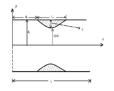
![]()
u( y) = − κ 0 ∂ p [R* cosh(m* y) − R* cosh(m* y) + 1]
(7)
where
µ ∂ x 2 1 1 2
m* =
µ
1 +
1 − 4η ′
µ 4η ′

1 2η ′
, m* =
0
1 −
2η ′
1 −
µ κ 0
Fig.(1) Geometry of the channel with local stenosis![]()
R* = (m 1 )

cosh(m*η )
(m * ) 2
![]()
R * = 2
cosh(m*η )
1 b* − b* , 2
b * − b*
1 2 1 2
The equations governing the motion of an incompressible![]()
couple stress fluid flow for the present problem, by neglecting
body forces and body couples, are given as (Alemayehu and![]()
b* = (m* ) 2 cosh(m*η ) cosh(m*η ) + d 0
Da
m* sinh(m*η )
Radhakrishnamacharya [15] )
1 1 1 2 2
1
IJSER © 2013 http://www.ijser.org
International Journal of Scientific & Engineering Research, Volume 4, Issue 9, September-2013 30
ISSN 2229-5518
![]()
d
b* = (m* ) 2 cosh(m*η ) cosh(m*η ) + 0
Da
m* sinh(m*η )
= * 2 =
2 cosh(
)cosh(
![]()
) + Da
sinh( )
2 2 2 1
1 1
1
b1 b1 d 0 m1
m1 H
m2 H m2
1
m2 H
The flux Q of the fluid is given by
b = b* d 2
= m2
cosh(m2 H )cosh(m1 H ) +
![]()
Da
m1 sinh(m1 H )
α1
η
Q = 2 ∫ udy
0
From eq.(10) we obtain
∂ p = =− Q 1
− 2 κ
∂ p
sinh(m*η )
sinh(m*η )
![]()
∂ x 2
sinh(m1 H )
sinh(m2 H )
(11)
= 0 R* 1 − R* 2 +η
(8)
R2
− R1
+ H
µ ∂ x 2 * 1 *
1 2

m1

m2
Introducing the following dimensionless quantities
Integrating eq.(11) with respect to x , we get pressure differ- ence ∆p along the total length of a channel as
* δ
* x d *
d
1 L *
L
0 ,
![]()
δ = , x d0
= L , 1 = L ,
0 = L
p =Q 1 1
![]()
H = η
, p* =
![]()
![]()
p , Q* = Q
(9)
∆ = 2 ∫
R

sinh(m1 H ) − R

sinh(m2 H )
dx
+ H
(12)
d0 =µUL
Ud0
m1 m2
κ
0
The resistance to flow, denoted by λ , is defined by
in eq.(1) and eq.(9) , we get ( after dropping asterisks)![]()
λ = ∆p
(13)
∂ p
![]()
Q = −2 R2
∂ x
sinh(m1 H )
![]()
m1
− R1
sinh(m2 H )
![]()
m2
+ H
(10)
Q
Using eq. (12) in eq. (13), we get
=1 1 1
where
m(= d0 m
1
![]()
= d0 (µ /η ′) 2 ) is a couple stress parameter,
λ = 2 ∫
R2
sinh(m1 H )

m1
− R1
sinh(m2 H )

m2
dx
+ H
(14)
κ
![]()
Da = 0
, m = m* d =
m 2
1 + 1 −
The pressure drop in the case of no stenosis (H=1), denoted

d 0 1 1 0 2
m 2 4
m 2 Da ,
by ∆pn , is obtained from eq. (12) as
m = m* d =
1 −
2
−
m 2 Da ,
p =Q 1 1
![]()
R = m 1
2
cosh(m1 H )
2
, R = m 2 cosh(m2 H )
∆ n =
2
∫
R22

sinh(m1 )
m1
− R11

sinh(m2 )
m2
dx
+ 1
(15)
b1 − b2
![]()
b1 − b2
IJSER © 2013 http://www.ijser.org
International Journal of Scientific & Engineering Research, Volume 4, Issue 9, September-2013 31
ISSN 2229-5518
where
The shear stress at the wall in the absence of stenosis (H=1),
denoted by (τ w ) n , can be obtained from eq. (21) as
2 2
R = m 1
cosh(m1 ) ,
m 2 cosh(m2 ) ,
( ) = =− Q R22 m1 sinh(m1 ) − R11 m2 sinh(m2 )
![]()
b11 − b22
R22 =
![]()
b11 − b22
![]()
τ w n
2
22
sinh(m1 )

11

sinh(m2 ) + 1
(22)![]()
2 Da
m1
m2
b11 = m1
cosh(m1 ) cosh(m2 ) + α
m2 sinh(m2 ) ,
![]()
The normalized shear stress at the wall,τ w,, , is given by
1
![]()
τ = τ w
![]()
2 Da
w (τ
w )n
![]()
(23)
b22 = m2
cosh(m2 ) cosh(m1 ) +
α1
m1 sinh(m1 ) .
The resistance to flow and the wall shear stress are the two important characteristics in the study of blood flow through a
The resistance to flow in the absence of stenosis, λn , is defined
by
stenosed artery. The expressions for resistance to the flow and wall shear stress, given by eq.(18) and eq.(23) respectively![]()
λ = ∆pn n Q
Using eq. (15) in eq. (16), we obtain
(16)
have been numerically evaluated using MATHEMATICA software for different values of relevant parameters and pre- sented graphically.
Figures (2)-(5) show the effects of various parameters on the resistance to flow in a uniform channel with mild stenosis . It can be observed that the resistance to flow increases with the height of stenosis (Figures 2-5). This result agrees with the
λ =1 1 1
dx
(17)
previous results obtained by Young [2], Shukla et al. [7], Cha-
n = ∫
2 0
R22

sinh(m1 ) −
m1
R11

sinh(m2 )
m2
+ 1
turani and Samy [17]. Further, it can be noticed that the re- sistance to flow increases with the slip parameter and the length of stenosis (Figures (2) and (3)) and with Darcy number (Figure 4) but decreases with couple stress parameter (Figure![]()
The normalized resistance to the flow, λ , is given by
5).
Figures (6)-(8) show the effects of various parameters on the wall shear stress. The wall shear stress increases with the![]()
![]()
λ = λ
λn
(18)
height of stenosis (Figures 6-8). This result agrees with previ- ous results obtained by Young [2], Lee and Fung [18], Shukla
The shear stress acting on the wall of the channel is given by
et al. [7]. Moreover, the wall shear stress increases with slip
parameter (Figure 6) but decrease with Darcy number (Figure![]()
τ = −µ ∂u
w ∂y
y =η
(19)
7) and the couple stress parameter (Figure 8). However, the decrease of the couple stress parameter is not very significant (Figure 8).
Introducing the dimensionless quantity
τ * =
![]()
τ w
µU
![]()
d0
(20)
and using eq.(15) in eq.(19), we get(after dropping asterisks)
= =− Q R2 m1 sinh(m1 H ) − R1 m2 sinh(m2 H
![]()
τ w 2
R2
sinh(m1 H )

m1
− R1
sinh(m2 H )

m2
+ H
(21)
IJSER © 2013 http://www.ijser.org
International Journal of Scientific & Engineering Research, Volume 4, Issue 9, September-2013 32
ISSN 2229-5518
![]()
![]()
Figure(2) Effect α1 on λ
(d1 = 0.4, L0 = 0.2, Da = 0.003, m = 0.2)
Figure(5) Effect of m on
λ (d1 = 0.4, L0 = 0.2, Da = 0.003,α1 = 0.02)
![]()
Figure(6)Effect of
![]()
Figure(3). Effect α1 on λ
(d1 = 0.4, L0 = 0.3, Da = 0.003, m = 0.2)

α1 on τ w
(d1
= 0.4, L0
= 0.2, x = 0.5, m = 0.2, Da = 0.003)
![]()
Figure(4)Effect of Da
on λ (d1 = 0.4, L0 = 0.2,α1 = 0.02, m = 0.2)
![]()
Da on τ w
Figure 7. Effect of
(d1 = 0.4, L0 = 0.2, x = 0.5, m = 0.2, α1 = 0.02)
Figure(8) Effect of
IJSER © 2013 http://www.ijser.org
International Journal of Scientific & Engineering Research, Volume 4, Issue 9, September-2013 33
ISSN 2229-5518
![]()
m on τ w
(d1 = 0.4, L0 = 0.2, x = 0.5, α1 = 0.02, Da = 0.003)
vol. 122, pp. 137-153, 1997.
[15] H. Alemayehu and G. Radhakrishnamacharya, “Dispersion of a so- lute in peristaltic motion of a couple stress fluid in the presence of
The flow of steady and an incompressible couple stress fluid through a porous medium with local stenosis has been pre- sented. Solutions have been obtained for mild stenosis and using slip condition. It is obtained that both the resistance to
flow and shear stress increase with height of stenosis δ , and
magnetic field,” International Journal of Engineering and Applied Scienc- es, vol. 7, pp. 155-160, 2011.
[16] B. S. Bhatt and N. C. Sacheti, “On the analogy in slip flows,” Indian
Journal of Pure and Applied Mathematics, vol. 10, pp. 303-306, 1979.
[17] P. Chaturani and R. P. Samy, “Blood flow through stenosed arteries,”
slip parameter
α1 but decrease with couple stress parameter
Proc. of First Int. Conf. of Physio. Fluid dynamics, Madras, India, pp. 63-
m . Moreover, the resistance to flow increases with Darcy number Da. However, the wall shear stress decreases with
Darcy number Da.
[1] R. E. Mates, R. L. Gupta, A. C. Bell and F. J. Klocke, “ Fluid dynamics of coronary artery stenosis,” Circ. Res., vol. 42, pp. 152-162, 1978.
[2] D. F. Young, “ Effects of a time-dependent stenosis on flow through a tube,” J. Eng. Ind. Trans. ASME., vol. 90, pp. 248-254, 1968.
[3] G. R. Zendehbudi and M. S. Moayeri, “Comparison of physiological and simple plusatile flows through stenosed arteries,” J. Biomech., vol. 32, pp. 959-965, 1999.
[4] G. Radhakrshnamacharya and P. Srinivasa Rao, “Flow of a magnetic fluid through a non-uniform wavy tube,” Proc. Nat. Acad. Sci. India, vol. 76, 241-245, 2007
[5] R. L. Whitmore, “ Rheology of the Circulation,” Pergamon Press, New
York, 1968.
[6] J. H. Forrester and D. F. Young, “Flow through a converging- diverging tube and its implications in occlusive vascular disease,” J. Biomech., vol. 3, pp. 307-316, 1970.
[7] J. B. Shukla, R.S. Parihar and B. R. P. Rao, “Effects of stenosis on non-Newtonian flow of the blood in an artery,” Bull. Math. Biol., vol.
42, pp. 283-294, 1980.
[8] J. C. Misra and G. C. Shit, “Blood flow through arteries in a patho- logical state: A theoretical Study,” Int. J. Engng. Sci., vol. 44, pp. 662-
671, 2006.
[9] V. K. Stokes, “Couple stresses in fluids,” Phys. Fluids, vol. 9, pp. 1709-
1715, 1966.
[10] S. C. Cowin, “The theory of polar fluids, Advances in Applied Me- chanics,” Editor: C.S. Yih, 14, Academic Press, New York, pp. 279-347,
1974.
[11] G. C. Sankad and G. Radhakrishnamacharya, “Effect of Magnetic field on the peristaltic transport of couple stress fluid in a channel with wall properties,” Int. J. Biomath., vol. 4, pp. 365-378, 2011.
[12] D. Srinivasacharya and D. Srikanth, “Effect of couple stresses on the pulsatile flow through a constricted annulus,” Comptes Rendus Meca- nique, vol. 336, pp. 820-827, 2008.
[13] D. Tong and H. Hu, “Flow analysis of non-Newtonian viscoelastic fluids in porous media,” J. Porous Media, vol. 13, pp. 477-486, 2010.
67, 1985.
[18] J. S. Lee and Y. C. Fung, “Flow in locally constricted tubes at low
Reynolds numbers,” J. Appl. Mech. Trans. ASME., vol. 37, pp. 9-16.
1970.
[14] J. C. Misra and S. K. Ghosh, “A mathematical model for the study of blood flow through a channel with permeable walls,” Acta Mechanica,
IJSER © 2013 http://www.ijser.org