International Journal of Scientific & Engineering Research, Volume 2, Issue 12, December-2011 1
ISSN 2229-5518
Effect of friction stir welding pressure on the microstructure and mechanical properties of weld joints
Nofel M.AL-Araji, Karrer M.Kadum, Akeel A. AL-Dayni
Abstract— The (FSW) of commercial aluminum were studied. The Vickers microstructure of the tested spacemen’s ranged from (33-48) VHN. The mechanical properties were investigated and the result shows that they are dependents on the weld test parameters su ch as spacemen thickness weld speed and weld pressure. The microstructure, including grain and sup grain structure, of has metals were compared with the weld zone and heat effected zone using transition electron microscopy. The microstructure of weld zone was characterized by dynamic recrastallization producing fine grain structure. However ,the heat affected zone exhibited an inhalation of the dislocations due to the increase the welding pressure at the welded joints which lead to formation of porous ,cavities and uneven deformed layers.
—————————— ——————————
riction-stir welding (FSW) in an new joining method drived from convetional friction welding which enables the advantages of sold ,state welding. This joining tech-
nique has been shown to be viable for joining aluminum alloys
,copper ,magnesium and ether low-melting point materials [1].
Friction stir welding is relatively simple process [2]; a specially
shaped cylinderacal toll with a profiled probe ,made from a
hard and wear resistance materials relative to the material being welded ,is rotated and plunged in to the abutting edges
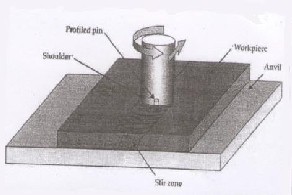
of the part to be joined as in Fig.1. After entry of the profiled probe to almost the thickness of the material and to allow the Tool shoulder to just penetrate in to the plate, the rotating tool is transitioned along the joint line. The rotating tool develop frictional heating of the material, causing it to plasticized and flow from the front of the tool to the bag where it cools and consolidates to produce a high integrity weld, in the sold face.
In the FSW processes, heat is generated by friction between the tool and the workpiece. This heat flows in to the workpiece as will as the tool. The amount of heat conducted in to the workpiece determines quality of the well, residual stress and distortion of the workpiece. The amount of the heat that flows to the tool dictates the life of the tool and the capability pof the tool for the joining process. The majority of the heat generated from the fraction, i.e. about 95% is the transferred into the workpiece and only 5% flows in to the tool and the friction of the rate of plastic work dissipated as heat is about many [3]. There is numerous applications in the maritime and automo- tire industries for this technique. Friction stir welding, a deriv- ative of the more conventional friction welding process , as
made it possible to join difficult to weld aluminum alloys without cracking, porosity, or distortion. The process does not require filler materials, shielding gas, edge profiling and oxide removal. The joint faces do not have to be in intimate contact and the configurations may include square butt, combined butt lap and multiple lap joint [4] . The weld quality can be determined to some extent by the stir welding tool profile, the tool rotation and welding speed. The ability to join dissimilar alloys which are made through dissimilar processes, such as casting extrusions and rolling using friction stir welding, has been demonstrated elsewhere [5],[6]. The objectives of this paper where to compare the microstructures associated with friction, stir welding of commercial aluminum. Through thickness micro hardness profiles where also studied for com- parison. In addition, the effect of weld parameters on the mi- crostructures and mechanical properties and evaluated.
————————————————
Nofel M.AL-Araji is with Department of Production Engineering and
Metallurgy, University of technology, Baghdad, Iraq
Karrer M. Kadum is director of Ministry of Science and Technology, Kar-
bala, Iraq
Akeel A. AL-Dayni is with Department of mechanical, Najaf Technical
Institute, Najaf, Iraq
Schematic of the friction stir welding processes
Fig.1
IJSER © 2011
International Journal of Scientific & Engineering Research, Volume 2, Issue 12, December-2011 2
ISSN 2229-5518
The materials tested are hot, rolled plates of commercials aluminum 1100 (wt% cu:- 0.15 mg> 0.05, mn 0.05, Fe 0.5, si
0.05 and AL. Bal). a number of rectangular work pieces of 100 mm width, 200 mm length, and 6 mm thickness where ma- chined out of the plates and submitted for Fsw.
Fsw was carried out according to the following sequence. Appear of work pieces free from oil films where abutted along longitudinal section and fastened rigidly on the steel backing plate, which was mechanically fixed on the bed of a vertical type-milling machine, Fig.1. A specially designed rotating tool of standard carbon steel screw of 0.06 cm in diameter which was inserted in to a milling chuck. During welding this mil- ling chuck was forced against the upper work piece surface with sufficient pressure and the remove up to 0.5 mm of ma- terial under shoulder. The feature expanded the (FSW) zone near the top surface as shown in Fig.2.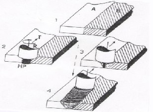
Fig.2. The feature expanded the (FSW) zone near the top surface
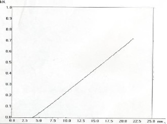
Fig.3. Calibration curve
The welding pressure calculated by using the low (P=F/A),
where P= welding pressure, F= force and A= c.s area of the welding tool.
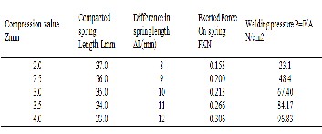
The friction-stir welded work piece were than cat through section, polished and etched for metallographic observations of weld zone microstructure, using electron microscopy. Vick- ers micro hardness were examined across the weld zone, ex- tending into the two butted base metals near the weld thick- ness mid-section and at other graduated thickness propor- tions. The welding pressure calculated by using a steel spring of 45 mm length table (1 and 2), this spring compacted to dif- ferent length utilizing tensile testing machine at different forces, then a calibration curve plotted between force (KN) and spring length as shown in Fig.3.
TABLE 1
WELDING PRESSURE CALCULATION
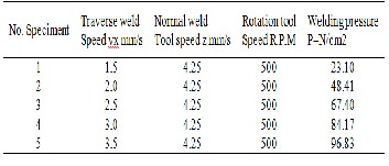
TABLE 2
WELDING PRESSURE CALCULATION
From Fig.1 illustrates the friction-stir welding of the commer- cial aluminum alloy. A Vickers micro hardness testing testing machine Buehler Digital microhardness Tester MMT-3 was used to measure the hardness across the weld cross section of the (FSW) joints; the measured values are obtained and dia- gram drawn in Fig.4. The base metal showed average hard- ness value of (35HV), But the as –welded joint the hardness was (45 HV). The weld zone is considerably harder than the base metal. All hardness profiles for all specimens shows a difference values of hardness between the base metals and the FSW zone increased due to a super plastic flow accommodates the FSW process.
IJSER © 2011
International Journal of Scientific & Engineering Research, Volume 2, Issue 12, December-2011 3
ISSN 2229-5518
This mechanism is recognized as a universals external super plastic deformation-flow mechanism [7]. also we can see in all tested specimens that the hardness values increases from the FSW zone toward the base metal, and the heat effected zone increases as welding pressure increased, this shows the effect of heat generation at the FSW zone due to the friction take place between tool and weld metal. A locally melting of metal take place at the weld zone, this can be recognized from SEM micrographs which shown a remarkable dimple and laminal structures observed on the c.s area of FSW zone.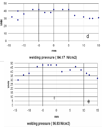
Fig.4. Microhardness profile for (FSW) C.S area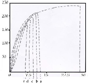
Fig.5. Normal strain, En (%) (welding pressure (N/cm2)
a=23.1, b= 48.4, c=67.4, d=84.1 ,e=96.8 ,f= base matel)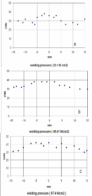
Fig.5 shows nominal tensile stress –nominal strain curves of FSW zone compared to heat of the base metal. Both yield stress and ultimate tensile strength of the FSW zone where at a lower level as that for the base metal. This difference in hard- ness is due to the work hardening that take place in the FSW
IJSER © 2011
International Journal of Scientific & Engineering Research, Volume 2, Issue 12, December-2011 4
ISSN 2229-5518
zone and the materials seemed to be more brittleness than base metal. The elongation in all tested specimens decreases as the weld pressure increased, so at higher welding pressure of (96.8 n/cm2). The elongation is about 7.0% and at lower weld- ing pressure (23.1n/cm2), the elongation is about 12.5%. this indicated that the ductility of FSW zone effected by the heat generation at the FSW zone welding effect the microstructure of the materials so the effected zones have been investigated.
a) Welding pressure (23.1 N/cm2)
b) welding pressure (48.4 N/cm2)
c) Welding pressure (67.4 N/cm2) d) Welding pressure (84.17 N/cm2) e) Welding pressure (96.8 N/cm2)
Fig.6. SEM micrographs showing weld zone c.s area
IJSER © 2011
International Journal of Scientific & Engineering Research, Volume 2, Issue 12, December-2011 5
ISSN 2229-5518
The SEM microstructure of welded materials are shown in Fig.6. The weld zone are clearly visible under different weld- ing pressure, because of the different contrasts develop after etching the futures of weld zone porous and laminated layers with plastic flow of materials at the welding direction and this futures increases as welding pressure increased. Differences between the advancing and retreating sides of the weld joints are also apparent, with amore clearly defined edge to the weld on the advancing side as well as and extended section of the weld zone near the material top surfaces, also on the advanc- ing top side, and the structure of weld surface. Studies have show that the rejection in strength friction stir weld is cased by the dissolution, coarsening , local melting and transformation of the strengthening recibitates. Hasim KAFALI,Nuran Ay [8] the increased capacity of plastic deformation as a result would be expected due to the effect of welding pressure.
The friction stir welding joint of commercial aluminum alloy
1100 has a brittle behavior under welding pressure.
1. The ductility of the weld joint decreases as the weld-
ing pressure increases.
2. The elongation percent decreases as welding pressure
increase.
3. Microhardness of weld joint increases as welding
pressure increase.
4. the heat effected zone area increased as the welding
pressure increased.
5. local melting process and plast flow take place at the weld zone.
[1] Tang,W.,Guo, Journal of materials processing and manufacturing science,
7(2),pp.163-172.1998.
[2] E.D,Nicholas,.Pros.of ICAA,6(6thint.Conf.alumunim alloys),Toyohashi,Japan, (139-151,1998).
[3] Yah J.Chano, transactions of the ASME, Vol.125, February. 2003.
[4] C.J.Dawes. Welding Journal, Vol.75, No 3, pp (41-45), 1996. [5] L.E.Murr.Res. Innovations, Vol.7, No.3, pp.(211-223), 1998. [6] Ying Li, L.E., Sci Eng., 1999, in press.
[7] Rodrigues, D.M.et al., Influence of friction stir welding parameters on the
microstructure and mechanical properties of AA 6016-Tu thin welds mate- rials and design, 2008, In press, corrected proof.
[8] Hasim KAFALI; Naran AY ,International conference on Aerospace sciences
and aviation technology. ASAT-139,May 26-28,2009.
IJSER © 2011