International Journal of Scientific & Engineering Research, Volume 4, Issue 12, December-2013 745
ISSN 2229-5518
Effect of cylindricity and roundness on thinned- wall welded tube of low carbon steel.
Mohi Uddin Ahmed, Shayan Hussain
Abstract— The present study deals with the Axis shift distortion of the tubes after welding. Two seamless asymmetrical thinned wall tubes with 1.45mm thickness having an outer diameter of 118 mm were welded together using GTAW process. Using a specially designed welding back-up tool, high quality weld with full penetration was obtained. The results of cylindricity and roundness with and without back- up tool and external alignment fit up was obtained and investigated. The effect of tacking on geometrical tolerences was also included in this study.
Index Terms— Alignment, Backup tool, Cylindricity, Roundness, fixture, GTAW, thinned wall tube.
—————————— ——————————
1 INTRODUCTION
Cylindrical features of any machined components play a key role in high tech industries like aerospace, aeronautical, nuclear and power generation applications. Various efforts are made by the researchers to investigate the geometric al tolerances er-
ror of machined components. However in welding, precision
ment neutral axis, preheat or peening etc.
Rapid cooling by means of heat extractor or heat sinks has
been used succefully in the aircraft industry. By means of hy-
draulic or pneumatic clamps the parts of the weldment are put
in intimate contact with larger masses of highly conductive ma-
terials. These are known as heat sink, which pull the heat away
from the weld quicker than normal. This creates a more uniform
IJSER
controlling and prediction of these features is somehow diffi- cult. Deviation in geometrical tolerances due to weld joining in a cylindrical components is a considerable task and there should be a well proposed margin in the process while welding is involved. Present study deals with the evaluation of cylin- dricity and roundness of the precise machined asymmetrical long tubes after circumferential welding and effect of this axis shift was investigated. According to “G.Ravichandran [1], axis shift distortion is one type of distortion encountered during circumferential welding. The result of this type of distortion is the loss of coaxiality of the pipes. This type of distortion is caused by the time lag in the solidification of various segments of weld metal around the circumference. The development of shrinkage forces in the weld metal especially in axial direction is non uniform due to the time lag, and this causes the axis shift of the pipes.
The arc welding process involved heating. High temperature heat is mainly responsible for such kind of distortion, warpage and stresses. Thin tube are more susceptible for welding distor- tion which tends to deviate coaxiality.Low digression in cylin- dricity and circularity may be obtained by controlling the dis- tortion of the components.The distortion may be controlled pre- liminary by using the restraining fixture and with the proper
————————————————
• Mohi uddin Ahmed M.Engg. (Energy), PH +92 334 7071666. E-mail: khanned@hotmail.com
• Shayan Hussain M Engg. (Manufacturing), PH +92 3463228414.
E-mail: shayanhussain4@gmail.com
joint design. Number of tack welds before welding also has the major role in controlling distortion. The other techniques in- volved back step welding, balanced welding about the weld-
heat distribution and reduces the heat differential and distor-
tion. Some weld fixtures have water cooled heat sinks to help
reduce distortion. “Howard B. Carry [2].
A. Malik [3] in his evaluation revealed that longitudinal dis-
tortion mainly affected by the way you hold down the structure
for circumferential welding. Those jobs that are properly clamped, exhibit low axial shrinkage against those who are low restraints. He also concluded that diametric/radial shrinkage for different clamping conditions showed no significant varia-
tion.
From Ref [4] ~ [12], review of literatures shows the various
fixture designs which were effectively used by the inventors
for circumferential welding. The idea of using internal fit up
tool for thinned cylindrical components is very common and effective which not only holds the components firmly but also keeps them aligned to far extent across the weld line. So those peripheral factors associated with welding distortion might be reduced like overlapping, root gap etc. For smaller diameter internal fit up, “simplicity in design” is very important. But it is rather tricky to achieve because of small dia, as the tube diame- ter decreases the tool’s design becomes difficult to manufacture and operate internally.
In the present study all possible countermeasures were taken
to minimize the external influences (which may lead to deviate geometrical tolerances) for good prediction of the result. It in- cludes the use of internal fit up and external fixture during as- sembly, joint geometry design & root gap, no of tack welds etc. Practical experience shows that the use of complex internal fit up has more inclination to get trapped inside tube assembly after welding. It is due to the thermal expansion caused by the welding heat to the moveable parts of the tool which have lesser tolerances. In present work, tool with single segment is de- signed and used initially. Single segment tool is very simple in
IJSER © 2013 http://www.ijser.org
International Journal of Scientific & Engineering Research, Volume 4, Issue 12, December-2013 746
ISSN 2229-5518
making and good in welding but found very difficult to extract in long tube welding. All test pieces welded using single seg- ment design rejected in the end due to damaging surfaces in tool’s extraction. The tool reshaped afterwards in multiple seg- ments. The welding is carried out successfully with good results again. However in few cases the same problem faced was get- ting it stuck inside when retract the tool after welding. Also the threaded components like expander blocks tend to malfunction due to the thermal expansion. This tool functionally effectual but needs further modifications. Finally, modified collapsible design was proposed by making the components simple having tapered features for guidance rather threaded.
For geometrical features measurements, different studies are
available. At the Kielce University of Technology (PL) a new
method of cylindricity measurements using V-blocks has been
developed Ref [13].All the experiments conducted in this re-
search and their comparative study concluded that V-Blocks
method can effectively be used for measuring the cylindricity of the circular jobs with great accuracy. In Ref [14], Measuring systems and devices frequently used for geometric control of parts both in industrial and in research laboratories were ana- lysed.In the present study, ITP CMM with measuring accuracy of 50 micron was used to measure the cylindricity and round-
ness of all test pieces.
all test pieces. Before welding, all the components were pre- pared for cleaning. Efforts are made to avoid any welding de- fects related to unclean surfaces and joining edges such as po- rosity, gas pores etc.Proper cleaning is made with the use of flap wheel and emery papers and washout in Tricholoro eth- ylene bath for degreasing.
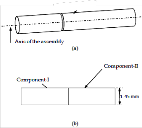
Fig. 1 (a) Seamless tube specimen
IJSE(b) JoiRnt geometry (Square butt-weld groove)
2 Materials and Procedure.
In precise engineering works, the role and use of ultra high strength steels are enormous.15CrMoV6 acc. to AIR 9160/C is the same kind used in the present work because of its high yield strength, excellent weldability and ease of mamachin- nig.The chemical composition of the base metal and filler wire consumed is given in Table 1.
TABLE 1
Chemical Composition (wt. %).
Two asymmetrical seamless tubes of 1.45 mm of thicknesses having length of 300 mm and 500 mm respectively as shown in Figure 1 (a) were used as a test specimen .Total 14 Nos. test pieces were prepared for welding. Full shop floor experi- mental set-up with rotary positioner and manipulator assy along with alignment-fit up with less invasion of human was established for better results. All the specimens were GTAW welded, single pass using modified tool and randomly inves- tigated for qualification thru NDT.
3 Experimental Setup.
3.1 Joint Design
The joint designs for all pipe welding cases have been fairly well standarized.Those pipes whose thicknesses are lesser square butt groove is normally preferred. Figure 1(b) shows the same full- penetration joint used in the present study for
3.2 Joint Alignment and Internal Fit up.
The most important factor in obtaining high quality weld joint for seamless thin wall tubes is to make sure the fit up prior to welding is perfect. Due to the lesser thickness of the test spec- imen “burn through” is the serious issue alonwith incomplete or excess penetration. Such type of defects may be encoun- tered by using internal backup support. To minimize the dis- tortion due to heat input this internal backup tool plays a vital role of a heat sink and have the positive effect on microstruc- ture of the weldment.As stated, the back up support must not be stuck up and should easily be removed after welding. In the present work, considering the excess length of the assem- bled job and possibility in pulling out the tool hardly after welding, the expandable tool was designed into three curved segments that have the outer radius equal to inner radius of the test specimen. The main wedge assembly is made of Mild Steel and integrated together with a holding spring as shown in figure.2
Fig. 2. Internal Fit up Tool with segmented copper sleeves.
IJSER © 2013 http://www.ijser.org
International Journal of Scientific & Engineering Research, Volume 4, Issue 12, December-2013 747
ISSN 2229-5518
These holding springs attain a precise fit to the wedge assem- bly in expansion and provide smooth dislodge when tool col- lapses at the end of welding operation. For proper orientation and guidance of these springs and to avoid any slip during process, two grooves having 10mm width, 80 mm a part are slot in the wedge’s outer surface. Two insulating layers having
2 mm of thickness encapsulate the wedge assembly over these springs. So the chance of transferring heat from the source zone to the internal parts like wedge or sliding blocks is pre- vented. As it was experienced in older design that the whole assembly is impeded in removal phase due to thermal expan- sions. A copper sleeve of thickness 4 mm is incorporated over the insulating layers providing 3600 flipside support to the joining surfaces. This copper sleeve not only eliminates the chance of needless penetration during welding but also pro- vides HAZ support to far extent of the body and therefore reducing the possibility of radial changes.
The whole assembly is directed by two tapered blocks (Rear and Side) which are mounted on a single main shaft. The shaft is end and centrally threaded, provides the centre support up to the entire length of the tube. The shaft is well supported via two fixture plates at the end of the Tube assembly.
The method of expanding the whole assembly is somehow conventional but found very effective and simple during all
welding operations.
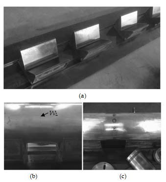
up of Mild steel. A single 600 mm long block of 150 mm by 108 mm cross section was machined and parted off into four small blocks. These V-Blocks are guided on a 2 m long platform pre- cisely machined as shown in Figure 4 (a). This external guidance provides a smooth guided surface for assembly and tacking. The whole system is placed on a surface table. Tacking was done thru “Manual precision Tig 375 Lincoln Electric”. 12 Nos.tacks at 300, starting from the weld start line was carried out. Matching of the abutting surfaces with zero root gaps was ensured during this manual tacking as shown in figure 4(b) and (c).
IJSER
Fig. 3. Internal Fit up Tool assembly
For this purpose, the main shaft is rotated by spanner which tends to move both tapered blocks in opposite direction along the length of the tube. These tapered blocks are constrained against the rotation by a key way which is incorporated in the modified design. These key-ways prevent the relative motion of the blocks with the main body. At full expansion, the inter- nal fitup acquires the internal dia of the tube and provides abutting surfaces a “perfect match”. The copper sleeve is without any groove underneath the weld line so purging is not used during all welding operations. The partial assembly of the pipe is shown in figure 3. After welding the system may be retracted by reversing the stated procedure.
3.3 External Fit up Assembly.
It is obvious that small dia tubes with extended length always difficult to aligned accurately for welding. Root gaps, even 0.2 mm between the joining faces have a tendency to shift the cy- lindricity values from the desired range. Therefore proper alignment of both ends is crucial and should be maintained. Minute lateral displacements must be avoided. Here to over- come this problem, fixture is designed for perfect in-line fit- ment. This fixture is composed of four V-Blocks system made
Fig. 4 (a) V Blocks guided platform assembly for long tube assembly. (b) Joining surfaces with zero root gap
(c) Tacking before welding.
3.4 Welding Setup
The entire assembly alongwith the internal fitup is mounted over the welding positioner through adopter (as shown in fig- ure 5) for circumferential welding. Fully automatic high tech GTAW welding set-up with an advance controller and auto- matic wire feeder was used for the present study. Total 14
Nos. joints were welded with this setup.10 Nos. samples were obtained with all aforementioned fitments and tools for geo- metrical tolerance’s study and labeled as “case-I”. In case-II, 2
Nos.samples were welded without internal backing tool for investigation of the backing effects on weld bead geometry. Rest of two in case-III were obtained without using internal fit up tool and external alignment platform for finding their ef- fects on cylindricity and roundness. Process parameters are shown in Table 2. In all cases, positioner’s RPH was set on 5.
IJSER © 2013 http://www.ijser.org
International Journal of Scientific & Engineering Research, Volume 4, Issue 12, December-2013 748
ISSN 2229-5518
Fig. 5 Welding setup.
Fig. 6. Cylindricity & Circularity measurement using CMM.
During the measurements the specimen is placed on V-Block of the surface table. A ruby sphere of stylus touches the de- fined cross sections along the length of the tube. Three points,
1200 apart at each cross section were taken starting from the both circumferential ends and 50 mm across a weld line of the assembly. Values obtained by the computational program- ming of the machine thru digitally stored data in the software. Each specimen is evaluated for cylindricity twice, at tacking and after welding. All the measurements were carried out by the single operator with temperature controlled atmosphere.
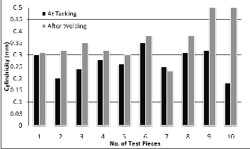
TABLE 2
Process Parameters.
Fig. 7 Cylindricity values in Case - I
Cylindricity values in “case-I” is shown in figure 7.In most
4 Measurement of Cylindricity.
Cylindricity was measured thru ITP CMM with measuring accuracy of 50 micron shown in figure 6.
cases the values after welding increased with slight difference. However the diversity in last two jobs is comparatively higher. A mean value of 0.269 mm at tacking and 0.359 after welding shows the good impact of used tooling on the cylindricity.
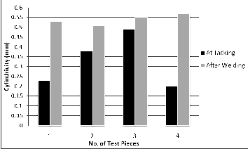
Fig. 8 Cylindricity values in Case – II & III
The rest of the data was obtained for case-II, without backing system i.e. job No. 1 & 2 and for case-III, without Backing and
IJSER © 2013 http://www.ijser.org
International Journal of Scientific & Engineering Research, Volume 4, Issue 12, December-2013 749
ISSN 2229-5518
alignment fit up i.e. Job No. 3 & 4 as shown in figure 8. Higher value of cylindricity in both cases is noticeable. A mean value of 0.30, 0.52 & 0.34, 0.56 in respective cases shows the significant impact of backing fit up and alignment tooling.
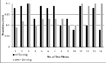
5 Measurement of Roundness.
Roundness is measured with the same environment at 25 mm across the weld line. The values are obtained at both stages of welding. The obtained results somehow interesting. In case-I mostly the roundness values decreased after welding. Figure 9 shows that in one job it remains constant and only two jobs out of 10 facing higher values. For test pieces 11 to 12 in case-II and 13 to 14 in case-III roundness values are high at welding side.
Fig. 10 (a)-Weld Bead with backing tool. Introduction of backing tool increases the width of the bead. (b) Narrow bead
in the absence of copper backing.
So introducing and extending the size of the backing support
not only provides alignment both in radial and axial direction
but also has the impact on weld bead geometry. However it
has an adverse effect also like drawing too much heat from the
welding arc. In this case higher current must be deployed ini-
tially to get enough heat input for required penetration. This
larger value of ampere however put up unnecessary tempera-
ture lay up in the tool assembly and at weld joint as well. This
higher heat input can lead to introduce welding defects such as cracks in weld or even in HAZ, seen in some cases as shown in figure 8.So progressive control of current for mini- mum heat input is necessary.
Fig. 9 RIoundnJess Data
.
Fig. 8 HAZ and Base metal crack due to Excessive Heat in- put in a test piece.
7 Conclusion
6 Effect of Backing Contact on Weld Bead
From figure 10 (a), it is shown that the use of copper backing has the significant influence on weld bead geometry. In case-I, the width of the weld bead is higher than in case-III. It is due to increase of the “Heat Input”. More heat is absorbed in the presence of copper backing.
(a)
(b)
In aforementioned work, two cylindrical tubes with different
lengths having low thicknesses were welded successfully. The
effect of tacking and welding on circularity and cylindricity
was observed. It is found that in the presence of internal back-
ing and external restraints, perfect matching of abutting surfac-
es with good alignment seen. Slight increase in difference be-
tween tacking and welding observed. Due to the lesser distor-
tion the values of cylindricity and roundness are in their low-
est range. Higher values experienced when no fixture used. In
case of roundness, the values declining after circumferential
welding but in the absence of tooling (case-II, case-III), distor-
tion increases and the difference in values are obvious. The weld bead was analyzed with and without copper backing. Using internal backing wide bead observed with satisfactory profile. The work may further be extended by introducing
different types of backing materials like chrome-plated cop- per, anodized aluminium, stainless steel etc with and without grooves and their effects on welding parameters and bead geometry may be analyzed. Further, Finite element analysis can be performed to investigate the geometrical tolerances behavior and result may be validated with the experimental data.
IJSER © 2013 http://www.ijser.org
International Journal of Scientific & Engineering Research, Volume 4, Issue 12, December-2013 750
ISSN 2229-5518
REFERENCES
[1] G. Ravichandran, ”Prediction of Axis Shift Distortion during Circum- ferential Welding of Thin Pipes using the Finite Element Method, Welding Journal, Jan 1997, 39s-55s
[2] Howard B. Carry, “Modern Welding Technology,” 3rd Eddition, pp.
667-674, 1994.
[3] A M Malik, Ejaz M Qureshi, “Analysis of circumferentially welded thin-walled cylinders to investigate the effects of varying clamping conditions, Proceedings of the Institution of Mechanical Engineers, Part B: Journal of Engineering Manufacture, Volume 222, Number 7
/ 2008
[4] L.Forbes, “Internal Alignment Fixture and Welding Clamp”,U.S Patent No. 2,429,053, March 3 1945R.
[5] Walter J. Rozmus, Whitesboro, William A. Barnes, “Method and Apparatus for Uniting Tubular Members”, U.S. Patent No. 2,909,951, May 10 1955C.
[6] E.C.Chapman “Apparatus for welding”, U.S Patent No. 2,542,393, Feb 20 1951.
[7] C.H.Smith. “Butt welding fixture”, U.S Patent No. 3,008,035, Nov. 7
1961.
[8] John O Emerson. “Clamping and welding assembly”, U.S Patent No.
3,668,359, June 6 1972.
[9] William D Palmer. “Tool for preparing tube ends for welding”, U.S Patent No. 4,287,796, Sep 8 1981.
[10] Robert L Roddy. “Structure for aligning and butt welding tube ends.” U.S Patent No. 4,405,075, Sep 20 1983.
[11] Xavier F. Puisais “Internal chuck for butt welding two tubes.” U.S Patent No. 4,648,544, March 10 1987.
[12] John C. Hummel “Expandable tool for holding and aligning pipes to be welded.” U.S Patent No. 5,609,291, March 11 1997.
[13] Stanisław Adamczak “An analysis of errors of V-Block cylindricity
measurement with regard to the method parameters.” XVIII IMEKO World Congress, September, 17 – 22, 2006, Rio de Janeiro, Brazil.
[14] C. Costa Souza, Rosenda V. Arencibia, “A contribution to the meas- urement of circularity and cylindricity deviations”, ABCM Symposi-
um Series in Mechatronics - Vol. 5.
IJSER © 2013 http://www.ijser.org