International Journal of Scientific & Engineering Research, Volume 4, Issue 8, August-2013 74
ISSN 2229-5518
Effect of Temperature and associated
deformations on the gasket seal compression in a pressure vessel
1 Guruchannabasavaiah N G 2 Prof.Shanmugam 3 Arun L R
Abstract—This paper addresses the effect of temperature along with the internal fluid pressure on the gasket seal compression in a pressure vessel / pressurized piping systems through non linear finite element analysis. A pressure vessel comprises of a large container for housing the contents like piping, the heat exchanger, the reactants etc the contents of the vessel are at a high temperature of about 250ºC-300º C and at a high pressure too. A metal gasket with special elastic-plastic characteristics is trapped between the vessel and blind flanges and is compressed by the application of high bolt force. Usually several bolts (struts) are used to effect the leak proof characteristics at the flange joint. The bolts give rise to adequate contact pressure at the joint. The contents of the vessel which are at a high temperature cause the entire flange joint also to heat up. The joint due to this undergoes additional distortions. This distortion can cause the gasket compression to vary from the initial level of compres- sion. This results in variation of the contact pressure from the initial level which can cause leakage at the joint. Any leakage could be catastrophic as it could result in loss pressure and environmental pollution.This paper also addresses the amount of bolt force required to compress the gasket seal in a pressure vessel under the effect of pressure and temperature.
Index Terms— Ansys, elastic-plastic character, bolted flanges, internal pressure, metallic gasket, pressure vessel, Thermal distortion
—————————— ——————————
HE pressure vessel is a closed container designed to hold the gases or liquids at a pressure considerably different from ambient pressure. A flange is a method of connect-
ing pipes, valves, pumps and other equipments to form a sys- tem. A bolted flanged connection versus welded connection provides easy of access for cleaning, inspection and modifica- tion of a piping system. Flange joints are made by bolting two flanges together with a gasket between them to form a seal.
Different types of flange joints evolved over the centuries and were perfectly adequate for their duties at low pressure and temperature. However, high pressure, temperature and different external loading applications led to their sealing problems. Leakages (small and large) in flange joints, is a con- tinued significant safety concern both in terms of human life, environmental effect and cost. With the rapid advancement in technology for high pressure, high temperature and external loading applications, trends are changing. A flange joint must have adequate mechanical strength and good leak tightness, therefore it is important to evaluate the integrity and sealing performance at actual operating conditions.
Available design rules for flange joints are mainly con- cerned with the strength of the flanges and do not sufficiently consider for their sealing. In addition, these do not address the effect of any external loading on integrity and sealing perfor- mance. Present available design codes only consider internal pressure loading for the design of the flange joints. However, for the past few years, it has been realized that the actual load conditions should be considered for the design of the joints. Present available design methods and codes address only the structural strength of the flange joint under internal pressure
only and do not consider the effect of steady state and transi- ent temperature loadings. With the rapid advancement in technology for high temperature applications trends are changing. The leakage of bolted flange joints at high tempera- ture or during transient thermal is a well-recognized problem and makes the problem more complex under combined appli- cation of internal pressure and temperature.
2.1 Overview of the work
This work contains the results of finite element (FE) simulation of a Gasket in a pressurized flange vessels using ANSYS finite element software. These results are compared with the results obtained by analytical method. Based upon comparison of the results by using analytical methods and the finite element analysis, it is concluded that a good correlation between the results from the two different approaches has been observed. This analytical procedure has also been validated in this work. The analytical method yields results on the conservative side. The finite element analysis gives a complete picture of me- chanical behaviour of the gasket and design guidelines with- out costly experiments.
2.2 Problem definition
The problem concerns with the investigation into the sealing characteristics of a metal gasket at the interface of two pipes. The pipes carry a high temperature fluid at a high pressure. It is required to study the effect of thermal load on the perfor- mance of the sealing effect of the Gasket.
Due to the variation in the temperature of the fluid, the
IJSER © 2013 http://www.ijser.org
International Journal of Scientific & Engineering Research, Volume 4, Issue 8, August-2013 75
ISSN 2229-5518
gasket undergoes elasto-plastic deformation. The bolt load designed to compress the gasket may not be sufficient due to temperature distortion of the fluid. Many times it is required to go for high factor of safety while designing the flanges, nut and bolts and gasket to avoid leakages. So it is required to ana- lyse the effect of temperature and optimise the exact bolt force required to hold the gases or fluids.
2.3 Objective
I. A method is developed in the present research for modeling and investigating into the temperature dis- tribution in the joint and the thermal stresses and de- formations.
II. The variation of the contact stresses at the joint will be investigated. Recommendations will be suggested in case the deformations are excessive.
III. Usually in industries, the flange design is made by us- ing ASME standard codes. Sometimes it is very diffi- cult to select the bolt force where the boundary values exists, at that time we may select very high bolt force which is very high and it may need high strength bolts and more torque power. If we select less bolt force there will be chances of leakage. From this pro- ject we can easily judge the exact bolt load which is required to hold the flanges without leakage even though the flange is subject to thermal loads along with the internal pressures and contact stresses.
In this paper result of an extensive comparative experimental study of a gasketed and non-gasketed flange joint with differ- ent assemblies with different combined load combinations is carried out to investigate joint performance i.e. joint strength and sealing capability. Actual joint load capacities are deter- mined under both the design and proof test pressure with maximum additional external loading (axial and bending) that can be applied for safe joint performance.
In this analysis failure modes are identified with respect to the leakage concern. The causes are identified and the causes are mainly related to the internal pressure of the fluid, design of flanges, gasket, bolt and nut and temperature.
Face Gaskets Abdel-Hakim Bouzid and Hichem Galai
This paper analyzes the distribution of gasket stress and the
load change in bolted joints with full face gaskets. It proposes
a simple analytical approach capable of predicting flange rota-
tion and bolt load change during operation. The method is
based on the gasket-bolt-flange elastic interaction, including
flange rotational flexibility.
This paper investigated the operational parameters affect- ing the flange-gasket assembly for large diameter steel flanges. Clamping pressure needs to be carefully selected to get proper sealing of the flange-gasket assembly. In- creasing the clamping pressure will result in better contact pressure but at the cost of higher flange stress.
3.5 Finite Element Analysis of Contact Stress in a Full- metallic Pipe Joint for Hydrogen Pipelines Nan BU, Naohiro Ueno, and Osamufukuda
This paper reports a preliminary study on contact stress anal- ysis of a full-metallic bolted flange joint with the metallic gas- ket in bolt-up conditions. Because of shape and size of the con- tact interface in this pipe joint, direct measurement of the con- tact stress is difficult. Therefore, contact stress analyses have been performed numerically using a three-dimensional (3D) finite element method.
the effect of pressure and temperature.
In the previous work by Spence et al and Abid et al, only 2-D finite element modeling and analysis is performed for internal pressure loading only. In the present work, a detailed para- metric FEA is performed using elasto-plastic material model for combined internal pressure steady state and Transient thermal loadings. Half portion of combined bolt and gasket is modeled due to plane symmetry of bolt.
The material and material properties are listed in the below
table 1.
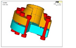
Fig 1shows the geometric details of the joint. The model con- sists of the vessel with vessel flange, the blind flange and
IJSER © 2013 http://www.ijser.org
International Journal of Scientific & Engineering Research, Volume 4, Issue 8, August-2013 76
ISSN 2229-5518
the gasket. Only a portion of the vessel close to the gasket is considered in the analysis. The joint comprises of 12 numbers of bolts. The vessel contains boiler up heated steam and operates at a high temperature of 300ºC.
Fig 2 shows the axisymmetric view of the geometric details of
the joint.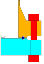
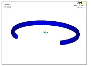
Fig 3 shows the geometric model of the Gasket.
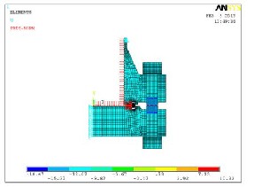
The vessel, the flanges, the gasket and the loads are all axi- symmetric. There are 12 numbers of bolts. Though the bolts exactly are not axi symmetric, they are quite closely spaced along the bolt hole circle making the arrangement nearly axi symmetric. It is known that axi-symmetric meshes enable more fine meshes as compared to solid meshes giving more accurate results. This will enable trying several iterations re- quired for optimization. It is as such worthwhile to consider the entire model as axi-symmetric considering the modeling and computational advantages.Fig 4 shows the axi-symmetric finite element mesh of the full joint.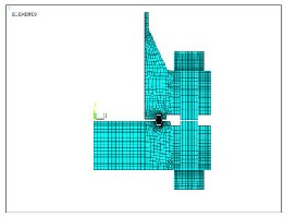
The elements generated are PLANE 182 (axi symmetric) for all elements. Appropriate material properties are given for the flange, the bolt and the gasket members.
The contact elements are surface to surface type as de- scribed below.
-TARGET169
-CONTA172.
There are six pairs of contact elements in the model-two be-
tween the nut faces and flanges and four between the gasket and flange female groves. The Gasket is Ring type and the material used is stainless steel 316:S316.
On to this FEM mesh are added the displacement boundary conditions and the loads.
Fig 5 shows the boundary conditions, the internal pressure load and the bolt loads that are applied on to the model.
IJSER © 2013 http://www.ijser.org
International Journal of Scientific & Engineering Research, Volume 4, Issue 8, August-2013 77
ISSN 2229-5518
Contact elements are generated between the faces of the nuts mating with the flanges. Likewise, contact elements are gener- ated between the gasket faces and the corresponding faces on the flanges.
Total number elements in the model= 2600
Total number of nodes = 3685
Boundary Conditions
Boundary conditions: UX=0 along the axis for the blind flange.
UY= 0 along the top horizontal line of vessel flange.
1. First apply the internal pressure load in the vessel and flanges. (=1500 psi = 10.33Mpa). Apply the bolt load
as well.
2. Compute the stress intensity in the flange joint.
3. Compute the gasket pressure at the contact zones.
4. Compute the equivalent temperature of the bolt in
deg C that would give the same gasket contact pres-
sure.
5. Carry out nonlinear thermal analysis applying inter-
nal and external thermal loads.
Continue the run in step 4 by applying the temperature loads
on to the joint that are computed in Step 5. Compute the Gas-
ket contact pressure under the combined thermal and internal
pressure loads.
Case Study 1
Loads applied:
1. Internal pressure, p= 10.33 MPa.
2. Force on flange = Effective area of flange up to gasket
* internal pressure.
Effective area= π * R2, where R= 158 mm.
Force on flange =810150 N.
This is the minimum force to be resisted by the bolts to keep
the flanges to touch the gasket. Any additional bolt pressure
will build the contact pressure at the gasket.
3. Let the bolt force be 1215225 N.
4. The equivalent bolt pressure = Force/ Bolt area.
= 1215225/65797.7= 18.47 N/mm2
This load is applied as pressure load on the bolt.
Finite element analysis has been carried out.
Fig 6 shows the deformation pattern of the flange joint. The
maximum vertical deformation at the blind flange is 0.119mm.
The peak stress intensity in the joint is 216Mpa.
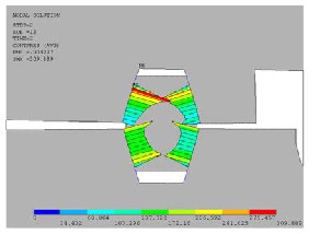
Fig 6 shows the contact stress at the gasket –flange interface.
The value at the lower left side is observed to be 98.2 MPa.
This value is more than the internal pressure of 10.33 MPa.It
appears that there is substantially adequate value of gasket
contact stress. But the question is that whether under thermal-
ly heated condition, is the gasket stress getting relieved? What
will be the gasket contact stress under the hot condition?
The following are the thermal loads on the flange.
1. Internal fluids at a temperature of 300 deg C.
The convective heat transfer coefficient is 14.5E-5 W/ mm2/
deg C.
2. External fluid (ambient air) is at 40 deg C.
The convective heat transfer coefficient is 2.5E-5 W/ mm2/
deg C.
Nonlinear thermal analysis has been carried out for the tak-
ing into consideration the contacts between the flanges and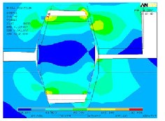
the gaskets and between the nuts and the flanges.
The next stage of the analysis involves application of this tem- perature field on the flange structure that was already stressed earlier due to bolt load and vessel internal pressure.
Fig 7 shows the deformation field under the action of thermal load, internal pressure load and bolt load. The Fig 7shows that the deformations have substantially increased to 0.895mm from the previous computed value of 0.1168mm.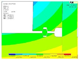
Fig 7 shows the deformation field under the action of thermal load, internal pressure load and bolt load. It is interesting to see that the gasket joint has lost contact with the joints on the right hand side. This speaks of imminent leak of internal pres- surized steam. This is in contrast to the earlier case which showed adequate contact pressure on all side of the gasket. This shows the plot of contact pressure between the gasket and flanges under the heated condition, but with the bolt force
IJSER © 2013 http://www.ijser.org
International Journal of Scientific & Engineering Research, Volume 4, Issue 8, August-2013 78
ISSN 2229-5518
still active. The contact stress on the left hand side is zero.
This analysis confirms the need for higher bolt load under
thermally loaded condition.
Similar analysis is carried out using different bolt loads as
tabulated in Table 2
In the Fig 9, contact stress and the deformation are 200Mpa and 0.224mm which are substantially adequate to maintain the gasket contact pressure.
Case 1 | Case 2 | Case 3 | |
Internal pressure(Mpa) | 10.33 | 10.33 | 10.33 |
Force on Flange (N) | 810150 | 810150 | 810150 |
Bolt Force N | 1215225 | 1620300 | 2430450 |
Bolt pressure(Mpa) | 18.47 | 24.63 | 36.94 |
Deformation on blind flange under bolt load and internal pressure (mm) | 0.119 | 0.224 | 0.414 |
Deformation on blind flange under bolt load, internal pressure and thermal load (mm) | 0.895 | 0.789 | 0.804 |
Thermal load ºC | 239.1 | 238.1 | 238.5 |
Maximum Stress inten- sity under internal pressure and bolt load Mpa | 216 | 389 | 456 |
Contact stress between gasket and flange inter- face due to internal pressure and bolt load MPa | 98.2 | 200 | 368 |
Contact stress between gasket and flange inter- face due to internal pressure, bolt load and Thermal load MPa | 0 | 0-25 | 191.7 |
Fig 8 shows the deformation and the stress intensities as per the case study 2.
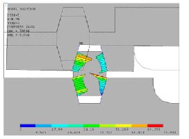
Fig 10 shows the contact pressure at the gasket –flange inter- face. Though the contact pressure is widely varying at the four flanks of the gasket, the value at the lower left side is 369 MPa.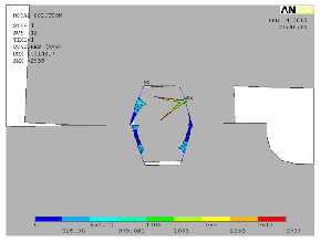
IJSER © 2013 http://www.ijser.org
International Journal of Scientific & Engineering Research, Volume 4, Issue 8, August-2013 79
ISSN 2229-5518
Analysis of a pressure vessel with super-heated steam at tem- perature of 300 deg C and pressure of 10.33 MPa has been car- ried out. The pressure vessel is closed with a blind flange and clamped with 12 numbers of bolts. A solid metal gasket of TJ type with octagonal section is selected as per ASME Section VIII. The internal diameter of the vessel is 254mm. Each bolt is M48.
Because of internal pressure, the force that is separating the vessel and blind flanges is 819150N. The minimum bolt force required to keep the flanges is as such 819150N. Additional bolt force is required to exert compressive pressure between the gasket and the flanges. Too low a contact pressure will lead to leakage while too high a contact pressure will imply high bolt forces and associated stress intensity in flange joint which is undesirable. Added to the problem is the thermal load. Due to the high temperature inside the vessel, convec- tion currents arise which lead to differential temperatures in the flanges. Under this influence, it is observed that the initial- ly applied bolt preload changed thereby changing the contact pressure at the gasket.
Three different bolt loading cases have been investigated in the thesis.
When the bolt preload is 1215225N, the initial gasket contact pressure was 98.2MPa. However on application of thermal load, the contact pressure became zero on the right side flanks. When the bolt preload is 1620300N, the initial gasket contact pressure was 200MPa. However on application of thermal load, the contact pressure became 45MPa on the left side flanks. On the right side flanks the contact pressure is less at about 25-30MPa.
When the bolt preload is 2430450N, the initial gasket contact pressure was 368MPa. However on application of thermal load, the contact pressure was 191.7MPa on the left side flanks.
Considering these, the initial bolt preload can be set at slightly higher than 1620300N.
Manufactured from one metal or a combination of metals in a variety of shapes and sizes for high temperature or pressure use. Due to the high pressures involved, the seating stresses are necessarily large to give sufficient gasket deformation to overcome any flange surface imperfections and to overcome the high system pressure forces.
The gaskets sit in a recess in the flange face, which has
23°angled walls.
1. Initial load requirement (Wm1) Methods
Wm1 = π b G y ……………. (1)
Here, b is width of gasket, G is effective diameter of seal and y
is seal pressure.
2. Operating load requirement (Wm2) Wm2 = πG2P/4 + 2bπ GmP ..… (2)
(2m – 1) 2 * 180 = y ……………... (3)
The factors ‘m’ and ‘y’ are the ‘gasket factor ‘and initial seating stress (psi) values respectively. The load-sealability character- istics of a gasket are quite complex. Incorporating these effects into a reliable flange design method has been the objective of designers for many years, and a number of flange design codes are now well recognized.
The ASME VIII gives a more conservative value for bolt load. The limitation in the code has led to research and develop- ment of alternatives such as the finite element method.
Y = 1500 psi.
From Eqn (3), m= 1.9.
B= gasket width = 15mm.
G= 312 mm
P= 10.33MPa
From qn (2),
Wm2= πG2P/4 + 2bπ GmP = 7 89 367.4 + 5 73 147.7 N
=13 62 514.1 N
This being a metal gasket, a higher bolt force is desirable be-
cause the metal is hard unlike softer gaskets used at lower
pressures. The higher force will compress the gasket and take
care of local unevenness of the flanges.
From FEM, the estimated bolt force is 1620300 N. This value compares well with analytical calculations.
[1] ABID, M., NASH, D. H. (2004). “Comparative study of the behaviour of conventional gasketed and compact non- gasketed flanged pipe joints under bolt up and operating con- ditions”.
[2] Power, D. J. (1997). A Study of Conventional and Uncon- ventional Flanged Pipe Joint Styles Using Non Linear Finite Element Analysis Techniques. M.Phil. Thesis.
[3] Abid, M. (2000). Experimental and Analytical studies of conventional (gasketed) and unconventional (non gasketed) flanged pipe joints (with special emphasis on the engineering of ‘joint strength’ and ‘sealing’). PhD Thesis.
[4] “ASME Boiler and Pressure Vessel Code, Section II, Part
D”, (1998). American Society of Mech. Eng., New York, USA.
Muhsen Al-Sannaa1 and Abdulmalik Alghamdi2 “Two di-
mensional finite element analysis for large diameter steel
flanges”
[5] Lake, G. and Boyd, G.,1957, “Design of Bolted Flanged
Joints of Pressure Vessels,”
Proceedings of IMechE, UK, Vol. 171, pp. 843-872.
[6] NAN BU, NAOHIRO UENO, and OSAMU FUKUDA Fi-
nite Element Analysis of Contact Stress in a Full-metallic Pipe
IJSER © 2013 http://www.ijser.org
International Journal of Scientific & Engineering Research, Volume 4, Issue 8, August-2013 80
ISSN 2229-5518
Joint for Hydrogen Pipelines

(Mb.No. +919538423022, Email: gurusky.1984@gmail.com) MTech Mechanical Machine Design, under the guidance of Prof.Shanmugam in Dept. of Mechanical Engineering at The Oxford college of Engineering Bangalore, Bom- manahalli, Hunasamaranahalli, Bangaluru- Karnataka. Re- ceived the B.E (Mach) degree from H.M.S Institute of Tech- nology, Tumkur in 2005.
The Oxford College of Engineering
Bangalore AUTHOR 3: Mr. Arun L R
The Oxford College of Engineering
Bangalore
IJSER © 2013 http://www.ijser.org