International Journal of Scientific & Engineering Research, Volume 6, Issue 2, February-2015 602
ISSN 2229-5518
Effect of Solidity on Flow Pattern in Kaplan
Turbine Runner
Ruchi Khare*, Vishnu Prasad**, Brijkishore ***
Index Terms: solidity; Kaplan turbine; efficiency; CFD; runner blade; axial flow reaction turbine
Hydro power plants meet one fifth of the total electrical power demand in world [10]. A small improvement in the hydrodynamic design and efficiency of turbine can make significant contribution to the supply of electric power. The flow in turbine space is 3D turbulent due to presence of stationary and rotatory blade rows. Hence assumptions are made in design of turbines and this leads to variation in turbine performance from design conditions.
It is therefore, necessary to predict the actual turbine performance before making prototype. The conventional method to predict the turbine performance is testing of turbine model. The model construction and testing is costly as well as time consuming when several modifications in the design are needed. Also, it provides characteristics in terms of global parameters of turbine as a whole and it is difficult to get characteristics in terms of local parameters or for individual component [3]. The advancements in numerical methods, computational power and memory of computers have made possible to carry out numerical flow simulation in complex turbine space by approximate solution of RANS equations governing the flow.
The overall performance of axial flow turbine depends not only on operating conditions but also the flow characteristics of individual components, mainly the runner [1]. The efficient design of the runner is of utmost importance. The amount of kinetic energy coming out of the runner depends mainly on the design of runner i.e. the blade profile and solidity of it. The ratio of circumferential spacing (pitch) and stream wise length (chord) of runner blade are known as pitch chord ratio and its inverse is known as solidity. It affects the hydrodynamics flow pattern as well as lift and drag on blade.
___________________________________________________
** Dr. Vishnu Prasad is Professor in Civil Engineering at M.A. National
Institute of Technology, Bhopal, Email: vpp7@yahoo.com
*** Brijkishore , M,Tech. student in Civil Engineering at M.A. National
Institute of Technology, Bhopal. brijkishore844@gmail.com
The solidity may be varied either by changing number of blade or chord length. In present case, solidity is varied by changing number of runner blade.
The work presented in this paper focuses on study the
effect of solidity of runner on the local and global
parameters of an axial flow hydraulic turbine. The 3D
flow simulation of a Kaplan turbine is carried out
changing the solidity of runner. The trend of computed efficiencies of the existing turbine are found to have close comparison with that of experimental results.
The pressure and flow parameters are computed from the results of numerical simulation for different solidities of Kaplan runner and hub to tip variations of these parameters at inlet and outlet are presented in graphical form.
The 3D geometry of complete turbine space of an existing model of Kaplan turbine consisting of casing, stay ring, distributor, runner and draft tube has been used for numerical simulation. Out of these components, runner is rotating and all other components are stationary. Therefore, each component of turbine has been modeled separately in Ansys Workbench and then assembled through proper interfaces for simulation of turbine as whole. The existing model of Kaplan turbine has a spiral casing, stay ring with 12 stay vanes, 28 guide vanes, runner with 4 blades and elbow draft. The four variants of 400mm diameter runner with 3 ,4, 5 and 6 number of blades have been modeled to get variation in solidity. The runner blade is divided into 10 sections between hub
IJSER © 2015 http://www.ijser.org
International Journal of Scientific & Engineering Research, Volume 6, Issue 2, February-2015 603
ISSN 2229-5518
to tip and section wise values of the solidity for 3, 4, 5 and
6 blades are mentioned in Table 1.
(b) 4-bladed runner
No. of Blades | Section-wise solidity | |||||||||
No. of Blades | I | II | III | IV | V | VI | VII | VIII | IX | X |
3 | 0.98 | 0.87 | 0.81 | 0.76 | 0. 72 | 0.69 | 0.66 | 0.63 | 0.59 | 0.53 |
4 | 1.31 | 1.17 | 1.07 | 1.01 | 0. 96 | 0.92 | 0.88 | 0.84 | 0.78 | 0.71 |
5 | 1.63 | 1.46 | 1.34 | 1.27 | 1. 20 | 1.15 | 1.10 | 1.05 | 0.98 | 0.88 |
6 | 1.96 | 1.75 | 1.61 | 1.52 | 1. 44 | 1.38 | 1.32 | 1.26 | 1.17 | 1.06 |
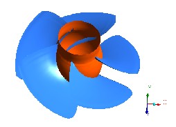
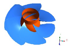
The assembled geometry of complete Kaplan turbine model is shown in figure 1. The runner with different number of blades and solidities are shown in figure 2.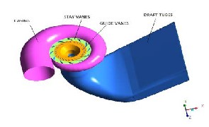
Fig. 1. Complete 3-D Kaplan Turbine model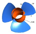
(a) 3-bladed runner
(c) 5-bladed runner
(d) 6-bladed runner
Fig. 2. Runners with different solidities
The mesh generation is a technique to discretize whole domain into small tetrahedral elements. The vertices of these elements are called nodes and flow variables are calculated at these nodes. The quality of mesh affects accuracy of numerical simulation to a large extent[4]. The unstructured mesh of tetrahedral elements in all components has been used and checked for mesh quality. The complete assembly is discretized in approximately thirty eight lakh elements and seven lakh nodes. The mesh of complete geometry with 4 blade runner is shown in figure 3.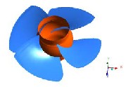
IJSER © 2015 http://www.ijser.org
International Journal of Scientific & Engineering Research, Volume 6, Issue 2, February-2015 604
ISSN 2229-5518
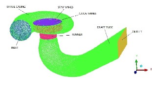
Fig.3 Meshing of complete turbine assembly
The specification of boundary conditions plays important role in the numerical flow simulation inside the turbine space and improper boundary conditions may lead to erroneous results [5]. The simulation is carried out at constant mass flow rate as 6200 Kg/s which is specified at casing inlet as inlet boundary condition. The outlet boundary condition is specified at draft tube outlet as relative static pressure equal to 0 Pa. The reference pressure is taken as 1 atm. The SST κ-ω turbulence model has been used due to curvatures in flow path and rotating flow in runner. The walls of all domains are assumed to be smooth with no slip. The flow simulation has been carried out using ANSYS CFX code which is based on solution of RANS equations by finite volume method.
The values of pressure and velocity at nodes obtained from numerical simulations are used to compute the mass average values of local and global dimensionless parameters [1,2]. Following formulae were used for computation
The simulation is carried out at speed factor 46.57 and discharge factor 0.359 at guide vane opening is 40°degree which is the best efficiency point obtained in experimental results for four blade runner. It was found that the efficiency obtained from numerical simulation for four blade runner at best efficiency point under the same operating conditions is 92.24% which is very close to the experimental value which is 92.06% [3]. The numerical simulation results for constant guide vane opening and speed gives the pressure and velocity distribution along the grid lines in span wise direction at different solidities of the runner. The non-dimensional parameters using the expressions given above are computed from hub to tip of the runner.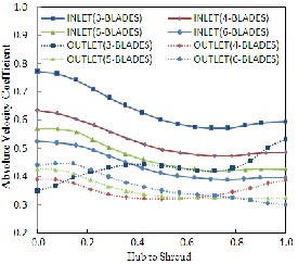
The hub to tip variation of normalized absolute velocity is plotted in figure 4. The absolute velocity decreases from hub to middle of span and then becomes nearly constant up to tip. Whereas it has reverse pattern at the outlet i.e. it is increasing with solidity till half span of the runner but decreases with solidity at tip.
Net head Hn =![]()
TPCASI−TPDTO
γ
(1)
Fig. 4 Hub to tip variation of absolute velocity![]()
Absolute velocity coefficient 𝛼 = 𝑉
�2𝑔𝐻𝑛
![]()
Whirl velocity coefficient 𝛽 = 𝐶𝑢
�2𝑔𝐻𝑛
![]()
Relative velocity coefficient 𝜆 = 𝑊
�2𝑔𝐻𝑛
![]()
2 −𝑊 2

(2) (3) (4)
Degree of reaction 𝜑 = 𝑊2 1
(5)
Flow deflection
2𝑔𝐻𝑛
ε = β1 − β2 � (6)
![]()
Speed factor 𝑛11 =
�𝑔𝐻𝑛
(7)![]()
𝑄
Discharge factor
𝐷2 �𝑔𝐻𝑛
(8)
IJSER © 2015 http://www.ijser.org
International Journal of Scientific & Engineering Research, Volume 6, Issue 2, February-2015 605
ISSN 2229-5518
Fig. 5 Hub to tip variation of relative velocity
In figure. 5, the relative velocity increases from hub to shroud at all solidities and it is decreasing with increase in solidity at inlet and outlet because of change in flow angle from hub to tip. The decrease of absolute velocity (figure 4) increase in relative velocity (figure 5) from inlet to outlet confirms the characteristic of reaction turbine.
It is seen from figure 6 that the whirl velocity increases from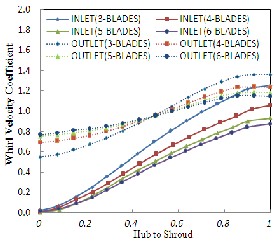
hub to shroud at all solidities and increases with increase in solidity at inlet. At outlet there is increase in whirl velocity with solidity up to mid span of the runner but starts decreasing after this it has reverse pattern up to shroud.
Fig. 6. Hub to tip variation of whirl velocity at inlet and outlet of Runner
The variation in degree of reaction with solidity shown
in fig 7 indicates that the static pressure energy changes from inlet to outlet of runner with reference to total energy supplied to turbine. In case of axial flow turbine it is found to be increasing with solidity because of increase in relative velocity from inlet to outlet with solidity.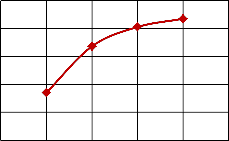
0.8
0.7
0.6
0.5
0.4
Fig. 7. Variation of degree of reaction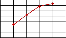
20
18
16
14
12
10
8
6
2 3 4 5 6 7
Fig. 8. Variation of flow deflection
It is observed from figure 8 that the flow deflection is also increasing because change in flow velocity with solidity.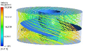
The streamline pattern within runner as shown in figure 9 indicates the difference in velocity on the two surfaces of blade[7]. The velocity on suction (lower) surface is more than pressure (upper) surface. Further it is seen that there is sharp increase in velocity on suction surface with increase in solidity.
(a) 3-bladed runner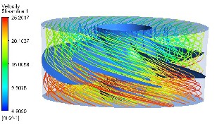
(b) 4-bladed runner
0.3
2 3 4 5 6 7
(c ) 5-bladed runner
IJSER © 2015 http://www.ijser.org
International Journal of Scientific & Engineering Research, Volume 6, Issue 2, February-2015 606
ISSN 2229-5518
6-bladed runner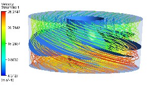
(d)
in Kaplan turbine” Science in china Series E-Tech
Science, 1137-1148, China.
[2] Consul C.A., Willden R.H.J, Ferrer E. , McCulloch M.D.,2009 “influence of solidity on the performance of cross-flow turbine” Proceedings of the 8th European Wave and Tidal Energy Conference, Uppsala, Sweden.
[3] Prasad Vishnu, Gehlot V.K., Krishnamachar P. , 2009
“CFD approach for design optimisation and validation for axial flow hydraulic turbine”, Indian Journal of Engineering and Material Science,pp 229-236.
[4] Singh Punit, Nestmann Franz, 2010 “Exit blade
geometry and part-load performance of small axial flow
propeller turbines: An experimental investigation”
Fig.9. Streamlines within runner at different soidities
It is found from numerical flow simulation results that flow parameters change from hub to casing. The velocty is increasing with solidity of axial flow turbine runner. Absolute velocity is decrasing from hub to tip but whirl and relative velocity are increasing from hub to tip both at inlet and outlet. The effect of solidity on flow parameters is observed more at outlet as compared to inlet. The flow deflection is increasing from inlet to outlet. The degree of reaction increases with solidity. The decrease in absolute velocity and increase in whirl velocity from hub to tip at inlet and outlet at all solidities confirms characteristics of axial flow reaction turbine.
g - acceleration due to gravity v - absolute velocity (m/s)
D - diameter of runner
Cu - whirl velocity
g - acceleration due to gravity ( m/s2) Hn - net head (m)
n - rotational speed of runner (rpm) Q - discharge (m3/s)
TPCASI - total pressure at casing inlet
TPDTO - total pressure at draft tube outlet
W - relative velocity (m/s)
W1 - relative velocity at inlet (m/s) W2 - relative velocity at outlet (m/s) β1 - relative flow angle at inlet
β2 - relative flow angle at outlet
Ύ - specific weight of water
[1] ShuHong LIU, Jie SHAO, ShangFeng WU & YuLin
WU, 2008 “Numerical simulation of pressure fluctuation
Institute for Water and River Basin Management (IWG),
University of Karlsruhe, Kaiser Str. 12, D 76128
Karlsruhe, Germany.
[5] Singh Punit , Nestmann Franz, 2011 “Experimental
investigation of the influence of blade height and blade number on the performance of low head axial flow turbines” Renewable Energy 36 pp 272-281.
[6] Yulin Wu, Shuhong Liu, Hua-Shu Dou , Shangfeng Wu,
Tiejun Chen, 2012 “Numerical prediction and similarity
study of pressure fluctuation in a prototype Kaplan turbine and the model turbine” Elsevier ltd pp128–142.
[7] Hyen-Jun Choi, Mohanmmed Asid Zullah, Hyoung- Woon Roh, Pil-Su, Sueg-Young Oh, Young-Ho Lee,
2013, "CFD Validation Of Performance Improvement of
a 500 KW Francis Turbine" Renewable Energy, Vol..54, pp-111-123.
[8] Diaelhag Khalifa, 2013 “Simulation of an axial flow turbine runner’s blades using CFD” AIIC 2013, 24-26, Azores , Purtugal.
IJSER © 2015 http://www.ijser.org