International Journal of Scientific & Engineering Research, Volume 5, Issue 3, March-2014 893
ISSN 2229-5518
Effect of Length and Apodization on Fiber Bragg
Grating Characteristics
Rakesh Kumar Gumasta, Dr. Anubhuti Khare
Abstract— Fiber gratings have a growing impact on the fiber optic communication industry. The simulation result of the reflectance of the uniform and apodized fiber bragg grating (FBG) are presented. Various apodization technique is useful to reduce secondary lobes or side lobs of reflection spectrum of fibre bragg grating. The effect of FBG length and apodization profile are presented
Index Terms— Fiber Bragg Grating (FBG) , Optical add drop multiplexer (OADM) , Dance Wavelength Division Multiplexing (DW DM), Optical circulator (OC) ,
1 INTRODUCTION
—————————— ——————————
Fiber Bragg Gratings (FBGs) are most commonly used as wave- length selective reflector. Fiber Bragg gratings are spectral fil- ters based on the principle of Bragg reflection. They typically reflect light over a narrow wavelength range and transmit all other wavelengths. When light propagates by periodically alternating regions of higher and lower refractive index, it is partially reflected at each interface between those regions. If the pitch of the rating is properly designed, then all partial reflections add up in phase and can grow to nearly 100%, for a specific wavelength even if the individual reflections are very small. The condition for high reflection is known as Bragg condition. For all other wavelengths the out of phase reflec- tions end up cancelling each other, resulting in high transmis- sion. Fiber grating can be classified into two types.
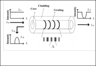
First one is Bragg Grating and another is Transmission Grating. Bragg grating favors coupling between travelling in opposite directions. They are also called reflection gratings or short-period gratings. On the other hand, in transmission grat- ings, coupling occurs between modes travelling in the same direction. Transmission gratings are also referred to as long period gratings.
Fig. 1. Basic Fiber Bragg Gratting
————————————————
• Author Rakesh Kumar Gumasta is currently pursuing masters degree program in digital communication from UIT- RGPV-Bhopal ,India, Mob-
9893783704. E-mail: rakeshgumasta44@gmaill.com
• Co-Author name is Dr. Anubhuti Khare Associate Professor in Electronics and communication department, UIT- RGPV,Bhopal,India. E-mail:
anubhutikhare@mail.com
The reflected wavelength is mainly determined by the period of the grating. Most common applications of fiber gratings in fiber optic communications are as add-drop filters in WDM systems, gain flatteners and pump stabilizers for EDFA’s, wavelength selective reflectors for Raman amplifiers, Dispersion compensa- tors for long-haul systems, encoder for CDMA systems.
2 THEORY
There are various methods available to solve the field relations numerically inside gratings in order to calculate the reflection and transmission spectra of fiber Bragg gratings. The well- known methods include:
• The transfer matrix method.
• Rouard’s method.
• The Gel’Fand -Levitan-Marchenko inverse scattering mathod.
• The Bloch theory method.
• Numerical integration to solve the coupled-mode equa- tions
2.1 Coupled Mode Theory
For Fiber gratings allow considerable energy exchange be- tween two or more fiber modes. The phase matching between different modes is achieved by the periodicity of the index change; the amplitude of modulation of index change, the average refractive index, and the period of the perturbation fully characterize a grating. These parameters can vary along the length of a grating, and they determine the frequency spectrum of the grating.
In the presence of a periodic perturbation of the refractive
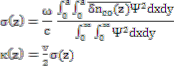
index, the wavelength for which the coupling between two modes is maximized is given by the following resonance con- dition:
 (1)
(1)
IJSER © 2014 http://www.ijser.org
International Journal of Scientific & Engineering Research, Volume 5, Issue 3, March-2014 894
ISSN 2229-5518

Where  and
and  are the propagation constants of the two modes, and is the period of the index modulation. In a fiber
(13)
bragg grating the first order diffraction usually dominates, so
we can consider that m=1. By considering β2 is less than 0 and
by assuming that the two modes are identical i.e. β1 = -β2 , we
get the resonant wavelength for bragg reflection
By solving the equation (8) and (9) and by passing the condi- tions A(0) = r(0) = 1 and B(L) = s(L) = 0,we obtain the ampli- tude and power reflection coefficients ρ and R
 (2)
(2)


Coupled mode theory is considered to be a good approach to calculate the spectral response of bragg gratings. Let us con- sider two identical modes propagating in opposite directions through a bragg grating, and denote them and B .
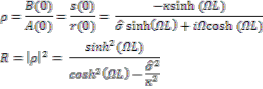

Where .
(14)
(15)
Due to the periodic refractive index perturbation, the coupling
coefficient will have a “DC” (period-averaged) component,
and an “ac component”
 (3)
(3)
where
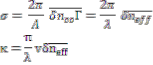
Given the fact that for most applications single-mode fiber is used, it is useful to calculate the coupling coefficient for a Bragg grating coupling the mode LP01 to the opposite propa- gating mode LP01 :
(16)
Ψ is the transverse profile of the identical modes. a is the core
radius of the fiber.
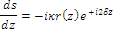
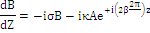
The presence of the periodic index perturbation causes the
two modes to be coupled such that their amplitudes A and B
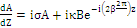
will vary along the propagation axis (z-axis) as follows:
(4)
(17) where  = Г
= Г and Г is the confinement factor of the mode.
Maximum reflectivity Rmax for a bragg grating:
 (18)
(18)
At the wavelength
 (19)
(19)
We can define the detuning δ to be
(5)
(6)
From equation (19) it can be seen that the wavelength λmax at which the maximum reflectivity occurs drifts from the initial
design wavelength λD by a factor of  λD.
λD.
for a uniform bragg grating to define the bandwidth between
the first zeros:
Let us introduce another “dc” self-coupling coefficient:

It is also useful to introduce this substitution

(7)
(7)
(8) (9)
(20)

Using above equation it is easy now to design a uniform fiber bragg grating and to calculate its reflectivity spectrum. When designing a uniform bragg grating at a given wavelength, the only two parameters we have to worry about are the length L and the index change of the garting. We observe from
To solve this system, a new substitution is required:

(10) (11)
Which gives the following system:
 (12)
(12)

equation (18) that the maximum reflectivity Rmax is a function of the coupling coefficient κ and the length of the grating L, and from equation (17) ac coupling coefficient κ depends only on  It is obvious that the maximum reflectivity increases with the product κL.For uniform grating the visibility v is constant along the entire grating, and is equal to 1. Therefore, we can rearrange the equation (20) as follows:
IJSER © 2014 http://www.ijser.org
International Journal of Scientific & Engineering Research, Volume 5, Issue 3, March-2014 895
ISSN 2229-5518
(21)
The bandwidth of a non-chirped fiber bragg grating is nar-
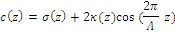
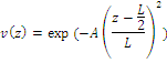
rower for longer grating, and is wider for larger index chang- es. This valid for all non-chirped bragg gratings (not just uni- form). However, if we want our strong grating to be narrow as well, we have to consider a longer grating with smaller index change. We also have to take into account the fact that the grating may become saturated .Since the grating has already met 100% reflectivity, increasing the strength κL will only af- fect the bandwidth of the grating. All uniform fiber bragg gratings have secondary lobes, which become larger in magni- tude as the grating reflectivity increases. The process of elimi- nating the secondary lobes by designing a grating with a non- uniform index change along its length is called apodization. For apodized gratings, the visibility v(z) is not constant along the length of the grating. The function after which the visibil- ity v varies with length z is called apodization function. There are various type of apodization function such as gaussian , Raised-Cosine, Hyperbolic-Tangent. Since Gaussian function simplifies the analysis by being an auto fourier transform, we can use the following Gaussian apodization:
3 SIMULATION RESULT
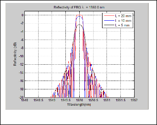
Fig. 2. Reflation spectram of FBG with different
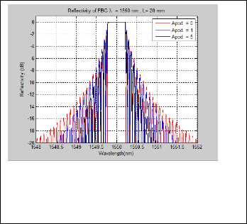
Figure 1 shows the effect of length of fiber bragg grating on reflection charecteristics of uniform fiber bragg grating. Its clear from figure that as we increase FBG length the peak re- flectivity is increased but side lobs also increases . Figure 2 shows the effect of apodization factor on reflection characteris- tics of fiber bragg grating of length 20 mm. It’s clear from fig- ure that as we increase apodization factor the maximum re- flectivity is constant but the side lobe power is reduced.
Fig. 3. Reflation spectram of FBG with different apodiza- tion factor
.References
1. Xuefang Zhou ; Gongquan Liang ; Tianshu wang “An Optical Add- Drop Multiplexer Design Based on Fiber Bragg Gratings” Electronics and Optoelectronics (ICEOE), 2011
2. Jen-Fa Huang, Chih-Ta Yen, and Ying-Wei Tu “Reduction of Linear Crosstalk Over Waveguide GratingBased OpticalCDMA Cod- ers/Decoders” Optical Society of America 2010 VOL. 2, NO. 11
3. An Vu Tran ; Wen De Zhong ; Tucker, R.C.; Lauder,R. “Optical Add Drop Multiplexers with Low Crosstalk” Photonics Technology Letters, IEEE 2001,Volume 13, issue 6 , page 582-584
4. Karim, M.R. ,S.P. Majumder “Crosstalk Modeling and Analysis of FBG-OC-Based Bidirectional Optical Cross Connects for WDM Net- works” IEEE 2009
5. Chisholm, k.E. ; Everall L.A. ; Williams J.A.R.;Bennion I Liux ; Delarue R.M. ; Aitchison J.S . “ Apodised Fiber Bragg Grating Design Subject to Length Constraints” Optical communication,1998,24th European Con- ference on Volume 1
6. Mahiuddin, M. ; Islam, M.S. "Performance Limitations In Fiber Bragg
Grating Based Optical Add-Drop Multiplexer Due To Crosstalk” Computer and Information Technology (ICCIT), 2010 13th Interna- tional Conference on page 170-174
7. Neves, P.R. Jr. ; Kuller, F. ; Marconcin, C. ; Kalinowski, H.J.. ; Fabris,
J.L. ; Pohl, A.A.P. “Experimental and Simulation Analysis of Unbal- anced Mach- Zehnder Fiber Bragg Grating OADM” Microwave and Optoelectronics, 2005 SBMO/IEEE MTT-S International Conference on
8. Urino, Y. ; Ofusa, N. ; Saito, T. ; Shimoda, T. ; Hanada, T. " Optical Add-Drop Multiplexer With Grating-Loaded Directional Cou- pler” Lasers and Electro-Optics, 1999. CLEO/Pacific Rim '99. The Pa- cific Rim Conference on vol.4 Page(s): 1141 - 1142
9. I-Yu Kuo ; Yung-Kuang Chen "In-Service OTDR-Monitoring- Supported Fiber-Bragg-Grating Optical Add-Drop Multiplexers” Photonics Technology Letters, IEEE 2002
10. Aswathy, M.S. ; Pournamy, S.S. ; Gopakumar, V.T. ;Mahadevan
Pillai V.P. ; Madhusoodhanan, M. ; Srinivasan, B. "All Optical Integra- tor Based on FBGs and Fabry-Perot Fiber Bragg gratings” Fiber Optics and Photonics 2012 International Conference on
IJSER © 2014 http://www.ijser.org