International Journal of Scientific & Engineering Research, Volume 6, Issue 1, January-2015 560
ISSN 2229-5518
Effect of Cutting Parameters on Surface Finish when Turning Nitronic 33 Steel alloy
Vincent A Balogun*1, Isuamfon F. Edem2, John Bonney3, Emmanuel Ezeugwu4, Paul T. Mativenga2
1College of Engineering, Department of Mechanical Mechatronics Engineering, Afe Babalola University, Ado Ekiti, Nigeria
2School of Mechanical, Aerospace and Civil Engineering, The University of Manchester, Manchester M13 9PL, United Kingdom
3Faculty of Engineering, Science and the Built Environment, London South Bank University, United Kingdom
4Air Force Institute of Technology Kaduna, Nigeria
*Corresponding author: E-mail: balogunav@abuad.edu.ng, TEL: +234-803-643-4484
Abstract— Nitronic 33 steel alloys are metallic alloys that exhibit characteristics such as high strength-to-weight ratio, outstanding corrosion and erosion resistant properties, and the ability to withstand cryogenic conditions and elevated temperatures. These characteristics of Nitronic 33 steel alloys make it popular in the fabrication of chemical processing, pollution control, aerospace equipment, and for steam and autoclave applications. Nitronic 33 steel alloy is classified as difficult-to-cut materials because of its high nitrogen content and the capability to form martensite as a result of high temperatures generated during mechanical machining and other subtractive manufacturing processes. This resulted in increased capacity and tooling cost during manufacturing. Therefore, there is the need to evaluate the optimum parameters when machining this alloy for sustainable and resource efficient machining. In this work, tool life, tool wear, surface roughness, cutting forces and power demand when turning Nitronic 33 steel alloy under different cutting environment were investigated. The result presented an optimum turning conditions at which Nitronic 33 steel alloy can be manufactured with minimum tool wear and surface integrity. The research outcome also addresses some of the problems encountered during the high speed machining of Nitronic 33 steel alloy that could influence manufacturing cost reduction. This work will also aid the general understanding of Nitronic 33 steel alloy with respect to sustainable and resource efficient machining.
Index Terms— Austenitic stainless steel, cutting parameters, dry cutting, high pressure cooling, nitronic 33 steel, tool wear characteristics, uncoated carbide tool.
1 INTRODUCTION
—————————— ——————————
ustenitic stainless steels are stainless steel materials which have austenite. They have an FCC (face centered cubic crystal) structure as their primary phase and are
mostly resistant to environmental variables. Austenitic stain- less steels contain chromium and nickel as the main alloyed elements. They are resistant to chemical reactions (i.e. water, gases, acids, bases, etc) and electrochemical influences of the atmosphere [1]. The austenitic stainless steels also exhibit the work-hardening characteristics which resulted due to the for- mation of metastable austenite. Hence, unfavourable segmen- tal chips are formed during the mechanical machining pro- cesses [2].
Nitronic 33 steel alloy is a nitrogen-strengthened austenitic stainless steel that combines high yield strength with excellent toughness and ductility [3]. The alloy is one of the Johnson– Cook’s families of materials [4]. Nitronic 33 steel alloy was reported by Zart [5] to exhibit high resistant to environmental attack regardless of the chemical pollutants and changing en- vironmental conditions. The Armco bulleting [6] also stated that this alloy is aggressive to chemical attacks and has an un- changing functionality at cryogenic temperature ranges. Ni- tronic 33 steel alloy also has good weldability and low mag- netic permeability. These alloys are characterised by high yield strength, high ductility, and endure prolonged lifespan
as a result of the high nitrogen content in the chemical compo- sition. Subsequently, and as reported by Douthett [7], they are widely used in the fabrication of various industrial compo- nents applicable to the aerospace industries, power genera- tion, chemical processing equipment, bio-medical equipment and applications, defence and armour manufacture, pollution- control equipment, steam and autoclave applications etc. The applications and uses of Nitronic 33 steel alloys were also re- ported by Milani et al., [4]. Table 1 shows the chemical compo- sition of Nitronic 33 steel alloy.
Table 1: Chemical composition of Nitronic 33 steel alloy adopted from [8]
1.1 Machinability characteristics of Nitronic 33 steel alloy
From literature, Nitronic 33 steel alloy is classified to be among the difficult-to-cut materials with varying machinabil- ity problems. For example Zatz [9] reported that Nitronic 33
IJSER © 2015 http://www.ijser.org
International Journal of Scientific & Engineering Research, Volume 6, Issue 1, January-2015 561
ISSN 2229-5518
steel alloy encourages the formation of built-up edge at the tool-workpiece contact interface during a machining opera- tion. The built-up edge formation allows the chips formed to adhere strongly to the cutting tools during the mechanical machining process. The resultant phenomenon is the fracture and/or plastic deformation of the cutting tool when broken away [10]. In the analysis conducted by Lee et al., [11] to eval- uate the magnetic properties of Nitronic 33 steel alloy as an undulator vacuum chamber materials, reported several ma- chinability problems which could affect the linac coherent light source from the material surface. Nitronic 33 steel alloy is of particular interest because of its nonmagnetic properties and wider engineering applications [12]. Nelson [13] reported that during the mechanical machining of Nitronic 33 steel al- loy, high level of acoustic emission was recorded. This high level noise can be detrimental to the environment, machine operators and workshop staffs.
In the analysis conducted to investigate the adhesion phe- nomena in the turning of austenitic stainless steel and carbon steel, Gerth et al., [14] repoted that austenic stainless steel al- loys exhibited the difficult-to-cut characteristics. This was at- tributed to the work hardening phenomenon during the me- chanical machining operations and at the same time to the formation of martensite phase (a characteristics common with materials of high nitrogen content) [8]. This phase transfor- mation as a result of work hardening of the material during mechanical machining of austenitic stainless steel alloy result- ed to an increase in temperature at the tool-chip contact inter- face that causes plastic deformation of the cutting tool.
Hosseini et al., [15] reported that high temperature genera- tion at the tool-chip contact interface is a common phenome- non when machining austenitic stainless steel. High tempera- ture generation during mechanical machining is attributable to shorter tool life[16]. Likewise, Saravanan et al., [17] reported that the increase in the cutting force and temperature during an end-milling operation of austenitic steel alloys is essentially due to the iron-chromium-nickel composition of the alloy. A martensitic phase transformation formation is induced as a result of increased cutting temperature. This could increase the tooling cost of machining austenitic stainless steel alloys. Zhu et al., [18] reported that cutting temperature signal analy- sis is a novel idea that can be used to characterize the tool wear and predict tool wear status especially when machining nickel-based superalloys. Furthermore, during the analysis of the performance of cutting fluids when machining steels, Vieira et al., [19] reported that austenitic stainless steel alloys requires a higher total power demand. This is as result of in- creased cutting fluid flow due to high temperature at the tool- chip contact interface.
These characteristics exhibited by austenitic stainless steel alloys (i.e. high temperature, built-up edge formation, tool wear, etc) can be adopted to define the economic objectives of machining Nitronic 33 steel alloy (an austenitic stainless steel alloy). Few researchers evaluated optimum machining param- eters for machining different austenitic stainless steels. For example Korkut et al., [2] reported that poor surface finish and high tool wear are common phenomenon when machining austenitic stainless steel materials. Juneja and Seth [20] and Gerth et al., [14] reported that work-hardening is attributable
to poor machinability of these alloyed steels. Kalpakjian and Schmid [21] reported that cutting forces are higher when ma- chining austenitic steel alloy compared to unalloyed steel as a result of the work-hardening effect encountered during the mechanical machining processes.
Although the cutting and machinability of austenitic stain- less steel alloys has been the focus in general, little has been done to investigate the cutting and machinability characteris- tics of Nitronic 33 steel alloy in particular. Hence, the need to establish optimum cutting conditions for economic and sus- tainable manufacture of Nitronic 33 steel alloy. This is the fo- cus of this research. This will enhance both the economic and environmental objectives for resource efficient and sustainable manufacture of this alloy. In view of this, the impact of cutting variables on turning Nitronic 33 steel alloy with uncoated car- bide tool was investigated. Tool life, tool wear, cutting and feed forces, as well as surface roughness was evaluated.
For the purpose of clarification, the use of proper cutting tool coatings enhances wear behaviour of the cutting inserts, un- coated carbide tools were selected since it has been reported that uncoated carbide tools are also suitable for machining Inconel 718 [22] at sustainable and economic cost criterion. In a recent interview conducted by Diaz et al., [23] they revealed that sales of uncoated tools by RobbJack Corporation (a cut- ting tool manufacturer) represent 70% of their end mill sales. This shows an increasing trend in the use of uncoated carbide tools within the manufacturing industries. The primary moti- vations in cutting tool selection are based on the workpiece materials, machining operations and machining economic considerations.
1.2 Aim and objectives
This work is intended to characterise tool life, tool wear and surface finish, cutting force and feed force and power demand during the mechanical machining operations of Nitronic 33 steel alloy. This will enable the evaluation of the optimum turning parameters for resource efficient and sustainable manufacture of this alloy. To achieve this, turning operations were conducted on Nitronic 33 steel alloy with uncoated cut- ting tool at different cutting speeds and cutting environment. The tool wear were measured and classified in accordance with ISO Standard 3685 [24] for tool life testing.
2 EXPERIMENTAL SETUP
The turning tests were carried out on a Colchester Mastiff CNC Lathe which has a manually three-range gearbox and spindle speed output between 18 - 200 rpm, 48 - 605 rpm and
140- 1800 rpm respectively and an 11kW motor drive which can generate a maximum torque of 1,411 Nm. The turning op- erations were subjected to four different cutting environments i.e. dry, conventional, 7 MPa flood pressure and 9.7 MPa flood pressure. The workpiece material was Nitronic 33 steel alloy round bar of dimension 293 mm x 350 mm.
The workpiece material was clamped in a three jaw chuck supported with a live centre for adequate support and non- deflection turning. The turning tests were carried out using uncoated insert (SECO Grade 890) CNMG433-MR3-890 incor- porating a sintered in the chip breaker grove.
IJSER © 2015 http://www.ijser.org
International Journal of Scientific & Engineering Research, Volume 6, Issue 1, January-2015 562
ISSN 2229-5518
In order to standardise the cutting test, the tool rejection cri- teria were considered in relation to International Standard Organization, (ISO), 3685 [24] for tool life testing as shown in Table 2. The cutting parameters and cutting environment en- gaged during the cutting tests were as shown in Table 3 and the experimental setup is as represented in Figure 1.
Table 2: Excessive chipping (flaking) or catastrophic fracture of the cutting edge
Average flank wear (VB) (mm) | ≥ 0.3 |
Maximum flank wear (VBmax) (mm) | ≥ 0.4 |
Nose wear (VC) (mm) | ≥ 0.3 |
Notching at the depth of cut line or tool nose (VN) (mm) | ≥ 0.6 |
Surface Roughness (Ra) ( µ m) | ≥ 1.6 |
Table 3: Cutting conditions
wear, and nose wear were measured at a magnification of 25 times using the X and Y coordinates of the microscopes.
The cutting forces were measured using the three- component Kistler piezoelectric tool post Dynamometer and after each turning pass, when the machine tool was stopped, the surface roughness was measured at three different points on the machined surface using a Surtronic-10 (a portable sty- lus type instrument) measuring device. The stylus travel over the machined surface perpendicular to the machined surface and the relative displacement magnified electronically indi- cates the surface roughness value (Ra/ m). The measurement was repeated three times for repeatability of data ranges.
After the machining tests, samples of the machined surfaces were collected at different cutting velocity (i.e. 90, 120 and 150 m/min) and at different cutting environment (i.e. dry, conven- tional, 7 MPa and 9.7 MPa coolant supply). Samples of the re- jected cutting tools, based on the tool rejection criteria, for all the given cutting conditions, were also collected. The surfaces of the samples to be examined under the Scanning Electron Microscope (SEM) were etched and cleaned with acetone to remove oil stains, dust and adhering materials. Micrographs of the samples were obtained using Scanning Electron Micro- scope (SEM), Hitachi S530.
Workpiece
Tool insert
Kistler Dynamometer
Force signal acquisition system
3 RESULT AND DISCUSSIONS
3.1 Tool life characterisation after machining Nitronic
33 Steel
The relationship between the tool life and cutting speed is shown in Figure 2. It can be seen that as the cutting speed in- creases, tool life decreases. This trend is as expected since as the cutting speed increases, the cutting tool is subjected to highly localized stresses and high temperatures, which induce tool wear mechanisms and thus adversely affects the tool life, the quality of the machined surface and its dimensional accu- racy. There was generally an improved tool life at a cutting speed of 90 m/min of 5.167, 3.38, 3.02 and 2.83 minutes for dry,
9.7 MPa, 7 MPa and conventional cutting environment respec- tively. Although, Figure 2 shows that turning Nitronic 33 steel alloy under dry cutting environment showed an improved tool life when turning at a cutting speed of 90 m/min with un- coated carbide tool insert, the tool life decreases as the cutting speeds were increased to 120 and 150 m/min respectively.
Fig. 1: Machine tool setup
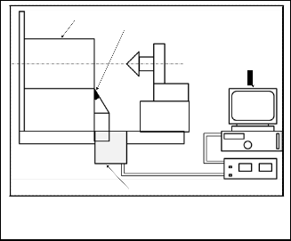
After each turning test, the machine tool was stopped and the cutting tools were examined under the microscope. The tool wear, (flank, nose, and rake face wear); forces (cutting force and feed force) and surface roughness were recorded. The feed rate was maintained at 0.15 mm/min and the cutting environment and coolant pressure were varied with different cutting environment (i.e. dry, conventional, 7 and 9.7 MPa flood pressure) engaged in turn.
Tool wear was measured with the MITUTOYO Tool Mak- ers Microscope after each turning test. The insert was removed from the tool holder and mounted on the MITUTOYO Tool Makers Microscope for examination. The flank wear, notch
IJSER © 2015 http://www.ijser.org
International Journal of Scientific & Engineering Research, Volume 6, Issue 1, January-2015 563

ISSN 2229-5518
Fig. 2: Variation of Tool Life with cutting speed after machining Nitronic 33 steel with uncoated carbide tool under various cutting environment.
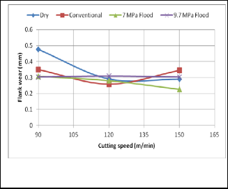
Fig. 4: Flank wear versus cutting speed after machining Nitronic
33 steel with uncoated carbide tool
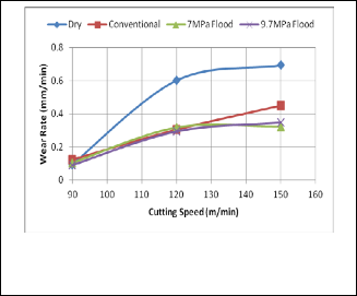
The decrease in tool life is attributable to the increase in temperature within the shear zone thereby causing an induced softening phenomenon at the tool cutting edges. This increases the wear rate of the cutting tool as shown in Figure 3. The conventional, 7 MPa and 9.7 MPa cutting environment exhibit- ed similar increasing trend of wear rate. The wear rate was 1% of the tool life at 90 m/min. This values gradually increases to over 65% for dry cutting environment as the cutting speed increases to 150 m/min. An average 30% decrease in wear rate was recorded between dry and cutting with fluids as the cut- ting speed increases. This is attributable to rapid cooling effect at the tool-chip contact inter phase that encourages the for- mation of discontinuous chips [25].
Fig. 3: Wear rate versus Cutting Speed after Machining Nitronic
33 steel with uncoated carbide tool
From Figure 4 and based on the maximum flank wear rejec- tion criterion (Table 2), the cutting insert engaged at 90 m/min under dry cutting environment was rejected as the flank wear values exceeded the maximum allowable. However, it took an average of 5 minutes to attain the maximum flank wear value of 0.48 mm.
Nose and flank wear were dominant when machining Ni- tronic 33 steel alloy as shown in Table 4. These wears pro- gresses under fluid cutting environment as the cutting speed increases during machining. Tool flank wear has been report- ed to increase when machining at higher cutting speeds but with Nitronic 33 steel alloy, it can be seen that the flank tool wear decreases for dry cutting environment and averagely constant for conventional, 7 MPa and 9.7 MPa cutting envi- ronment within the cutting speeds engaged (see Figure 4). This could be attributable to the formation of a built –up edge welded to the cutting edge of the tool. This tends to protect the cutting edge as the newly welded chip forms a tougher cutting edge of the tool.
Tool damage, either by wear or fracture, deteriorates the surface roughness and accuracy of the machined surfaces. Tool life can be determined based on the size and roughness of machined surface [17]. Tool wear is generally a gradual pro- cess. The rate of tool wear depends on cutting tools character- istics and geometry, workpiece materials, cutting environ- ment, cutting conditions and machine tools characteristics [1]. The tool wear observed after turning Nitronic 33 steel alloy are shown in Table 4. The main wear mechanisms observed when machining Nitronic 33 steel alloy with uncoated carbide in- serts and at the cutting conditions investigated were; 1) abra- sions wear on the rake and flank faces due to hard oxide inclu- sion, 2) diffusion controlled wear and 3) fatigue wear. It is a common occurrence for several tool wear mechanisms to be active simultaneously and to have a resultant effect on the tool [26]. Flank wear is the dominant tool failure mode in high speed machining [27] and there is no exception when machin- ing Nitronic 33 steel alloy.
Notch wear was also observed as shown in Table 4. This is characterized by excessive localized damage on both the rake and flank face of the insert at the depth-of-cut line. Notch wear is developed due to abrasion caused by work hardening of the workpiece material as it flows past the depth of cut region. This wear is worsened by burr formations especially when machining with uncoated carbide tools.
Tables 4a and 4b are micrographs of uncoated carbide tools after machining Nitronic 33 steel. The micrographs reveals
IJSER © 2015 http://www.ijser.org
International Journal of Scientific & Engineering Research, Volume 6, Issue 1, January-2015 564
ISSN 2229-5518
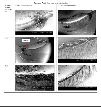
adherence of the Nitronic 33 steel alloy material to the cutting edge of the tool. This is generally observed in all cutting con- ditions investigated. It was observed that at 90 m/min and un- der dry cutting environment, the cutting tool shows signs of notch wear at the depth of cut line of the tool as shown in Ta- ble 5a. Also, the tool failure mode show both flank and crater wear. The crater wear is marked by smooth wear surface which is a characteristics of thermal wear mechanism such as diffusion wear. However, as the cutting speed increases, mate- rial adhesion phenomenon increases even at high pressure flood cooling. These characteristics are common with ductile materials. Generally, the worn tools show that the flank wear developed uniformly during the machining process. Increas- ing the cutting speed to 150 m/min for dry and adopting the conventional coolant method, the dominant wear mechanism was abrasive wear. This is evident by the parallel groves de- veloped at the flank face.
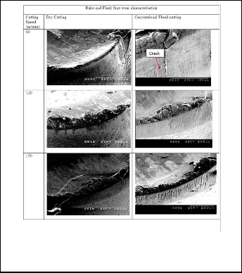
Fig. 4b: Tool Wear Assessment after Machining Nitronic 33 Steel alloy
Fig. 4a: Tool Wear Assessment after Machining Nitronic 33 Steel alloy
Table 4a also revealed a crack observed on the flank face of the cutting tool after machining Nitronic 33 steel with uncoat- ed carbide tool at a speed of 90 m/min under conventional flood cutting environment. This shows an evidence of high thermal gradient existence at the chip-tool cutting interface during machining which significantly affect the performance of the cutting tool. The uneven rapid cooling induced through the non-contact of the coolant at the tool-chip contact interface led to temperature differences. Similarly, after machining at a speed of 120 m/min and under a 7 MPa coolant pressure, a pronounced crack developed on the rake face of the uncoated carbide tool. Also, rake face (crater) wear was one of the pre- dominant wear observed when machining Nitronic 33 steel.
Tables 4a and 4b shows the rake face wear as recorded in the high speed machining of Nitronic 33 steel alloy. The rake face wear occurred in the form of a pit called the crater, which was formed at some distance from the cutting edge. Experi- mental results showed that increasing the cutting speed even further led to the increase of the crater wear area. This mode of tool wear is mainly due to high cutting temperature on the rake face as a result of extremely high temperatures (800–1000
°C) occurring at the vicinity of the cutting edge where the depth of crater wear is maximum [28]. The hardness of the cutting tool material decreases at such high cutting tempera- tures, which aggravates the wear on the tool rake face. High cutting temperature has been reported to accelerate diffusion and adhesion wear as well as plastic deformation of the cut- ting tool during high speed machining [27]. This is due to the fact that the tool–chip contact length is shorter in high-speed machining than at conventional cutting speed. This is because at high cutting speeds, feed rates are increased and chips formed disengage off the cutting tool faster than the rate at which they are formed. Therefore, the heat generated at the tool-chip interface is transported directly to the cutting tool.
3.2 Surface Roughness and integrity after machining
Nitronic 33 alloy steel
Figure 5 shows the relationship between average surface roughness and cutting speeds at the defined feed rate of 0.15 mm/min and under different cutting environments. A better surface finish was observed at all cutting conditions (i.e. cut- ting speed of 90, 120, and 150 m/min) as shown in Figure 5. The average surface finish recorded is below the recommended 1.6
µm surface roughness rejection criteria [29]. However, at a cutting speed of 150 m/min, and under conventional coolant flow condition, the surface roughness generated was approx-
IJSER © 2015 http://www.ijser.org
International Journal of Scientific & Engineering Research, Volume 6, Issue 1, January-2015 565
ISSN 2229-5518
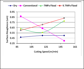
imately 50% lower than the recorded maximum.
Fig. 5: Average Surface Roughness versus Cutting Speed after Machining Nitronic 33 steel with uncoated under various cutting environment.
Also, it can be observed that the average surface roughness value for dry cutting environment is approximately constant irrespective of the cutting speed employed. An optimum sur- face roughness is obtained at a cutting speed of 150 m/min and under a conventional cutting environment when turning Ni- tronic 33 steel alloy with uncoated carbide insert. This is evi- dent when the machined surfaces were visualised with the Scanning Electron Microscope (SEM). The samples of the mi- crographs of the machined surface are shown in Figures 6 and
7.
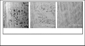
could be an area where dislocation of the bonding proves dif- ficult. These hard inclusions could be as a result of the chemi- cal composition of Nitronic 33 steel alloy which for example comprises of chromium, manganese alloy, carbon, etc. Chro- mium carbides are particularly formed when hard carbides are dispersed in a relatively soft matrix. The alloys forming chromium carbides are particularly effective because these carbides are usually present as relatively large micro- constituents, which offer large surface areas to the passage of abrasive material. However, the existence of high content of large chromium carbide makes machining of these hard fac- ings very difficult other than by grinding [30, 31] and/or laser- assisted machining [32]. The manganese composition within the alloy also contributes to the heat resistance of the material and high wear resistance.
3.3 Component Forces after Machining Nitronic 33
Steel
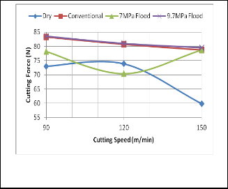
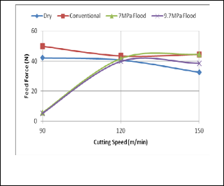
The relationship between the cutting force and feed force with cutting speeds after machining Nitronic 33 steel alloy is as shown in Figures 8 and 9 respectively. The component forces that are generated during mechanical machining could cause high compressive stresses at the tool nose and at the same time plastically deform the cutting tool edge and consequent- ly, would lead to accelerated nose and flank wear rates. From Figures 8 and 9, the feed force ranges between 15-50% of the cutting force at different cutting environment employed.
(a) 7MPa coolant flow (b) 9.7MPa coolant flow (c) Conventional coolant flow
Fig. 6: Micrograph of the machined surface after machining Ni- tronic 33 steel at speed of 90 m/min magnified x80.
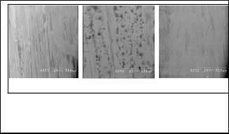
Fig. 8: Cutting Force versus Cutting Speed after Machining Ni- tronic 33 steel with uncoated carbide tool
(a) 7MPa coolant flow (b) 9.7MPa coolant flow (c) Conventional coolant flow
Fig. 7: Micrograph of the machined surface after machining Ni- tronic 33 steel at speed of 120 m/min magnified x80.
From Figures 6 and 7, noticeable black hard inclusion spots are observed. This are hardened material inclusions which
IJSER © 2015 http://www.ijser.org
International Journal of Scientific & Engineering Research, Volume 6, Issue 1, January-2015 566
ISSN 2229-5518
formula for power demand in machining as in Equation 1.

P = FcVc
60
(1)
Where P is the total cutting power demand in W, Fc is the cutting force in N and Vc represents the cutting velocity in m/min.
The variations of cutting power with cutting speed at dif- ferent cutting environments are shown in Figure 10.
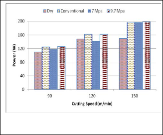
Fig. 9: Feed Force versus Cutting Speed after Machining Nitron- ic 33 steel with uncoated carbide tool
From Figure 8, higher cutting forces were recorded at a cut- ting speed of 90 m/min (under conventional coolant and
9.7MPa coolant flow). Increasing the cutting speed to 150 m/min resulted to a lower cutting force at dry cutting envi- ronment while dry cutting environment and 7 MPa coolant flow pressure recorded lower cutting forces at 90 m/min and
120 m/min respectively.
Figure 9 shows an increasing trend of the feed forces (as the
cutting speed increases) at 7 MPa and 9.7 MPa coolant flow
pressure and a decreasing trend for dry and conventional cut-
ting environments. A maximum feed force of 49.87 N was rec-
orded at 90 m/min under conventional coolant flow condition
and a minimum feed force of 5.32 N at 90 m/min under 9.7
MPa coolant flow condition. Mechanical machining at high
pressure coolant supplies resulted to increased feed forces
with increasing cutting speed. This is an expected phenome-
non and it is attributable to the inability of the coolant to sig-
nificantly reduce tool temperatures at higher speeds as a result
of the conditions of intimate contact, or seizure, that occur
over the major part of the chip-tool area. This part of the con-
tact area is not accessible to the water based lubricant (even at
high flow pressure) except for minimum quantity lubrication
(MQL) through a well defined nozzle angle [33, 34]. Some-
times, it is possible that cutting fluids can slightly penetrate to
the friction region at the rear of the tool-chip contact length, and also into the area created by the ragged edge of the chip, these effects do not greatly influence the temperature, cutting forces or tool life at higher speeds [35]. At lower cutting speed
conditions, there is the tendency of an increased coefficient of friction. This increases the cutting force and decreases the shear angle. A small shear angle along the shear plane increas- es the shear plane area thereby increasing the shear force that are required to produce stresses for deformation [25, 36].
3.4 Power Consumption when machining Nitronic 33 steel alloy at high speed conditions
The cutting power was estimated based on the theoretical
Fig. 10: Cutting power after machining Nitronic 33 steel alloy with uncoated carbide tool
It is clear from Figure 10 that Nitronic 33 steel alloy exhibit- ed minimum power demand at a cutting speed of 90 m/min under the dry cutting environment. At this cutting speed (i.e.
90 m/min) and from respective sections above, surface rough- ness and tool life are also at optimum values. The feed force and cutting force can also be said to be at their lowest value for this turning tests when compared to 120 and 150 m/min respectively. This further proves that unlike other materials, Nitronic 33 steel alloy materials are better machined at lower cutting speeds and under a dry cutting environment when machining with uncoated carbide tool.
4 CONCLUSION
This research investigated the cutting variables and their effect on tool life, surface finish, and forces when turning Nitronic 33 steel alloy material. The cutting speed is a fundamental quan- tity required for the estimation of tool life, wear rates and power demand and can have significant impact on the surface integrity of machined parts. The following conclusions were drawn as a result of this study:
• Rake face wear, flank wear, chipping, and cata- strophic tool breakage are the dominant wear pat- terns throughout the turning process.
• The occurrence of crater and abrasion wear was also noticed on the uncoated carbide insert at coolant flow pressure of 7 MPa and 9.7 MPa that resulted in the
IJSER © 2015 http://www.ijser.org
International Journal of Scientific & Engineering Research, Volume 6, Issue 1, January-2015 567
ISSN 2229-5518
rake face crack under fluid cutting condition.
• Flank wear showed a maximum at the speed of 150 m/min and higher feed rates increases the tool forces
• It was observed that tool life for uncoated carbide in- sert under a dry coolant flow condition at a cutting speed of 90 m/min was highest at 5.167minutes.
• Notch formation at the depth of cut line was predom- inant in the machining trials of Nitronic 33 steel
• Material adhesion, crater wear on the rake face and abrasion wear on the flank face are dominant wear modes after the machining of Nitronic 33 steel under the specified cutting conditions. Material adhesion was a constant occurrence throughout the turning tests.
• Crack on the flank face of the uncoated carbide tool was pronounced at a cutting speed of 90 m/min and
120 m/min under conventional coolant flow condition
and 7 MPa pressure respectively.
• For sustainable and resource efficient machining of Nitronic 33 steel alloy, it is proposed that a lower cut- ting speed of 90 m/min or less and under a dry cutting environment should be adopted during turning. The tool life and surface roughness exhibited optimum values at 90 m/min. This further proves that unlike other materials, Nitronic 33 steel alloy materials are better machined at lower cutting speed and under a dry cutting environment when machining with un- coated carbide tool.
REFERENCES
[1] S.Dolinšek, Work-hardening in the drilling of austenitic stainless steels. Journal of Materials Processing Technology, 2003. 133(1–2): pp. 63-70.
[2] I. Korkut, M. Kasap, I. Ciftci, U. Seker, Determination of optimum cutting parameters during machining of AISI 304 austenitic stainless steel. Materials & Design, 2004. 25(4): p. 303-305.
[3] Carlson. Carlson Nitronic® 33® Austenitic Stainless Steel, http://www.matweb.com/search/datasheettext.aspx?matguid=c85f
494435b0468f9a5ee4d021cef5a0, 1998 (accessed 24/03/2014).
[4] A. Milani, W. Dabboussi, J.Nemes, R. Abeyaratne, An improved multi-objective identification of Johnson–Cook material parameters. International Journal of Impact Engineering, 2009. 36(2): pp. 294-302.
[5] I. J. Zatz, Prepared for the US department of energy, under contract
DE-AC02-76CH03073. 2003.
[6] Armco, Armco Nitronic 33 Stainless Steel - Product Data Bulletin No.
S-79. 1986.
[7] J. Douthett, Nitronic family of nitrogen-bearing stainless steels. Metal
Progress, 1975. 108: pp. 50-54.
[8] J. Kennedy, R. Schulte, Nitrogen analysis in an electron beam welded austenitic stainless steel, Nitronic 33. Journal of Materials Science,
1980. 15(11): pp. 2925-2927.
[9] J. I. Zatz, Final examination and testing of the TFTR TF-coils. in Fu- sion Engineering, 2003. 20th IEEE/NPSS Symposium on. 2003. IEEE.
[10] H. S. Lee, I. Vasserman, S. Sasaki, D. Walters, E. D. Kim, Magnetic
properties of undulator vacuum chamber materials for the linac co-
herent light source. in Proceedings of the 27th International Free
Electron Laser Conference. 2005: pp. 21-6.
[11] K. J. Nelson, Acoustic emission detection of metals and alloys during machining operations. M.S Dissertation, Purdue University USA,
2012.
[12] J. Gerth, F. Gustavsson, M. Collin, G. Andersson, G. L. Nordh, J.
Heinrichs, U. Wiklund, Adhesion phenomena in the secondary shear zone in turning of austenitic stainless steel and carbon steel. Journal of Materials Processing Technology, 2014. 214(8), p. 1467-1481.
[13] M. E. Trent, P.K. Wright, Metal cutting. 2000: Butterworth- Heinemann.
[14] Jenkins, J. F., Validation of Nitronic 33 in Reinforced and Prestressed
Concrete. 1987, DTIC Document.
[15] B. S. Hosseini, T. Beno, U. Klement, J. Kaminski, K. Ryttberg, Cutting temperatures during hard turning—Measurements and effects on white layer formation in AISI 52100. Journal of Materials Processing Technology, 2014. 214(6): pp. 1293-1300.
[16] B. R. da Silva, R. A. Machado, E. O. Ezugwu, J. Bonney, W. F. Sales, Tool life and wear mechanisms in high speed machining of Ti–6Al–
4V alloy with PCD tools under various coolant pressures. Journal of
Materials Processing Technology, 2013. 213(8): pp. 1459-1464.
[17] D. Zhu, X. Zhang, H. Ding, Tool wear characteristics in machining of nickel-based superalloys. International Journal of Machine Tools and Manufacture, 2013. 64: pp. 60-77.
[18] R. Saravanan, S. Shanmugasundaram, I. Rajendran, P. Palanisamy, Prediction of cutting force and temperature rise in the end-milling operation. Proceedings of the Institution of Mechanical Engineers, Part B: Journal of Engineering Manufacture, 2006. 220(10): pp. 1577-
1587.
[19] J. M. Vieira, A. R. Machado, E. O. Ezugwu, Performance of cutting fluids during face milling of steels. Journal of Materials Processing Technology 2001. 116: pp. 244 - 251.
[20] B. Juneja, N. Seth, Fundamentals of metal cutting and machine tools.
2003: New Age International.
[21] S. Kalpakjian, S. Schmid, Manufacturing processes for engineering materials, 2003. Prentice-Hall, Englewood Cliffs, New Jersey.
[22] S. Olovsjö, L. Nyborg, Influence of microstructure on wear behaviour of uncoated WC tools in turning of Alloy 718 and Waspaloy. Wear,
2012. 282: pp. 12-21.
[23] N. Diaz, K. Ninomiya, J. Noble, D.Dornfeld, Environmental impact characterization of milling and implications for potential energy sav- ings in industry. Procedia CIRP, 2012. 1: pp. 518-523.
[24] ISO, 3685. Tool-life Testing with Single Point Turning Tools, ISO
3685:1993(E), (2nd ed.)International Organization for Standards, Ge- neva (1993), 1993.
[25] T. Childs, Friction modelling in metal cutting. Wear, 2006. 260(3): pp.
310-318.
[26] L. Jiang, A. Roos, P. Liu, The influence of austenite grain size and its distribution on chip deformation and tool life during machining of AISI 304L. Metallurgical and Materials Transactions A, 1997. 28(11): pp. 2415-2422.
[27] Z. Liu, X. Ai, H. Zhang, Z. Wang, Y. Wan, Wear patterns and mech- anisms of cutting tools in high-speed face milling. Journal of Materi- als Processing Technology, 2002. 129(1): pp. 222-226.
[28] C. Lim, S. Lim, K. Lee, Wear of TiC-coated carbide tools in dry turn- ing. Wear, 1999. 225:pp. 354-367.
[29] E. O. Ezugwu, J. Bonney, R. B. Da Silva, O. Çakir, Surface integrity of finished turned Ti–6Al–4V alloy with PCD tools using conventional
and high pressure coolant supplies. International Journal of Machine
IJSER © 2015 http://www.ijser.org
International Journal of Scientific & Engineering Research, Volume 6, Issue 1, January-2015 568
ISSN 2229-5518
Tools and Manufacture, 2007. 47(6): pp. 884-891.
[30] X. Ren, R. James, E. Brookes, L. Wang, Machining of high chromium hardfacing materials. Journal of Materials Processing Technology,
2001. 115(3): pp. 423-429.
[31] S. K. Shihab, Z. A. Khan, A. Mohammad, A. N. Siddiquee, A review of turning of hard steels used in bearing and automotive applica- tions. Production & Manufacturing Research, 2014. 2(1): pp. 24-49.
[32] H. Ding, Y. C. Shin, Improving machinability of high chromium
wear-resistant materials via laser–assisted machining. Machining
Science and Technology, 2013. 17(2): pp. 246-269.
[33] I. H. Mulyadi, P. T. Mativenga, Random or intuitive nozzle position in high-speed milling using minimum quantity lubricant. Proceed- ings of the Institution of Mechanical Engineers, Part B: Journal of En- gineering Manufacture, 2014. 228(1): pp. 21-30.
[34] M. B. da Silva, J. Wallbank, Lubrication and application method in machining. Industrial Lubrication and Tribology, 1998. 50(4): pp. 149-
152.
[35] C. Schmidt,P. Frank, H. Weule, J. Schmidt, Y. Yen, T. Altan, Tool wear prediction and verification in orthogonal cutting. in Proceed- ings of the 6th CIRP Workshop on Modeling of Machining, Ontario, Canada. 2003.
[36] T. Childs, Metal machining: theory and applications. 2000: Butter-
worth-Heinemann.
IJSER © 2015 http://www.ijser.org