International Journal of Scientific & Engineering Research, Volume 2, Issue 6, June-2011 1
ISSN 2229-5518
Economic Water Rate and Optimum Performance of Two Stage Azeotropic Refrigerating System
Prof. D.V. Mahindru, Priyanka Mahendru
Abstract-W ith a view to conserve energy, the use of azeotropes in a multistage refrigerating system is quite timely. Depending upon the requirement, such a system incorporates conventionally either a water cooled or air cooled condenser. The total operating cost of a refrigerating system with a water cooled condenser comprises the cost of water and the cost of electricity needed to drive the compressor(s). There is enough potential for research in finding out the ways to achieve maximum coefficient of performance and the least operating cost simultaneously for multi- stage azeotropic system. However, to avoid overloading of sewage facilities and to comply with municipal codes for the use of water, the water flow rate required in refrigerating system should be minimized. In the present investigation, economic water rates for two stage refrigerating systems, operating on most commonly used azeotropes R-500 and R-502, have been searched out over a wide range of operating limits. Such economic rates, if followed, would produce maximum COP and consume minimum power. The effects of controlling variables, e.g. approach, cost ratio etc have also been studied on the heat transfer to condenser, optimum condensing temperature and economic water rate. The results have been presented in tabular form only.
Index Terms— Azeotropes, multistage refrigerating, compressors, water cooled condenser.
- - - - - - - - - - - - - - - - - - - • - - - - - - - - - - - - - - - - - - -
HE total cost of a multistage refrigerating system with water cooled condenser comprises the cost of power required to run the compressors and the cost of water needed in the condensing unit to make the system work in a closed and continuous cycle. To minimize the total operating cost, the power consumed by compressors may be reduced by properly selecting their compression ratio, while cost on water can be diminished by consuming cooling water as low as possible. The compression ratio of a compressor gets affected, if either the condensing pressure or inter-stage pressure is changed. The quality of cooling water gets controlled by the quantity of heat to be transferred to the condenser. It is evident that larger is the water flow rate through a condenser, the lower will be the condensing temperature resulting in lower compression ratio for high pressure (HP) compressor and hence lower cost for compressor power, but more cost on water. To the contrary, if the lower water is used , condensing temperature would be higher and thereby expenditure on water decreases while that on compressor power increases. Hence it calls for a compromise between condensing temperature and cooling water rate to achieve minimum total operating cost. The cooling water rate that minimizes the total operating cost is usually termed as Economical Cooling
Water Rate.
————————————————
Prof. D.V. Mahindru is currently working as Professor ( Mech. Engg.) in
Mech. Engg Deptt of SRMGPC, Tewari Ganj, Lucknow-227105 U..P. India.
Priyanka Mahendru is currently working as Sr. Lecturer ( E&C) in
E.I.deptt of SRMGPC, Tewari Ganj, Lucknow-227105-227105 U.P.India
To cope with the existing energy shortages and the need to conserve the expended energy to the maximum possible extent, attempts have been made by Macharnen and chapman (4) and Downing (5) on various refrigerants and their mixtures. Among the mixtures of refrigerants, R-500 and R-502 have become very common. These are known as azeotropes. An azeotrope, by definition, is the mixture of refrigerants that does not separate in to their original components with pressure/temperature changes. It has fixed thermodynamic properties unlike those of their components.
Azeotrope R-500 consists of 73.8% R-12 and 26.2% R-152. Its normal boiling point is about 3.5c lower than that of R-12. It produces refrigerating effect per unit of swept volume about 18% more than that of R-12 .A Freon-12
system designed for 60 cycle current can be shifted to 50 cycle current by using azeotrope R-500. It would result in approximately the same refrigerating capacity and evaporator and condenser conditions.
Azeotrope R-502 is a mixture of 48.8% refrigerant R22 and 51.2% refrigerant R-115. It boils at a temperature of about 4.8c lower than that of R-22. Significantly lower
discharge temperatures and lower winding temperatures
are realized because of the higher capacities and lower values of compression ratio associated with R-502. Further R-502 decreases the swelling or softening effect on the common electrical insulating materials caused by
IJSER © 2011 http://www.ijser.org
International Journal of Scientific & Engineering Research, Volume 2, Issue 6, June-2011 2
ISSN 2229-5518
the presence of R-115.The inter-stage pressure for the two stage refrigerating system is conventionally selected as the geometric mean of operating pressure limits to minimize the total compression work. But it has been
established in (6) that if power input to the system is to be minimized, the inter-stage pressure should be optimized with coefficient of performance (COP) as the objective function.
In general, one may write the heat rejected to condenser for a refrigerating system as : Qh = P(1+ COP) ------------1.1
But Qh per unit of cooling is expressed by :
Qh/ Qc = P(1+COP)/ Qc = (1+1/COP) -------------1.2
Further, for a two stage refrigerating system, COP becomes maximum if inter-stage pressure is optimized for minimum power input. Equation 1.2 may be written as :
Qho/ Qc = (1+1/COPo)
As COPo> COP, We get
Qh/ Qc = (1+1/COP) Qho< Qh from equations 1.2 and 1.3 -------1.3
It means that heat rejection to condenser would be minimum and hence minimum quantity of cooling water would be required for given condenser with a two stage system operates with optimum inter-stage pressure/temperature as decided on the basis of minimum power input.
Thus the problem of finding out economical cooling water rate for a two stage refrigerating system is coupled optimization problem, that is, first the system needs to be optimized for its minimum power consumption, and then optimum condensing temperature is to be searched out to minimize the total operating cost. On the other hand, if the system employs air cooled condenser, the total operating cost of the system would be that of power cost only. It would turn out to be minimum, if the COP of the system is maximum.
In the present investigation, azeotropes R-500 and R-502 have been selected as the working fluids for two stage refrigerating system. Economic water rates that minimize the total operating cost and maximum COP are searched out over a wide range of operating temperature limits. Systems are also optimized for maximum COP, if they incorporate air cooled condensers in place of water cooled condensers. Optimum design quantities of interest are presented in the form of tables. Effects of operating variables on the design quantities are also displayed through tables.
5.1 System Employing Water Cooled Condenser ( case-1)
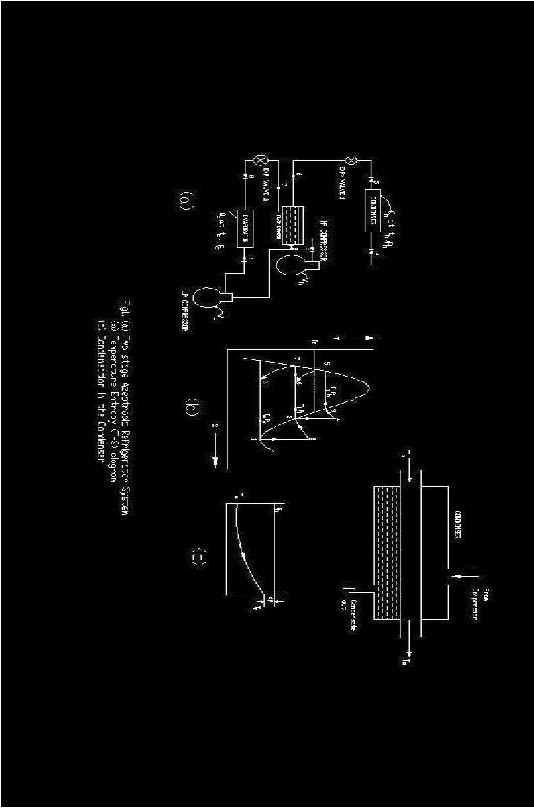
Figure -1(a) shows the schematic of idealized two stage refrigeration system. The various heat and work quantities and pressure levels are indicated in the figure. The following simplifying assumptions are made for this system analysis:
a) The thermodynamic cycle of the system is a standard one comprising isentropic compression, isentropic expansion and absence of superheating of the suction vapour and sub cooling of the high pressure (HP) condensate.
b) The pressure drop in evaporator, compressor valves, condenser piping etc are neglected.
c) Entire condensation of HP gas inside the condenser takes place at a fixed temperature (Th).
IJSER © 2011 http://www.ijser.org
International Journal of Scientific & Engineering Research, Volume 2, Issue 6, June-2011 3
ISSN 2229-5518
IJSER©2011 http:I!\Miwv.ijser.orq
International Journal of Scientific & Engineering Research, Volume 2, Issue 6, June-2011 4
ISSN 2229-5518
Referring to fig-1(b), one may write refrigerant mass flow through LP compressor on per ton-hour basis as :
M1 = 12,600/(h1 –h5 ) ----------5.1
By energy balance on the flash chamber, refrigerant mass flow through HP compressor turns out to be : M3 = M1 ( h2 –h1 ) /( ( h3 –h6 )
= 12,600( h2 –h1 ) / (h1 –h5 ) (h –h5 ) -----------5.2a
If we consider that refrigerant mass flow through LP compressor is unit kg, then mass flow through HP compressor based on similar lines, would be :
M3 = ( h2 –h1 ) /( ( h3 –h6 ) -----------5.2b and, total compression work shall be :
WT = ( h2 –h1 ) + M3 ( ( h4 –h3 ) -----------5.3a
However, on the basis of per ton hour, the total compression work may be written as : W =W1 + W2
= M1 ( h2 –h1 ) + M1 ( h4 –h3 ) --------------5.3b
Power consumption of the system :
P = W/(3600) --------------5.4
For preliminary design purposes, the enthalpies per unit mass of superheated vapour at points 2 and 4 can be approximately related to the enthalpies per unit mass of the saturated vapours at points 3 and 4, respectively as:
h2= h3 + Ti ( s1-s3 ) --------------5.5 h4= h9 + Th ( s3-s9 ) --------------5.6
saturated properties of both the azeotropes are estimated from the correlations available in reference (10) The coefficient of performance of system shall be :
COP = Qc / W = 12,600/ W --------------5.7
Economic water rate expression as developed in ref (7,8) per unit ton of refrigeration, when total operating costs are minimized, is given by :
IJSER © 2011 http://www.ijser.org
International Journal of Scientific & Engineering Research, Volume 2, Issue 6, June-2011 5
ISSN 2229-5518
Mwe = 15.45 ( Qh .L1P .C/Cw)0.5 --------------5.8
When Qh is heat rejection to condenser per ton per hour and is given as : Qh = M3 (h4 - h5 ) --------------5.9
L1P is the increase in power ‘P’ per degree rise in condensing temperature. Optimum condensing temperature is expressed as :
Tho=Twi+DTo --------------5.10
Where DTo = 0.1545 ( Qh/ P . Cw/C)0.5 +AP -------------5.11
With AP as the approach, Fig 1(c) representing the end temperature difference.
It is evident that the expressions given in equation 5.4 and 5.7 to 5.9 can be expressed in temperature alone. An explicit expression has not been attempted at as it becomes extremely involved. Moreover, it serves no useful purpose because We can directly feed the above expressions in computer program to evaluate the objective function. The governing performance quantities in terms of operating parameters/variables can be expressed as:
P= P ( Ti,,Th, Te,Twi, AP, Qc) -------------5.12
L1P =P (Th +1, Ti, Te,Twi,,AP, Qc ) - P (Th,Ti,Te,Twi, AP, Qc) -------------5.13
Qh = Qh(Th , Ti, Te,Twi, AP, Qc ) -------------5.14
Mwe = Mwe (Th , Ti, Te,Twi, AP, Qc, c, cw ) -------------5.15
COP= (Th , Ti, Te,Twi, AP, Qc ) -------------5.16
5.2 System Employing Air Cooled Condenser ( Case-2)
All the assumptions as mentioned above are also valid for this case. Since System is not incorporating water cooled condenser, only power consumed by compressors needs to be minimized to minimize the total operating cost.It indirectly suggests that COP should be maximized. In equation 5.7, compression work (W) has been substituted from equation 5.3a. It has been established in ref.6 that COP is strongly dependent upon the inter-stage pressure/temperature besides other factors. Thus in order to achieve maximum COP, inter-stage pressure/temperature should be optimized. Equations 5.2 to 5.7 have
been used for this.
IJSER © 2011 http://www.ijser.org
International Journal of Scientific & Engineering Research, Volume 2, Issue 6, June-2011 6
ISSN 2229-5518
5.3 Objective Function and Optimization
For case 1, the objective function is the total operating cost together with the COP as given by equations (5.15) and ( 5.16)
above. The total operating costs are to be minimized producing maximum COP as well.Since total operating costs
have been minimized while deriving expressions for economic water rate ( @we).from equations 5.15 and 5.16, it is clear that @we and COP depend upon inter-stage and condensing temperatures ( Ti and Th ) if other parameters are kept fixed. It leads to a two dimensional maximization problem with the two decision variables ( Ti and Th ) subject to the
constraints:
Te < Ti < Th -------------5.17
And
Th > Twi + AP ------------5.18
For case -2 the objective function is the coefficient of performance as given by ( 5.7) but in this equation (W) has been calculated from equation (5.3a). There is only one decision variable ( Inter-stage pressure/temperature) and hence would be a one dimentional maximization problem subjected to the constraint as given by equation (5.17) only.
5.4 Solution Technique
To find Tho, where total operating cost is minimum together with the optimum system performance, initially some convenient Th >Ta was assumed. With the help of this Th and given values of evaporator temperature(Te ) subroutine maximises the COP and transfers required optimum quantities (@3 and P) to the main program. Now Th is increased by unit degree and the above process is repeated. P is determined. Qh is found from equation 5.9 in the main program. Thereafter, DTo is estimated from equation 5.11 to determine Tho from equation 5.10. With this new value of Tho, the above computations are repeated till two successive values of Tho differ by + 0.1% . Condensing temperature , thus predicted , is the required optimum condensing temperature ( Tho) because it produces minimum operating cost for maximum COP. Finally, at Tho , @we is determined from equation 5.8, Fig 1.2(a) and 1.2(b).
For case-2, only subroutine OPTIMUM is used. Different values of condensing and evaporating temperatures are fed to the sub-routine and inter-stage temperatures are optimized for maximum COP’s. Later at these optimal points, main design quantities are computed and are termed as the optimum design quantities as they yield maximum COP of the system or minimum operating cost. Method of successive iterations has been used to optimize the systems for both the cases. During computation, the necessary properties of the liquid and gaseous azeotropes have been found from the co-relations given in ref (9).
Different ranges of various operating parameters considered for the azeotropic systems are based upon practical considerations and their commonly adopted values. They are as follows:
Evaporator temperature : 5 t0 -50@
Ambient/Cooling Water Temperature : 15 to 75@ Approach Temperature : 2 to 5@ Cost ratio : 0.5 to 10
IJSER © 2011 http://www.ijser.org
International Journal of Scientific & Engineering Research, Volume 2, Issue 6, June-2011 7
ISSN 2229-5518
6.1 SYSTEM WITH WATER COOLED CONDENSER:
Besides the direct use of Tables 6-1 to 6-3 for preliminary optimum design of the systems, they also exhibit the quantitative effects of operating variables on the design quantities for a specified set of operating parameters. Not only this, the feasible operating conditions can also be achieved with the help of the figures achieved. The graphical presentation of thermodynamic performance, display of main optimum design quantities for R-500 and R-502 respectively when the systems have been optimized for COP’s only over a quite wide range of operating temperature limits is under the scope of future work..
The approach (AP) has been kept at 3@. For a fixed set of Rc, AP, ta and te values, tho for R-500 is found to be slightly higher than that of R-502. On the other hand, economic water rate and heat rejection to condenser Qho are seen to be higher in case of R-502 for given Rc (except equal to 10) ,AP, ta and te refer Tables 6.1 to 6.3. the detailed graphical presentation is under the scope of future research.
6.2 SYSTEM WITH AIR COOLED CONDENSER
Tables 6-4 to 6-5 can be directly used for preliminary design for preliminary optimum design of the systems operating on R-
500 and R-502 using air Cooled Condenser. They also exhibit the quantitative effects of operating variables on the design quantities for a specified set of operating parameters. Not only this, the feasible operating conditions can also be achieved with the help of the figures achieved. The graphical presentation of thermodynamic performance, display of main optimum design quantities for R-500 and R-502 respectively when the systems have been optimized for COP’s only over a quite wide range of operating temperature limits, is under the scope of future research.
COP’s of R-500 system is observed to be higher than that of R-502 systems ( Ref. Tables 6.4 and 6.5)
IJSER © 2011 http://www.ijser.org
International Journal of Scientific & Engineering Research, Volume 2, Issue 6, June-2011 8
ISSN 2229-5518
Design Parameters : Rc = 3.0 AP = 3c
Azeotrope | R-502 | R-500 | ||||||||
te (c) | tio (c) | tho (c) | Mwe (Kg/ton- h) | Qho (KJ/ton-h) | COPo | tio (c) | tho (c) | Mwe (Kg/ton- h) | Qho (Kg/ton-h) | COPo |
-50 -40 -30 -20 | -7.66 -3.01 1.73 6.55 | 30.34 30.53 30.73 30.93 | 595.01 547.61 506.17 469.5 | 18,289.2 17,280.1 16,392.8 15,602.9 | 2.21 2.69 3.32 4.20 | -12.25 -3.38 1.46 6.27 | 31.13 30.95 31.11 31.27 | 527.79 512.50 477.37 446.45 | 18096.5 17067.8 16215.0 15462.3 | 2.29 2.82 3.49 4.40 |
-50 -40 -30 -20 | 4.12 8.55 13.06 17.56 | 49.72 49.92 50.12 50.33 | 725.90 662.23 606.87 558.34 | 20,435.5 19,193.4 18,106.1 17,143.3 | 1.61 1.91 2.29 2.77 | 2.91 7.43 12.28 16.95 | 49.94 50.8 50.22 50.36 | 680.87 628.80 583.64 544.00 | 19808.5 18663.4 17663.9 16784.4 | 1.75 2.08 2.49 3.01 |
-50 -40 -30 -20 | 16.17 20.27 24.45 28.71 | 69.13 69.32 69.51 69.71 | 911.86 824.51 749.28 683.87 | 23,414.2 21,817.0 20,429.9 19,210.3 | 1.17 1.37 1.614 1.91 | 15.10 19.69 24.27 28.81 | 69.32 69.47 69.63 69.79 | 831.87 761.94 700.83 647.39 | 22028.1 20659.7 19458.9 18404.9 | 1.34 1.56 1.84 2.17 |
IJSER © 2011 http://www.ijser.org
International Journal of Scientific & Engineering Research, Volume 2, Issue 6, June-2011 9
ISSN 2229-5518
Design Parameters : Rc = 3.0 ta = 30c
Azeotrope | R-502 | R-500 | ||||||||
te (c) | tio (c) | tho (c) | Mwe (Kg/ton- h) | Qho (KJ/ton-h) | COPo | tio (c) | tho (c) | Mwe (Kg/ton-h) | Qho Kg/ton- h) | COPo |
-50 -40 -30 -20 | -2.44 2.10 6.72 11.43 | 39.10 39.30 39.50 39.71 | 645.29 591.51 544.63 503.26 | 19,184.6 18,081.3 17,113.0 16,252.9 | 1.91 2.30 2.79 3.45 | 2.57 2.02 6.83 11.63 | 40.29 40.57 40.74 40.91 | 527.79 512.50 477.37 446.45 | 18096.5 17067.8 16215.0 15462.3 | 2.01 2.42 2.94 3.63 |
-50 -40 -30 -20 | -1.32 3.34 7.87 12.50 | 41.03 41.23 41.44 41.65 | 658.27 602.83 554.58 512.05 | 19,397.3 18,271.2 17,283.0 16,405.7 | 1.85 2.22 2.69 3.31 | -1.82 2.86 2.69 3.31 | 41.90 42.09 42.23 42.39 | 680.87 628.80 583.64 544.00 | 19808.5 18663.4 17663.9 16784.4 | 1.97 2.37 2.88 3.54 |
-50 -40 -30 -20 | -0.71 3.86 8.50 13.03 | 42.0 42.20 42.41 42.62 | 665.00 608.76 559.74 516.64 | 19,505.8 18,367.9 17,359.5 16,483.5 | 1.82 2.18 2.64 3.24 | -1.41 3.30 8.14 12.85 | 42.72 42.89 43.03 42.7 | 831.87 761.94 700.83 647.39 | 22028.1 20659.7 19458.9 18404.9 | 1.95 2.34 2.84 3.49 |
IJSER © 2011 http://www.ijser.org
International Journal of Scientific & Engineering Research, Volume 2, Issue 6, June-2011 10
ISSN 2229-5518
Design Parameters : AP= 3.0(c) ta = 30c
Azeotrope | R-502 | R-500 | ||||||||
te (c) | tio (c) | tho (c) | Mwe (Kg/ton- h) | Qho (KJ/ton-h) | COPo | tio (c) | tho (c) | Mwe (Kg/ton- h) | Qho (Kg/ton-h) | COPo |
-50 -40 -30 -20 | 3.92 8.57 13.2 17.82 | 49.48 49.94 50.41 50.89 | 295.59 270.49 248.71 229.41 | 20,407.2 19,198.4 18,138.0 17,196.7 | 1.61 1.91 2.28 2.74 | 2.90 7.54 12.43 17.29 | 50.013 50.34 50.67 51.01 | 277.90 257.40 239.05 223.10 | 19,806.0 18,677.5 17,698.2 16,832.8 | 1.75 2.07 2.47 2.98 |
-50 -40 -30 -20 | -2.78 1.73 6.42 11.00 | 38.51 38.67 38.83 38.99 | 828.24 759.07 698.75 645.65 | 19,121.7 18,020.7 17,054.8 16,196.9 | 1.93 2.32 2.83 3.50 | -2.96 1.62 6.42 11.2 | 39.62 39.87 40.02 40.17 | 679.22 617.21 572.77 534.11 | 18,832.1 17,765.7 16,843.3 16032.8 | 2.02 2.44 2.97 3.67 |
-50 -40 -30 -20 | -3.75 0.82 5.38 10.02 | 36.92 37.03 37.15 37.26 | 1153.26 1057.20 973.64 899.93 | 18,953.4 17,865.8 16,912.1 16,065.0 | 1.98 2.39 2.92 3.64 | -4.83 0.11 4.54 9.41 | 36.49 36.82 37.39 36.79 | 1271.04 1098.81 904.37 998.34 | 18,564.3 17,575.4 16,616.3 15,847.3 | 2.11 2.53 3.14 3.88 |
IJSER © 2011 http://www.ijser.org
International Journal of Scientific & Engineering Research, Volume 2, Issue 6, June-2011 11
ISSN 2229-5518
th (c) | te (c) | tio (c) | r1 | r2 | M3 (Kg/Kg) | V1 (m3/kg) | V3 (m3/kg) | WT (KJ/Kg) | COPo |
15 | -20 -30 -40 -50 | -2.22 -7.00 -12.20 -16.82 | 1.902 2.426 3.146 4.320 | 1.718 2.024 2.436 2.893 | 1.14 1.19 1.24 1.30 | 0.1123 0.1645 0.2484 0.3905 | 0.0695 0.846 0.1055 0.1297 | 26.14 35.56 46.25 58.23 | 6.71 4.93 3.79 3.01 |
30 | -20 -30 -40 -50 | 5.62 0.90 -3.84 -12.21 | 2.455 3.169 4.22 5.129 | 2.023 2.356 2.760 3.704 | 1.23 1.28 1.34 1.43 | 0.1123 0.1645 0.2484 0.3905 | 0.0584 0.0705 0.0858 0.1214 | 36.87 46.90 58.23 72.60 | 4.52 3.56 2.86 2.34 |
45 | -20 -30 -40 -50 | 14.00 9.33 4.65 -0.05 | 3.172 4.141 5.584 7.818 | 2.292 2.638 3.064 3.557 | 1.33 1.39 1.46 1.54 | 0.1123 0.1645 0.2484 0.3905 | 0.495 0.0594 0.0717 0.0873 | 46.76 57.41 69.47 83.07 | 3.36 2.74 2.26 1.89 |
60 | -20 -30 -40 -50 | 22.71 18.11 13.60 9.06 | 4.076 5.376 7.353 10.451 | 2.503 2.851 3.253 3.733 | 1.48 1.55 1.63 1.72 | 0.1123 0.1645 0.2484 0.3905 | 0.0429 0.0512 0.0613 0.0739 | 58.99 70.50 83.50 93.17 | 2.49 2.09 1.76 1.50 |
IJSER © 2011 http://www.ijser.org
International Journal of Scientific & Engineering Research, Volume 2, Issue 6, June-2011 12
ISSN 2229-5518
th (c) | te (c) | tio (c) | r1 | r2 | M3 (Kg/Kg) | V1 (m3/kg) | V3 (m3/kg) | WT (KJ/Kg) | COPo |
15 | -20 -30 -40 -50 | -2.02 -6.80 -11.60 -16.42 | 1.84 2.31 3.00 4.05 | 1.65 1.92 2.25 2.66 | 1.169 1.221 1.279 1.345 | 0.0611 0.0877 0.1302 0.2004 | 0.0396 0.0481 0.0588 0.0726 | 21.97 29.86 38.69 48.73 | 6.46 4.76 3.67 2.92 |
30 | -20 -30 -40 | 6.02 1.40 -3.42 -7.91 | 2.34 2.99 3.95 5.41 | 1.84 2.12 2.44 2.84 | 1.278 1.339 1.404 1.481 | 0. 0611 0.0877 0.1302 0.2004 | 0.0340 0.0408 0.0494 0.0604 | 30.91 39.31 48.74 59.49 | 4.29 3.37 2.72 2.23 |
45 | -20 -30 -40 -50 | 14.40 10.03 5.55 1.15 | 2.98 3.86 5.17 7.21 | 2.04 2.30 2.62 2.99 | 1.431 1.499 1.577 1.667 | 0. 0611 0.0877 0.1302 0.2004 | 0.0299 0.0355 0.0425 0.0513 | 39.68 48.64 58.74 70.24 | 3.09 2.52 2.08 1.74 |
60 | -20 -30 -40 -50 | 23.21 18.91 14.70 10.56 | 3.77 4.94 6.71 9.52 | 2.19 2.45 2.75 3.09 | 1.652 1.736 1.830 1.938 | 0. 0611 0.0877 0.1302 0.2004 | 0.0267 0.0318 0.0379 0.0452 | 48.76 58.47 69.34 81.74 | 2.29 2.91 1.61 1.36 |
IJSER © 2011 http://www.ijser.org
International Journal of Scientific & Engineering Research, Volume 2, Issue 6, June-2011 13
ISSN 2229-5518
1.For a preliminary design of two stage azeotropic refrigerating system, the Tables 6-1 to 6-5 presented can directly be used.
2. Economic water rate and heat transfer to condenser turns out to be relatively lower in case of R-500 for a given set of condenser, evaporator, ambient and approach temperatures and cost ratio.
3. R-500 system produces comparatively higher COP than R-502 system for specified operating conditions.
4.The effect of approach temperature is more pronounced on the economic water rate than the other quantities. It should be selected quite carefully.
5.Though, the initial investment in case of R-500 system turns out to be more than R-502 system, it would get compensated over a small span of time because of lower operating cost of the R-500 system.
IJSER © 2011 http://www.ijser.org
International Journal of Scientific & Engineering Research, Volume 2, Issue 6, June-2011 14
ISSN 2229-5518
1. Buchler,Leon, Economical use of condense water for Amonia Compression refrireration systems, Ice and Refrig, January,1947.
2. Bochmer,Andrew P., Condenser pressure for Air Conditioning,Heating,Piping and air-Cond., p77 and 94,1946.
3. Buchler,Leon, Andrew P., economical of condenser water in compression refrigeration system, journal ASRE,
57,pp. 251-254 March,1949.
4.Mcharness,R.C. and chapman, D.D., Refrigerating capacity and performance data,ASRE J., pp 49-58, January,1962.
5.Downing,R.C. Mixed refrigerants, Service Manual RT-38, EI. Du Pont Nemours company., Wilmington, Delaware
U.S.A.
6. Gupta, V.K and Prasad, Manohar, Numerical Estimation of main parameters for realistic Two stage ammonia refrigerating systems, J. Indian Innstitute of Science Bangalore,64,10,pp.219-227,1983.
7. Jordan ,R.C. and Priester, G.B.refrigeration and Air conditioning, Prentice-Hall of India, New delhi,1969.
8. Prasad, Manohar, Refrigeration and air Conditioning, Wiley Eastern, New Delhi,1983.
9.Gupta, V.K., Thermodynamic design data for optimum performance of Two Stage Azeotropic Refrigerating systems, J.Heat Recovery Systems (U.K)
10. Kern,D.Q., Process Heat Transfer, Mv Graw-Hill, Kogakusha, Tokyo,1960.
11.Mahindru, D.V., Economic Water rate and Optimum Performance of Two Stage Azeotropic Refrigerating Systems, a Thesis submitted to Kanpur University in partial fulfillment of the requirements for the degree of Master of Technology, Mechanical Engineering (Design) ,1985.
AP : Approachc
C : Cost of Electricity (Rs/kw-h)
cw : Cost of Water (Rs/k- litre)
COPo: Maximum co-efficient of performance.
hx : Enthalpy per unit mass at state condition ‘ x’ ( kJ/kg)
M1 : Refrigerant mass flow through LP compressor 9kg/ton-h).
M3 : Refrigerant mass flow through HP compressor (kg/ton-h)
Mwe :Economic water rate ( kg/ton-h)
M3 : Refrigerant mass flow through HP compressor per unit mass
flow through Lp compressor( kg/kg).
P : Power 9kw/ton)
Po : Minimum power (kw/ton)
�P : Power increase per ton per degree rise in condensing
Temperature ( kw/ton-c)
IJSER © 2011 http://www.ijser.org
International Journal of Scientific & Engineering Research, Volume 2, Issue 6, June-2011 15
ISSN 2229-5518
Ph : Condensing pressure (bar)
Pe : Evaporating pressure (bar).
Pio : Optimum inter-stage pressure (bar).
Qh : Heat transfer to condenser ( kJ/ton-h).
Qho : Heat transfer to condenser pertaining to minimum operating cost and maximum COP (kJ/ton-h)
Qc : cooling effect per unit mass flow through LP compressor
(kJ/kg).
r1 : Compression ratio (Pio/Pe) of LP compressor. r2 : Compression ratio (Ph/Pio) of HP compressor. Rc : Cost ratio (c/cw).
sx :Entropy per unit mass at state condition ( kJ/kg-k)
ta, Ta : Ambient temperature (c,K)
tw1,Tw1: Inlet water temperature (c,K)
th, Th : condensing temperature (c,K)
te, Te :evaporating temperature (c,K).
tho,Tho : Optimum condensing temperature(c,K).
ti, Ti : Interstage temperatures (c,K)
to,To : Outlet water temperature (c,K)
tio,Tio : Optimum interstage temperature(c,K).
V1 : Minimum volume flow through LP compressor per unit mass flow through LP compressor (m3/kg).
V3 : Minimum volume through HP compressor per unit mass flow through LP compressor (m3/kg).
W1 : compression work of LP compressor (kJ/ton-h). W2 : compression work of HP compressor(kJ/ton-h). W : Total compression work (kJ/ton-h).
WT : Total compression work (kJ/ton-h).
IJSER © 2011 http://www.ijser.org