International Journal of Scientific & Engineering Research, Volume 4, Issue 12, December-2013 951
ISSN 2229-5518
Taljeet Singhˡ , Dr. A.S. Shahi² , Mandeep kaur³
Abstract-In view of the challenges encountered during welding of thick plates of AISI 304 SS grade it was decided to undertake the present work where the effect of multipass welding on various mechanical properties of 16mm thick plates have been studied. The main objective of this work was to investigate how different levels of welding arc energy affect the microstructure of the weld metal and the HAZ under different welding conditions and consequently, how the mechanical properties viz. transverse tensile strength, ductility and impact toughness of the weld joints were affected. The fabricated joints were subjected to radiographic testing so as to make a fair assessment about the quality of the joints.
The results obtained show that the low heat input during welding of AISI 304 SS is beneficial in achieving better tensile properties as compared to using high heat input. The impact properties show that impact value increased with increase
in welding heat input. It was found that the joints exhibited poorer impact value than the corresponding base material which is evident from the values obtained. It was further found that the microhardness possessed by the HAZ of the joints welded using low heat input (9 pass) combination was found to be higher than the HAZ of the joints welded using high heat input (7 pass) combination. This indicates that grain coarsening in the HAZ of the weld joints was more at high heat input.
The microstructural studies further have shown that at low heat input due to high cooling rate fine grain dendritic structure was obtained in the weld metal where as at high heat input relatively coarse grain interdendritic structure was
prevalent.
This work in the present form has helped in establishing a correlation between the microstructure and the mechanical properties and proves to be useful as a welding procedure database for the fabrication industry using thick sections of AISI 304
SS grades.
Key words- AISI 304 SS, SMAW process, Transverse tensile testing, Impact testing (Charpy V-notch testing), Bend testing, W eld zone, HAZ, Microhardness, Microstructure
—————————— ——————————
failure mode of the weld material after it was
loaded statically and cyclically [4].
Out of 300 series grade of steels type 304 SS is
extensively used in industries due to its superior low temperature toughness and corrosion resistance. One of the typical applications of type
304 SS include storing and transportation of
liquefied natural gas (LNG), whose boiling point
is -162°C under 1 atmosphere [3]. Additionally, for the industrial applications of the AISI 304 stainless steels, the welding method is widely used due to its simple assembly and/or joins on sheets, plates and/or pipes made out of this material. On the other hand, it is also imperative to highlight that during welding many discontinuities are produced, which acts as stress raisers that can lead to a decrease in the life of the weld. Therefore, the problems of this joining method have become an important issue of study in manufacture. Researchers studied the properties of the ASS, focused in correlating the microstructure at the joints (fusion zone, heat affected zone) of an SMAW process with the
Plates of different thicknesses are used for the fabrication of components, depending upon the applications. In most of the applications, the plates are welded by using multipass welding methods. The temperature distribution that occurs during multipass welding affects the material microstructure, hardness, mechanical properties and the residual stresses that will be present in the material after cooling to room temperature. A limited experimental data is available in the literature wherein the effect of multipass welding is studied on AISI304 stainless steel. Few reports regarding temperature distribution during multipass welding of plates is available in the literature [5]. In the present study, experimental work on the effect of multipass welding on the mechanical properties of 16mm thick AISI304 stainless steel joints has been undertaken.
IJSER © 2013 http://www.ijser.orgs
International Journal of Scientific & Engineering Research, Volume 4, Issue 12, December-2013 952
ISSN 2229-5518
Butt welded joints were made using double V-groove design and welding was
accomplished with SMAW (Shielded metal arc welding process) using 9 weld passes including root pass that required low heat input and 7 weld passes including root pass that required high heat input. The aim of the present work was to study the effect of multipass welding via inducing low and high heat input welding combination selected from the operational domain of the welding process. The fabricated joints were subjected to radiographic testing so as to make a fair assessment about the quality of the joints. The welded specimens were then subjected to transverse tensile testing and Charpy impact testing as per the standards ASTM E-08 and ASTM E-23 respectively.
————————————————
• Taljeet singh having masters degree program in welding and fabrication from SLIET, deemed-University, longowal, sangrur, India, PH-9464507205. E-mail: chahaltaljeet@gmail.com
• Dr. A.S. shahi, Associate professor in mechanical department in SLIET deemed university, longowal, sangrur, India, PH-
9872426789, E-mail: asshahi@yahoo.co.in
• Mandeep kaur having masters degree program in welding
TABLE 2
Chemical composition of 308l electrode, wt. %
Elem ents | C | Si | M n | P | S | Cr | N i | Fe |
%wei ght | 0. 03 | 0. 43 | 1. 65 | 0.0 21 | 0. 02 | 19. 70 | 9. 30 | Bala nce |
It is a well established fact that among all the welding variables in arc welding processes welding current is the most influential variable since it affects the current density and thus the melting rate of the filler as well as the base material. So in accordance with this fundamental fact two different heat input combinations corresponding to different welding currents, i.e.
low heat input and high heat input combinations
IJSER
and fabrication from SLIET, deemed-University, longowal,
sangrur, India, PH-8740911022. E-mail:
The base material used in the present investigation was in the form of AISI 304 SS plates of sizes 350x200x16 mm which were cut from a rolled sheet and the coated electrodes of
2.5mm and 3.15mm diameter of grade 308L were
used for the work. Table 1 & 2 shows the chemical composition of the base and the filler used.
TABLE 1
Chemical composition of aisi 304 stainless steel,
% weight
were selected for the present study. The butt
welded joints were fabricated using a low
current combination of range 15A and high
current combination of range 25A. The two plates to be welded were tacked together at both ends before commencing welding with a uniform gap of 2.5 mm between the plates, as in the general practice in industrial fabrication. The tacking weld arrangement was given to the plates to minimize the effect of shrinkage and distortion. In this arrangement, most parts of the top and bottom surface areas of the weld pad were exposed to ambient conditions and the welding was carried out in a down-hand position. The dimensional details of plates used in the experiments are shown in Fig.3.
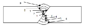
Multipass welding was carried out by an experienced welding operator. AWS 308L electrodes of size 2.50mm and 3.15mm were used to weld 304 stainless steel plates. The electrodes were baked in the oven for 45 min before welding to remove moisture. The numbers of passes taken for low heat input welding were 9 and during high heat input welding were 7 respectively. The weld bead sequence followed in these weld pads during the experimental work is shown in Fig.1 (a) & (b).
IJSER © 2013 http://www.ijser.orgs
International Journal of Scientific & Engineering Research, Volume 4, Issue 12, December-2013 953
ISSN 2229-5518
Figure 1 (a) W eld bead sequence in 16mm low heat input welded plates
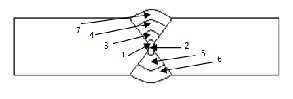
Figure 1 (b) W eld bead sequence in 16mm high heat input welded plates
In actual multipass welding, after a weld pass is laid, the weld plate is allowed to cool
down at an interpass temperature of 175-200° C
before the start of the next pass. In the present
work, the average time gap of 2 minute was given between the successive passes. This duration was utilized to remove the slag formed during each pass. During and after welding, the plates were visually inspected for their quality and it was ensured that both the weld beads possessed good geometrical consistency and were free from visible defects like surface porosity, blow holes etc. Fig. 2 shows the plates in the as welded condition using different heat inputs.
Considering an arc efficiency (η) of 0.75 for SMAW, the heat input per mm length of weld (Q) was calculated using the relation Q = ηVI/v, and these values are also shown in Tables 3 and
4.
Low heat high heat
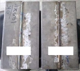
Figure 2. Photograph showing the base plates in the as welded condition at different heat inputs
TABLE 3
Experimental conditions (process parameters used for 9 pass welds)
Sr. no. Side (A) , (B) | Weld pass no. Ref. Fig.1(a) | Electrode size (mm) | Current (Amp) | Voltage (V) | Speed (mm/sec) | Heat Input (kJ/mm) |
1. (A) | Root pass | 2.5 | 87.5 | 21 | 2.845 | 0.484 |
2.(A) | 2nd pass | 2.5 | 92.5 | 22 | 3.723 | 0.409 |
3.(B) | Root pass | 2.5 | 87.5 | 21 | 3.301 | 0.417 |
4.(B) | 2nd pass | 2.5 | 92.5 | 22 | 2.592 | 0.588 |
5.(B) | 3rd pass | 2.5 | 92.5 | 22 | 2.160 | 0.706 |
6.(B) | 4th pass | 2.5 | 92.5 | 22 | 2.083 | 0.732 |
7.(A) | 3rd pass | 2.5 | 90 | 21 | 2.892 | 0.490 |
8.(A) | 4th pass | 2.5 | 95 | 22 | 2.348 | 0.667 |
9.(A) | 5th pass | 2.5 | 100 | 22 | 2.5 | 0.660 |
IJSER © 2013 http://www.ijser.orgs
International Journal of Scientific & Engineering Research, Volume 4, Issue 12, December-2013 954
ISSN 2229-5518
TABLE 4
Experimental conditions (process parameters used for 7 pass welds)
Sr. No. Side (A), (B) | Weld pass no. Ref. Fig.1(b) | Electrode size (mm) | Current (Amp) | Voltage (V) | Speed (mm/sec) | Heat Input (kJ/mm) |
1.(A) | Root pass | 2.5 | 82.5 | 21 | 1.767 | 0.735 |
2.(B) | Root pass | 3.15 | 112.5 | 23 | 3.153 | 0.615 |
3.(A) | 2nd pass | 3.15 | 117.5 | 23 | 2.095 | 0.735 |
4.(A) | 3rd pass | 3.15 | 132.5 | 24 | 1.989 | 1.199 |
5.(B) | 2nd pass | 3.15 | 125 | 23 | 2.272 | 0.949 |
6.(B) | 3rd pass | 2.5 | 112.5 | 23 | 2.272 | 0.854 |
7.(A) | 4th pass | 2.5 | 117.5 | 23 | 1.988 | 1.019 |
To understand any type of defects or discontinuities such as cracks, inclusions and porosity the radiography of the low and high heat input welded plates have been carried out. In radiography there are mainly three levels i.e. level 1, 2 and 3 which represent the quantity of
defects in the material. In the present study the defects were found at level 1, i.e. the slag inclusion and porosity shows the minor effect on the welded plates. Table 5 shows the result of non-destructive testing on the welded joints of the AISI 304 stainless steel plates.
IJSTABLE5 R
X-ray radiography results
Type of defects | Slag inclusion | Porosity | Internal shrinkage | Crack | Hot tear | Insert | Molting |
Results obtained from plate 1 | Level-1 | Nil | Nil | Nil | Nil | Nil | Nil |
Results obtained from plate 2 | Nil | Level-1 | Nil | Nil | Nil | Nil | Nil |
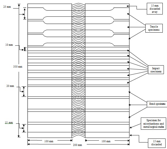
After conducting radiography on both the plates, specimens for tensile testing, bend testing,
impact testing, micro hardness testing and microstructural studies were taken from the weld pads as schematically illustrated in Fig. 3.
IJSER © 2013 http://www.ijser.orgs
International Journal of Scientific & Engineering Research, Volume 4, Issue 12, December-2013 955
ISSN 2229-5518
IJSER
Figure 3. Schematic diagram showing the specimen sampling plan from the butt welded plates (Top view)
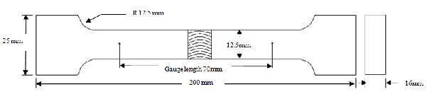
Three specimens per heat input combinations were machined out from the weld pads as mentioned in Fig.3. Each tensile specimen size was prepared in accordance with ASTM E08 standards as illustrated schematically in Fig.4. The specimens were tested on a servo hydraulically controlled digital tensile testing machine.
Six specimens per heat input combination were machined out from the weld pads as mentioned in Fig.3 and were prepared in accordance with
ASTM E-23 standards. Impact specimens were made with a V-notch in a weld metal zone and HAZ so as to make an assessment of their toughness. The angle of V-notch is 450.The standard impact specimen size is shown in Fig.5. The charpy V-notch values indicating the impact energy absorption by each of the welded specimens were recorded.
Three specimens per heat input combinations were taken from each welded plate as mentioned in Fig.3. Each bend test specimen size was prepared as illustrated schematically in Fig.6.
IJSER © 2013 http://www.ijser.orgs
International Journal of Scientific & Engineering Research, Volume 4, Issue 12, December-2013 956
ISSN 2229-5518
Figure 4. Schematic showing dimensions of tensile specimen used in the present work
Figure 4.5 Standard impact test specimen size
SEgrit up to 30R00 and polished by using a velvet
Figure 6. Schematic of the bend test specimen used in the present work
In the present work microhardness measurements were carried out on each welded plates. For microhardness testing the specimens were prepared using standard procedures like belt grinding, polishing using successively fine grades of emery up to 3000 grit size. This helped in removing coarse and fine oxide layers as well as scratches from the surface that were to be metallographically analysed. Microhardness tester (Make:Omnitech, Capacity:1000grams) was used to measure microhardness of base metal, weld zone and heat affected zone of the weldments using a load of 0.5 kg and a dwell time of 20 seconds.
In order to observe the micro structural changes that take place during welding, corresponding to each heat input combination specimens were machined out from the weld pads as shown in Fig.3. The surface to be investigated is subsequently ground using SiC paper down to
cloth. Standard polishing procedures were used for general micro structural observations. The specimens were electrolytically etched using the
following conditions:-
Electrolyte used: Oxalic acid (10 g) + Distilled water (100 ml), Cell voltage: 6 V, Etching time: 1 min
Tensile testing results obtained from this study show that the average UTS value is 591.84MPa for base metal, 661.41MPa for the low heat input (9 pass) combination and 565.36MPa for high heat input (7 pass) combination. It was observed that for the weld joints using low heat condition the UTS value is increased by 17%. Ductility, which was measured in the form of percentage elongation, was also increased for low heat input combination. Similar results were found for yield strength and percentage reduction in area for
IJSER © 2013 http://www.ijser.orgs
International Journal of Scientific & Engineering Research, Volume 4, Issue 12, December-2013 957
ISSN 2229-5518
low heat input welded plates. The yield strength shows the average increase of 9.1% for low heat
combination. Similarly the percentage reduction in area for low heat input (53.48) is much greater than that of high heat input (24.54) combination.
Further it is found that all the joints with low heat fractured in the base metal during tensile testing which indicates that weld metal in all the joints possessed higher tensile strength than the base metal whereas all the joints with high heat fractured in the weld zone during tensile testing which indicates that base metal possessed higher tensile strength than the weld metal. The fractured features of tensile tested specimens are shown in Fig.7.
It is found that impact value increase with increase in welding current. The average impact value of base material is 198.5J, for low heat input it is 113.4J in weld zone and 126.2J in HAZ. Similarly it shows the impact value of 141.2J in
weld zone and 147J in HAZ of high current
higher impact energy absorption capacity than those welded using low heat input welding.
It was observed that low heat input welded samples have the higher ductility as compared to high heat input welded specimens. Similar results during tensile test has been found by performing the bend test, i.e. bending of the low current welded specimen shows more strength as compare to that of high current welded specimens. All the three high heat input welded specimens were found crack in their weld zone whereas there is no crack found in the low heat input welded specimens. Fig. 8 shows the fractured features of low and high heat input welded samples after the test.
The microhardness was checked for base metal, weld zone and heat affected zone of low and high heat input welded specimens. At every
place readings were taken. All the readings are
IJSER
welded specimens. It was also observed that the weld joints made by using high current showed
shown in Table 6. Average micro hardness of
base metal is 256 VHN.
TABLE 6
Micro hardness (VHN) results
Specimen name | Base metal | Weld zone | Heat affected zone |
Low heat input | 253-259 | 310-316 | 360-365 |
High heat input | 253-259 | 306-312 | 309-318 |
Figure 9 represents the variation of
micro hardness values obtained from the different sources such as base metal and as- welded condition. The hardness values of as- welded specimens were much greater than base metal. High hardness values were observed in the HAZ region of the both low and high heat input weldments.
From the above observation it can be easily concluded that at the low heat input welded joints the microhardness has become higher as compared to micro hardness values at
370
360
350
340
330
320
310
300
290
280
363
313
Low heat input
314
309
High heat input
Series 1
Series 2
high heat input welded joints. The main reason is that the cooling rate of low heat input welded specimen is relatively higher than the high heat input specimen and the microhardness is directly related to the cooling rate at that point. Higher the cooling rate will produce higher microhardness.
Figure 9. Line graph comparison of microhardness of as welded plates
Subodh[3] have reported similar trends while studying the effect of heat input on the mechanical properties of TIG welded 304 SS joints that the micro hardness follows an
IJSER © 2013 http://www.ijser.orgs
International Journal of Scientific & Engineering Research, Volume 4, Issue 12, December-2013 958
ISSN 2229-5518
increasing trend in the order of weld metal, HAZ, unaffected base metal and fusion
boundary for all the joints made at different heat inputs.
Optical micrographs showing the microstructures of weld zone, fusion boundary and HAZ for different heat input combinations are presented from Figs. 10–11. Microstructural studies have shown that at low heat input due to high cooling rate fine grain dendritic structure is obtained in the weld metal where as at high heat input relatively coarse grain inter dendritic structure is observed. Full penetration welds were obtained in both combinations of heat input. It is found that as heat input increases the
fusion areas of the joints also increase proportionately. The same trend is followed for
the HAZ area associated with each of these joints. Several Studies reported that the fusion zone and HAZ area increase with increase in heat input. It is observed from these optical micrographs that as heat input increases the dendrite size and inter-dendritic spacing in the weld metal also increase. This dendrite size variation can be attributed to the fact that at low heat input, cooling rate is relatively higher due to which steep thermal gradients are established in the weld metal, which in turn allows lesser time for the dendrites to grow, whereas at high heat input, cooling rate is slow which provides ample time for the dendrites to grow farther into the fusion zone.
IJSER
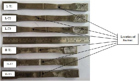
Figure 7. Transverse tensile tested specimens showing the location of fracture
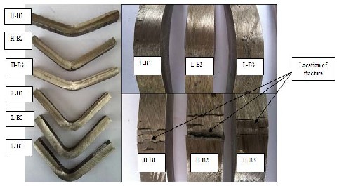
Figure 8. Bend tested specimens showing the location of fracture on low and high heat input welded joints
IJSER © 2013 http://www.ijser.orgs
International Journal of Scientific & Engineering Research, Volume 4, Issue 12, December-2013 959
ISSN 2229-5518
WM
FBZ
HAZ
0.14 mm
0.14 mm
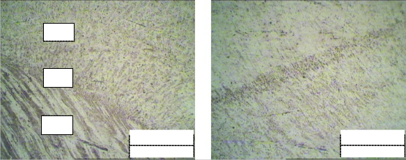
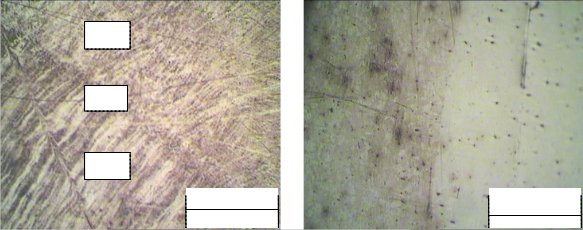
Figure 10. Optical micrograph (100X) showing the microstructure of (a) weld metal and HAZ (b) HAZ and base metal (low heat)
WM
FBZ
Figure 11. Optical mIicrograJph (100X) showSing the microstructuEre of (a) weld metalRand HAZ (b) HAZ and base metal (high
0.14 mm
0.14 mm
![]()
heat)
Based upon the work undertaken the following conclusions could be drawn:
• Joints welded with 9 weld passes including root pass using low heat input were found to possess better strength than those welded using 7 weld passes including root pass using high heat input. The maximum UTS was found to increase by 17% for the joints fabricated using low heat input (9 pass) combination. This shows that the low heat input weld joints is beneficial in achieving better tensile properties as compared to using high heat input weld joints.
• The bend testing results show that low
current welded specimens possessed greater strength as compared to those of high heat input welded specimens.
• The impact properties show that impact value increased with increase in welding heat input. It was found that the joints exhibited poorer impact value than the corresponding base material which is evident from the values obtained, as the average impact value possessed by the base material was 198.5J, for low heat input it was 113.4J in weld zone and
126.2J in HAZ. Similarly it showed the impact value of 141.2J in the weld zone and 147J in the HAZ of high heat input welded specimens.
• The microhardness possessed by the
HAZ of the joints welded using low heat input (9 pass) combination was found to be higher than the HAZ of the joints welded using high heat input (7 pass) combination. This indicates that grain coarsening in the HAZ was more at high heat input.
IJSER © 2013 http://www.ijser.orgs
International Journal of Scientific & Engineering Research, Volume 4, Issue 12, December-2013 960
ISSN 2229-5518
• Micro structural studies have shown that at low heat input due to high cooling rate fine grain dendritic structure was obtained in the weld metal where as at high heat input relatively coarse grain interdendritic structure was prevalent.
Based upon the present study it is concluded that for the multipass welding of AISI
304SS using SMAW process the low heat input should be preferred because of the reason that it gives good transverse tensile strength and ductility to the joints.
[1]. Andrés R. Galvis E, W. Hormaza “Characterization of failure modes for different welding processes of AISI/SAE 304 stainless steels” Engineering Failure Analysis, Volume
18, Issue 7, Pages 1791-1799, October 2011.
[2]. A.M. Huntz, A. Reckmanna, C. Haut, C.
Severac, M. Herbst, F.C.T. Resende, A.C.S. Sabioni “Oxidation of AISI 304 and AISI 439 stainless steels” Materials Science and Engineering A 447, Pages 266–276, 2007.
welded pipe” International Journal of Pressure
Vessels and Piping, Volume 84, Issue 5, Pages
298-303, May 2007.
[10]. Jun Yan, Ming Gao, Xiaoyan Zeng “Study on microstructure and mechanical properties of 304 stainless steel joints by TIG, laser and laser-TIG hybrid welding” Optics and Lasers in Engineering, Volume 48, Issue 4, Pages 512-517, April 2010.
[11]. Jong-Hyun Baek, Young-Pyo Kin, Woo-Sic Kim, Young-Tai Kho “Effect of Temperature on the Charpy Impact and CTOD values of type 304 stainless steel Pipeline for LNG Transmition” K S M E International jerenal, vol. 16 no.8, Pages
1064-1071, 2002.
[12]. J.A. Rodrıguez-Martınez, A.Rusinek, R.Pesci
“Experimental survey on the behaviour of AISI
304 steel sheets subjected to perforation” Thin- Walled Structures, Pages 966–978, 2010.
[13]. Jha Abhay K, Diwaker V, Sreekumar K “Metallurgical investigation on stainless steel bellows used in satellite launch vehicle” Eng Fail Anal, Pages 1437–47, 2006.
[14]. Khana, O.P “A textbook of Welding Technology” Pub: dhanpat rai pub. Ltd. New Delhi, India, 18th edition, 2007.
[15]. K. K. Raya, K. Duttab, S. Sivaprasadc, S.
Tarafderc “Fatigue damage of AISI 304 LN
IJSER
[3]. B-W. Cha, S-J. Na “A study on the relationship
between welding conditions and residual stress of resistance spot welded 304-type stainless steels” Journal of Manufacturing Systems, Volume 22, Issue 3, Pages 181-189, 2003.
[4]. B.K. Singh, Vakil Singh “Effect of fast neutron irradiation on tensile properties of AISI 304 stainless steel and alloy Ti–6Al–4V” Materials Science and Engineering A 528 (2011), Pages
5336–5340, 2011.
[5]. Barcellona A, Buffa G, Fratini L, Palmeri D “On microstructural phenomena occurring in friction stir welding of aluminium alloys” Journal of Materials Processing Technology. vol.177,Pages
340–343, 2006.
[6]. Baek Jong-Hyun, Kim Young-Pyo, Kim Woo- Sik, Young-Tai Kho “Fracture toughness and fatigue crack growth properties of the base metal and weld metal of a type 304 stainless steel pipeline for LNG transmission” Int J Pressure Vessels Pipe, Pages 351–367, 2001.
[7]. G Magudeeswaran', V Balasubramaniarr, G Madhusudhan, ReddyZ, T S Balasubrarnaniarr' “Effect of Welding Processes and Consumables on Tensile and Impact Properties of High Strength Quenched and Tempered Steel Joints” Journal of Iron and Steel Research, International, Pages 87-94, August 19, 2007
[8]. G. Bregliozzia, A. Di Schinob, J.M. Kennyb, H.
Haefke “The influence of atmospheric humidity and grain size on the friction and wear of AISI
304 austenitic stainless steel” Materials Science and Technology, Pages 4505– 4508, 2003.
[9]. Jijin Xu, Ligong Chen, Chunzhen Ni “Effect of vibratory weld conditioning on the residual stresses and distortion in multipass girth-butt
stainless steel: Role of mean stress” Procedia
Engineering 2, Pages 1805–1813, 2010.
[16]. Nadkarni, S.V. “Modern arc welding process”
4th Edition, Oxford & IBH publishing Co. Pvt. Ltd; New Delhi, India, 1988.
[17]. Parmar, R.S., “Welding processes and technology” 3rd Edition, Khanna publisher, New Delhi, India, 2006.
[18]. Ravindra Kumar, V.K. Tewari, Satya Prakash “Oxidation behavior of base metal, weld metal and HAZ regions of SMAW weldment in ASTM SA210 GrA1 steel” Journal of Alloys and Compounds 479, Pages 432–435, 2009.
[19]. S Murugan, P.V Kumar, B Raj, M.S.C Bose “Temperature distribution during multipass welding of plates” International Journal of Pressure Vessels and Piping, Volume 75, Issue
12, Pages 891-905, October 1998.
[20]. S Murugan, Sanjai K Rai, P.V Kumar, T Jayakumar, Baldev Raj, M.S.C Bose “Temperature distribution and residual stresses due to multipass welding in type 304 stainless steel and low carbon steel weld pads ” International Journal of Pressure Vessels and Piping, Volume 78, Issue 4, Pages 307-317, April
2001.
[21]. Subodh Kumar, A.S. Shahi “Effect of heat input on the microstructure and mechanical properties of gas tungsten arc welded AISI 304 stainless steel joints” Materials & Design, Volume 32, Pages 3617-3623, 2011.
[22]. WIKIPEDIA The free encyclopedia.
[23]. Yan Jun, Gao Ming, Zeng Xiaoyan “Study on microstructure and mechanical properties of 304 stainless steel joints by TIG, laser and laser-TIG
IJSER © 2013 http://www.ijser.orgs
International Journal of Scientific & Engineering Research, Volume 4, Issue 12, December-2013
ISSN 2229-5518
961
hybrid Welding" Opt Lasers Eng, Pages 512-7,
2010.
[24]. Zhibo Dong, Yanhong Wei, Yanli Xu
"Predicting weld solidification cracks in
multipass welds of SUS310 stainless steel" Computational Materials Science, Volume 38, Issue 2, Pages 459-466, December 2006.
IJSER © 2013