International Journal of Scientific & Engineering Research, Volume 5, Issue 7, July-2014 115
ISSN 2229-5518
Dual Feed Double patchy Broadband Microstrip
Antenna for
UHF Communication Applications
ABSTRACT : T hree s hort c irc uited microstrip patc h antenna s tructure with dual f eed has been propos ed with c onic al vi a. The des ign is based on rec tangular hole struc ture with c onic al vi a loading and s lit loading tec hnique. The s imulation is bas ed on method of moment method, using IE3D s oftware. It is als o obs erved that by c utting s lits of diff erent areas, the res on ating frequencies are getting c hanged along with bandwidth an d return loss. This antenna c an operate at GSM frequenc y, UHF c ommunic ation. and als o this antenna c an be applied for 30-300 GHZ applic ations .
A dual f eed wideband mic ros trip antenna has been propos ed. The design is bas ed on dual f eed tec hnique. In this pap er, the two patc hes at the either s ide ac ts as res istive elem ents to the main patc h in the middle. W e have obs erved that least the area of flowing of the current through the patc h, better the wideb and.
Key words: – Dual Feed, Three short circ uited Patc h, W ideband Micros trip Antenna, GSM Microstrip Antenna,
—————————— ——————————
1. INTRODUCTION
With the increase of the wireless communication systems we can notice the urge of future technologies are in need of low-profile antennas for wireless communications [1-2]. Because of many attractive features, microstrip antennas have received considerable attraction for mobile communication handset terminals.
There are several techniques to reduce the size of microstrip antennas at resonant frequencies. Using microwave substrate of high dielectric constant, patch dimension can be reduced, but the antenna shows poor efficiency due to surface wave generation. Edge-shorted patches using shorting wall or shorting plate can lower the physical dimensions of a microstrip patches. Further lowering of antenna dimension is possible using shorting pin at the proper position and by using shorting-pin loaded technique, antenna size reduction of about
89% can be achieved [3]. Also slot loaded patches are used to design small microstrip antennas.
The disadvantage of microstrip patch antenna is that it gives narrow bandwidth. However, researchers have made outstanding efforts to overcome this problem and configurations have been presented to increase the bandwidth.
In this paper we have designed a dual feed conical via loaded rectangular structure having three patches which gives a wideband at frequencies 710MHz to 1100MHz and 5.9GHz to 7.2GHz and narrowband at frequency 3.8GHz. We have taken the FR4 substrate which has dielectric constant as 4.4 and loss tangent 0.02 having substrate thickness 1.4mm.
2. INDENTATIONS AND EQUATIONS
We have a taken a rectangular microstrip antenna whose length was calculated depending on the dominant mode of operation i.e m=1 and n=0 from the equation given below.
IJSER © 2014 http://www.ijser.org
International Journal of Scientific & Engineering Research, Volume 5, Issue 7, July-2014 116
ISSN 2229-5518

The equations are [4]: For our design, Ɛe = 4.4 [FR4 Substrate]
The length and width of patch 1 and patch 2 = 10 mm
The length and width of patch 3 = 15 mm
we are able to get better return loss with wider bandwidth. And because of that the current path is getting directed in definite direction, thus showing us characteristics of wideband antenna. As well as the current well formed by the dual side rectangular patches.
3. FIGURES AND TABLES
We have proceeded from the basic patch to the slit cut-off final patch. The respective Figures show the path to our designed
antenna.
Figure 3.1- Shows the three rectangular patches proposed firstly.
Figure 3.2 - Shows the final structure with dual feed and conical via. (Here Conical via location is -7.5, -14.5 according to the axis taken.) Feed 1 is at location (-15,0) Feed 2 is at (0,0)
The Table 3.1 shows the best results we have found out from the carried out simulations. Simulations are done using IE3D [7]. Index: CVia Location= Conical Via Location
RF1= Resonating Frequency 1 (in MHz) RF2= Resonating Frequency 2 (in GHz) RF3= Resonating Frequency 3 (in GHz) RL1= Return Loss 1 (in dB)
RL2= Return Loss 2 (in dB)

IJSER © 2014 http://www.ijser.org
International Journal of Scientific & Engineering Research, Volume 5, Issue 7, July-2014
ISSN 2229-5518
:tvfHz
117
IJSER © 2014
http://www .'lser.org
International Journal of Scientific & Engineering Research, Volume 5, Issue 7, July-2014 118
ISSN 2229-5518

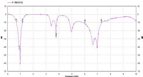 Figure 3.1: Return Loss Graph

 Figure 3.2: - Antenna Structure
IJSER © 2014 http://www.ijser.org
International Journal of Scientific & Engineering Research, Volume 5, Issue 7, July-2014 119
ISSN 2229-5518
.CONCLUSION: We have seen dual feed triple patch rectangular microstrip antenna resonating at multiple frequencies and also giving wide bandwidth in GSM range, WLAN frequency and C BAND. But it provides with low gain.
Our further study will follow the miniaturization of our antenna and obtaining better gain with almost fixed bandwidth i.e wide. We will study it using ground defected structure. We are trying to develop a small sized antenna for mobile terminals as well as WLAN applications
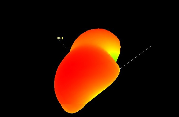
Figure 3.3 – 3D radiation pattern at 4.8GHz with -1dbi gain.
.
REFERENCES
[1] P.N. MISRA “PLANAR RECTANGULAR MICROSTRIP ANTENNA FOR DUALBAND OPERATION”
ISSN : 2229-4333 ( PRINT ) | ISSN :0976- 8491 IJCST VOL. 2, ISSUE 3, SEPTEMBER 2011.
[2] VIDHI SHARMA, DWEJENDRA ARYA “DUAL BAND MICROSTRIP PATCH ANTENNA USING DUAL FEED FOR WIRELESS APPLICATIONS” INTERNATIONAL JOURNAL OF ELECTRONICS AND COMPUTER SCIENCE ENGINEERING AT WWW.IJECSE.ORG ISSN: 2277-1956.
[3] WONG, K. L., COMPACT AND BROADBAND MICROSTRIP ANTENNAS, WILEY, 2002.
TECHNOLOGY, 2002.
[4] BALANIS C. A, “MICROSTRIP ANTENNAS”, ANTENNA THEORY, ANALYSIS AND DESIGN, THIRD EDITION, JOHN WILEY & SONS
[5] J.S.ROY, N.CHATTORAJ, N.SWAIN NEW-DUAL FREQUENCY MICROSTRIP ANRENNAS FOR WIRELESS COMMUNICATIONS ROMANIAN JOURNAL OF INFORMATION SCIENCE AND TECHNOLOGY, VOLUME 10, NUMBER 1,2007,113-119
IJSER © 2014 http://www.ijser.org
International Journal of Scientific & Engineering Research, Volume 5, Issue 7, July-2014 120
ISSN 2229-5518
[6] HANDBOOK OF MICROSTRIP ANTENNAS BY J R JJAMES AND P S HALL, IEEE EMWAVE SERIES 28, 1989.
AUTHOR
1. RAHUL CHOWDHURY
Pursuing B.Tech in Electronics AND COMMUNICATION from SWAMI VIVEKANANDA INSTITUTE OF SCIENCE AND TECHNOLOGY,WEST BENGAL UNIVERSITY OF TECHNOLOGY, 2014, WEST BENGAL,INDIA.
IJSER © 2014 http://www.ijser.org