International Journal of Scientific & Engineering Research, Volume 3, Issue 1, January-2012 1
ISSN 2229-5518
Digitally Greenhouse Monitoring and Controlling of System based on Embedded System
Kiran Sahu, Mrs. Susmita Ghosh Mazumdar
—————————— ——————————
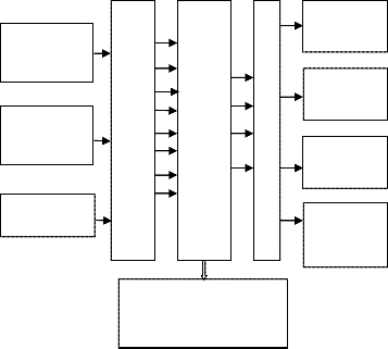
HE proposed system is an embedded system which will closely monitor and control the microclimatic parameters of a greenhouse on a regular basis round the clock for cultivation of crops or specific plant species which could maximize their production over the whole crop growth season and to eliminate the difficulties involved in the system by reducing human
M
Water
Pump
intervention to the best possible extent. The system
comprises of sensors, Analog to Digital Converter,
microcontroller and actuators [1].When any of the
above mentioned climatic parameters cross a safety
threshold which has to be maintained to protect the
crops, the sensors sense the change and the microcontroller reads this from the data at its input
ports after being converted to a digital form by the ADC [10]. The microcontroller then performs the needed actions by employing relays until the strayed-out parameter has been brought back to its optimum level. Since a microcontroller is used as the heart of the system, it makes the set-up low-cost and effective nevertheless. As the system also employs an LCD display for continuously alerting the user about the
Humidity
sensor
A
D Temperature
Sensor C
Light Sensor
I I N
C T Sprayer
E R R
F O
A Cooler
C C
E
O
Artificial
N Lights
condition inside the greenhouse, the entire set-up becomes user friendly. Thus, this system eliminates the drawbacks of the existing set-ups and is designed as an easy to maintain, flexible and low cost solution.
LCD (Display of Moisture, Humidity etc. & Actuator status)
————————————————
Mrs. Susmita ghosh mazumdar is a Reader in the Department of
Electronic & Tele Communication , R.C.E.T. Bhilai, and CSVTU, INDIA
Fig 1. Block Diagram of the System
IJSER © 2012 http://www.ijser.org
International Journal of Scientific & Engineering Research, Volume 3, Issue 1, January-2012 2
ISSN 2229-5518
• Sensors (Data acquisition system)
i. Temperature sensor ii. Humidity sensor
iii. Light sensor (LDR)
• Analog to Digital Converter
• Microcontroller (AT89C51)
• Liquid Crystal Display
• Actuators – Relays
• Devices controlled
i. Water Pump (simulated as a bulb)
ii. Sprayer (simulated as a bulb)
iii. Cooler (simulated as a fan)
iv. Artificial Lights (simulated as 2 bulbs)
Three general steps can be followed to appropriately select the control system:
Step # 1: Identify measurable variables important to production. It is very important to correctly identify the parameters that are going to be measured by the controller’s data acquisition interface, and how they are to be measured.
Step # 2: Investigate the control strategies.An important element in considering a control system is the control strategy that is to be followed. The simplest strategy is to use threshold sensors that directly affect actuation of devices.
Step # 3: Identify the software and the hardware to be used. Hardware must always follow the selection of software, with the hardware required being supported by the software selected. In addition to functional capabilities, the selection of the control hardware should include factors such as reliability, support, previous experiences with the equipment (successes and failures), and cost [2].
A transducer is a device which measures a physical quantity and converts it into a signal which can be read by an observer [9] .It can also be read by an instrument [3]. The sensors used in this system are:
1. Light Sensor (LDR (Light Dependent Resistor))
2. Humidity Sensor
3. Temperature Sensor
In physical world parameters such as temperature, pressure, humidity, and velocity are analog signals. A physical quantity is converted into electrical signals. We need an analog to digital converter (ADC), which is an electronic circuit that converts continuous signals into discrete form so that the microcontroller can read the data. Analog to digital converters are the most widely used devices for data acquisition [7].
Analog world | Transducer | Signal Conditioning | Analog to Digital Converter | Micro- controller |
Fig. 2 Getting data from the analog world
The microcontroller is the heart of the proposed embedded system [4]. It constantly monitors the digitized parameters of the various sensors and verifies them with the predefined threshold values [5]. It checks if any corrective action is to be taken for the condition at that instant of time. In case such a situation arises, it activates the actuators to perform a controlled operation [6].
A liquid crystal display (LCD) is a thin, flat display device made up of any number of color or monochrome pixels arrayed in front of a light source or reflector [4]. Each pixel consists of a column of liquid crystal molecules suspended between two transparent electrodes, and two polarizing filters, the axes of polarity of which are perpendicular to each other [6].
A relay is an electrical switch that opens and closes under the control of another electrical circuit. In the original form, the switch is operated by an electromagnet to open or close one or many sets of contacts. Because a relay is able to control an output circuit of higher power than the input circuit, it can be considered to be, in a broad sense, a form of an electrical amplifier.
The power supply section consists of step down transformers of 230V primary to 9V and 12V secondary voltages for the +5V and +12V power supplies respectively.
Keil Micro Vision is an integrated development environment used to create software to be run on embedded systems (like a microcontroller). It allows for such software to be written either in assembly or C programming languages and for that software to be
IJSER © 2012 http://www.ijser.org
International Journal of Scientific & Engineering Research, Volume 3, Issue 1, January-2012 3
ISSN 2229-5518
simulated on a computer before being loaded onto the microcontroller.
Tolerance = ±0.1V
TABLE 2
4.1.1 Device Database: A unique feature of the Keil
µVision3 IDE is the Device Database, which
contains information about more than 400 supported microcontrollers.
4.1.2 Peripheral Simulation: The µVision3 Debugger provides complete simulation for the CPU and on- chip peripherals of most embedded devices.
The programmer used is a powerful programmer for the Atmel 89 series of microcontrollers that includes
89C51/52/55, 89S51/52/55 and many more. Major parts of this programmer are Serial Port, Power Supply and Firmware microcontroller. Serial data is sent and received from 9 pin connector and converted to/from TTL logic/RS232 signal levels by MAX232 chip [8]. A Male to Female serial port cable, connects to the 9 pin connector of hardware and another side connects to back of computer.
ProLoad’ is a software working as a user friendly interface for programmer boards from Sunrom Technologies. The programmer connects to the computer’s serial port (Comm 1, 2, 3 or 4) with a standard DB9 Male to DB9 Female cable. Baud Rate - 57600, COMx Automatically selected by window software. No PC Card Required [5].
Readings taken at room temperature of 270C
TRANSDUCER’S READINGS
Tolerance= ± 0.2 V
LIGHT SENSOR READINGS
Illumination Status | Transducer Optimum Range |
OPTIMUM ILLUMINATION | 0V-0.69V |
DIM LIGHT | 0.7V-2.5V |
DARK | 2.5V- 3V |
NIGHT | 3V-3.47V |
RH = ((Vout / Vcc) – 0.16)/0.0062, typical at 25°C
where, Vsupply = 4.98V
TABLE 3
HUMIDITY SENSOR READINGS
TABLE 1
SOIL MOISTURE SENSOR READINGS
Soil Condition | Transducer Optimum Range |
Soil is dry | 0V |
Optimum level of soil moisture | 1.9- 3.5V |
Slurry soil | >3.5V |
IJSER © 2012 http://www.ijser.org
International Journal of Scientific & Engineering Research, Volume 3, Issue 1, January-2012 4
ISSN 2229-5518
FORMULA:
Temperature (0C) = (Vout/5) *100 (0C /V)
TABLE 4
TEMPERATURE SENSOR READINGS
Temperature range in degree Celsius | Temperature sensor output( Vout ) |
10 0C | 0.5V |
15 0 to 20 0C | 0.75-1.0V |
20 0 to 25 0 C | 1.0-1.25V |
25 0 to 30 0C | 1.25-1.5V |
30 0 to 35 0C | 1.5-1.75V |
350 to 40 0C | 1.75-2.0V |
40 0 to 45 0C | 2.0-2.25V |
45 0 to 50 0 C | 2.25-2.5V |
50 0 to 55 0C | 2.5-2.75V |
55 0 to 60 0C | 2.75-3.0V |
60 0 to 65 0C | 3.0-3.25V |
65 0 to 70 0C | 3.25-3.5V |
70 0 to 75 0C | 3.5-3.75V |
75 0 to 80 0C | 3.75-4.0V |
80 0 to 85 0C | 4.0-4.25V |
85 0 to 90 0C | 4.25-4.5V |
90 0 to 95 0C | 4.5-4.75V |
95 0 to 100 0C | 4.75-5V |
A step-by-step approach in designing the microcontroller based system for measurement and control of the four essential parameters for plant growth, i.e. temperature, humidity, soil moisture, and light intensity, has been followed. The results obtained from the measurement have shown that the system performance is quite reliable and accurate.
The system has successfully overcome quite a few shortcomings of the existing systems by reducing the power consumption, maintenance and complexity, at the same time providing a flexible and precise form of maintaining the environment.
The continuously decreasing costs of hardware and software, the wider acceptance of electronic systems
in agriculture, and an emerging agricultural control system industry in several areas of agricultural production, will result in reliable control systems that will address several aspects of quality and quantity of production. Further improvements will be made as less expensive and more reliable sensors are developed for use in agricultural production.
Although the enhancements mentioned in the
previous chapter may seem far in the future, the required
technology and components are available, many such systems have been independently developed, or are at least tested at a prototype level. Also, integration of all these technologies is not a daunting task and can be successfully carried out.
[1] Stipanicev D., Marasovic J.,‖ Network embedded greenhouse monitoring and control‖, Proceedings of 2003 IEEE Conference on Control Applications, Vol.2, June, pp. 1350 - 1355, 2003.
[2] Turnell, D.J. deFatima, Q.V., Turnell, M., Deep, G.S., Freire, R.C.S., ―Farm Web-an integrated, Modular farm automation system‖, Proceedings of IEEE International Conference on Systems, Man, and Cybernetics, Vol.2, Oct., pp. 1184 - 1189, 1998.
[3] Rebecca Tyson Northen, Orchids As House Plants, Dover Publications, New York, 2nd Edition, 1985.
[4] Muhammad Ali Mazidi, Janice Gillispie Mazidi, Rolin D. Mc Kinlay The
8051 Microcontroller & Embedded Systems, Pearson Education Inc. 2nd
Edition, 2008.
[5] Myke Predko, Programming and Customizing the 8051 Microcontroller, TMH, 1999.
[6] Kenneth J Ayala, The 8051 Microcontroller Architecture, Programming & Applications, Penram International, 2nd Edition, 1996.
[7] Ramakant Gayakwad, Operational Amplifiers Linear Integrated Circuits, Prentice Hall of India, 3rd Edition.
[8] National Semiconductors, CMOS Logic Databook
[9] SENSORS- The Journal of Applied Sensing Technology, Advanstar
Communications Inc.
[10] Leong Boon Tik, Chan Toong Khuan, Sellappan Palaniappan‖ Monitoring of an Aeroponic Greenhouse with a Sensor Network‖ International Journal of Computer Science and Network Security.Vol.9, March pp. 240, 2009.
IJSER © 2012 http://www.ijser.org