International Journal of Scientific & Engineering Research Volume 3, Issue 7, July 2012 1
ISSN 2229-5518
Digital Image Correlation and the Contributions of Stress-Strain Measurements towards Failure Analysis
S.Bhowmick
Failure analysis of machineries & equipment parts has become well established research initiatives around the world. From the economic point of view, to know the causes of failure & their probable remedies, industries have paid immense interest towards this research analysis. Day by day with the increment of consumer’s necessities, more is the number of newly invented machines & hence resulting in increased number of failure cases. Starting from dependable boilers units to turbines & bearings, failure can occur anywhere, thereby causing inconvenience & heavy economic damage to the industrial authorities. Now let us discuss about some specific cases of fatigue failure. To understand the technical features and the modes of operation of Digital Image Correlation systems, it becomes necessary to take a brief overview of its significances & areas of applications. The mechanism of fatigue failure comes with certain inevitable terms of Residual stress, Material Fatigue & so on. Hence, along with stress strain measurement systems, this paper emphasises upon various features & occurrence of fatigue failure.
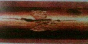
Mechanism of fatigue failure has been mostly found to be accompanied by certain features like residual stress, deformation of surface (sometimes resulting in even deformations of microstructure) & operating conditions like temperature etc. Several cases of failure investigations have concluded intense deformation of the material just below the affected or worn surface. Again, measured strain levels have indicated that the level from the material depth increases with nearer approach towards the affected region & reaches its apex at the place of action (damage). An in depth study reveals further detailed information with the help of advanced electron microscopy. The induced strain breaks down the grain structure at the surface to dislocation cells. Depending upon the stacking fault energy materials differ in their tendency to form dislocation cells. Materials with higher stacking fault energy form dislocation cells readily. Although the higher energy cell boundaries are likely to undergo void formation, but a crack may also originate at a weak point below the surface, thereby subsequent propagation to the surface causing material failure.
IJSER © 2012 http://www.ijser.org
International Journal of Scientific & Engineering Research Volume 3, Issue 7, July 2012 2
ISSN 2229-5518
Thus, certain vital factors having definite influences upon the fatigue life of a material can be stated as follows:
Residual stresses can be considered to be the induced stresses, which are entrapped within a material & thereby affecting its mechanical properties like toughness, strength etc. However, these types of stresses have major contributions towards a failure which can be revealed by metallurgical studies but since they don’t remain confined to material surfaces and can persist at any depth within a material, so their detection appears to be a major technical challenge before final failure.
origin of the cracks but they always produce thick walled fractures on equipment material. Mostly materials subjected to high residual stresses (resulting from manufacturing processes like welding), high stress levels during operation or service and locations exposed to water/ vapour contact (which can acts as corroding agent), can experience this process of failure. However, nature of tensile stresses for failure cases may be different. In some cases, stress approaches the yield point while in others, the stresses remain well below that point. But, a threshold value of stress exists in all cases which confirm the case of Stress Corrosion cracking. Stresses occurring from thermal contributions, service loads & pressure can be considered as applied stress and such types also account for a good number of failure cases.
Apart from the mention worthy features of fatigue failure, there are more features of this particular family of failures. Some of them are just the combinations of two or more individual features which may affect the intensity & depth of crack, but yet mention can be made of another type called Corrosion Fatigue. As clear from its name, the process takes place from the interaction between corrosion and fatigue. It should be remembered that all
International Journal of Scientific & Engineering Research Volume 3, Issue 7, July 2012 3
ISSN 2229-5518
the features of fatigue failure that has been described till now is not related to any particular case and
applies to any industrial domain, provided its criteria are fulfilled. The objectives of our experiment with stress- strain measurements are related to certain basic concepts regarding the occurrences of stress-strain at industries and their consequences.
Digital Image Correlation has proved to be a dependable instrument for deformation measurements of objects and also covers a wide domain in the study of mechanics. The method is mainly concerned with the process of reconstructing displacements of sub-pixel accuracy and tangential surface strain in the sub milli strain level. Although the basic features remain the same, but the system can be well operated in both 3D as well as 2D modes. With certain additional induced software capabilities, both the modes can be well handled from a single system. Hence, a typical experimental set up will be requiring- Work Station Computer (with the image correlation software) for processing of images, a high intensity light source (for high resolution imaging & proper identification of spots), CCD Cameras (two), lenses with required focal lengths (as per the object distance & configurations), an artificial mechanical deformer or clamper (for introducing stress-strain in an object only in case of an experiment) and the object or the
sample for testing. However, it must be kept in mind that digital image correlation is a measurement system which
has well established utilisation both in the areas of experimental mechanics (object deformation) as well as for research activities related to some residual stress predictions wherever possible. Particularly, the initiatives of estimation of residual stress can be very vital in cases of equipment failure where residual stress performs key role. But, accurate determination of the scope of such work at industrial domain remains a challenge. Again, every system has its own limitations in terms of accuracy, popularly considered as system errors and they have more distinct features in case of advanced sophisticated systems. Among them, mention can be made of statistical and systematical errors resulting due to system calibration, intrinsic noise of the obtained images, pixel effects due to limited camera resolution and lastly the uncertainties of the correlation algorithm. Among these, statistical errors can be prevented to some extent by proper filtering method but there is no such technical remedial measure for systematical errors. Since, it is already known that an accurate monitoring of equipment always help in the improvement of results & hence, likewise the parameters like contour, displacements and strain rates are affected positively. The main technical objective of a Digital Image Correlation system is to determine the strain rate at different points of an object or test sample. It works efficiently on textured objects & therefore sample preparation includes painting of the test samples with spray paints to produce the points or textures. Finally it should be remembered as the chief technical feature of the instrument that the process of image comparison has a vital role in concluding the results, since the instrument works upon strain or displacement field. It means correct calibration procedure and even comparison of images of a particular test sample at points of maximum and minimum stresses, will help to reach a decisive conclusion. However, the later experimental sections will provide more specific justifications behind this technical fact.
International Journal of Scientific & Engineering Research Volume 3, Issue 7, July 2012 4
ISSN 2229-5518

Before proceeding towards the guiding scientific phenomenon and mathematical expressions, a simplified description of the operating features is required to understand the basic objectives of operation. The image correlation provides the displacement field while the required strain field is achieved by numerical deviations of the displacement field. The correlation algorithm uses grey value interpolation to obtain sub pixel accuracy. In this respect it should be mentioned here that optimisation algorithms are utilised to calculate the displacement transformation parameters. Images remain discrete and interpolation helps in the reconstruction of continuous information. Digital Image Correlation matches the gray level of image patches considering their similarity (as shown in the fig.). Having its origin in 1983 (M.A.Sutton et al), the technique of Digital Image Correlation works
upon certain fundamental mathematical relations and transformations. The Levenberg-Maquardt algorithm
finds applications in those mathematical expressions for transformation purposes. This type of algorithm can be stated as an iterative tool that locates the minimum of a multivariate function, expressed as the sum of squares of non linear real valued functions. It has emerged as the widely accepted standard technique for non linear least squares problems in variety of disciplines. The algorithm behaves like the steepest descent method when the current solution is far from the correct one while the same approaches like Gauss-Newton method when the current solution is near to the correct solution & hence the algorithm can be considered as a combination of the two methods.
International Journal of Scientific & Engineering Research Volume 3, Issue 7, July 2012 5
ISSN 2229-5518
However, the method of DIC follow some universally accepted & established outlines:
i) A mathematical correlation criterion between two discrete functions.
ii) Required interpolation method for the grey level
of the images to reach sub pixel accuracy. iii) The mathematical solution for the estimation of
the strain term for a pattern.
iv) The mathematical definition of the displacement field on a pattern to be included along with the terms of strain and rigid body.
The image of a body could be represented by a discrete function and the correlation estimation is carried out for a group of pixels, also known as patterns. The initial image of the body or sample is a discrete function let C(x,y) before distortion, which will be transformed into another discrete function let C*(x*,y*) after distortion.
Thus the relation can be given a mathematical expression, C*(x*,y*) – C(x + u (x,y), y + v(x,y) = 0
Again, the commonly used correlation co efficients are the crossed and the least square co efficients,
I1 = ʃ S (C (x,y) – C*(x*,y*))2 dx.dy
&
I2= 1- ʃ S C(x,y) – C*(x*,y*).dx.dy /√ʃ S C(x,y)2.dx.dy .
ʃ S C*(x*,y*)2.dx.dy
(Where I1 & I2 = correlation co efficients; S= surface of the pattern in the initial image)
All these expressions remain the basic tools of calculation, while some more steps are performed for arriving at the
final results. Primarily, the pixels remain the chief parameters of such operations.
From the initial and final images, one can define different zones of study and analysis. Now, a vital operation is implemented in terms of calculation in a workstation with the help of algorithm (programmed in several languages) and a detailed result is obtained in several domains like the displacement field, the strain field, vector representation of the displacement field & the deformation mesh. In case of 3D’s, the digitized images are compared to match subsets or the facets using the correlation algorithm and with the knowledge of the imaging parameters of each CCD camera along with their orientations with respect to each other, the position of each object point in three dimensions is calculated. The observed gray value patterns for each camera are tracked by the algorithm, which also transforms corresponding facet positions in the two cameras into 3D co ordinates for each step. As a result, a track of each surface facet in 3D is created and from the point wise deformation, displacements of individual surface points with subsequent surface strains can be estimated.
In DIC Technique, a 3D experiment is concerned with the technical involvement of both the CCD cameras and since stress-strain measurement in equipment deformation has been a major industrial interest, hence the technical description of 3D imaging is highlighted mainly. The objective of the calibration remains to determine the imaging parameters along with the external positions and orientations of the cameras with respect to global co ordinate system. Proper calibration can be considered as the limitations of the system operation and any error in this process is likely to be affecting the system’s performance in terms of results obtained.
International Journal of Scientific & Engineering Research Volume 3, Issue 7, July 2012 6
ISSN 2229-5518
The calibration algorithm utilises a model according to
which the projection of the object point on the CCD is
Say,
S= (x, y, z) be the real position of a reconstructed
defined by the intersection of the line from the object point through the principle point and the CCD. The position of the optical axis on the CCD is provided by the projection on the image plane. Any deviation from the straightness of the projection can be related to the radial as well as tangential distortion. The resulting experimental data uncertainties may have their origins from different sources. The causes can be categorised as i) correlation errors (affecting the accuracy of image correlation) & ii) reconstruction errors (affecting the reconstruction of the co ordinates of correlated facets). Correlation errors represent uncertainties for the correlation of corresponding facet positions in different image frames and are of two types viz. a) Statistical & b) Systematical errors.
Reconstruction errors can be taken as the contributions of
the uncertainties in calibration parameters, which appear
in a systematical manner as a function of the facet positions in the camera frames, thereby causing local distortions of the constructed 3D space. Now let us state a mathematical expression, to represent the influence of distortions on 3D experimental results:
point.
Hence, the measure co ordinate SI differs from S by a
deviation vector ΔS.
In the vicinity of a point S0 = (x0, y0, z0), the error vector![]()
can be expressed as,![]()
![]()
![]()
![]()
![]()
ΔS (S0+ r ) = ΔS( S0 ) + k . r![]()
k = (kx, ky, kz) = kxx kxy kxz = Distortion matrix. kyx kyy kyz
kzx kzy kzz![]()
![]()
As a result, the displacement d of a point moving from the co ordinate S1 = (x1, y1, z1) to S2 = (x2, y2, z2) can be calculated as,![]()
VI = (1 + k0). V
Here k = function of the position in space.
International Journal of Scientific & Engineering Research Volume 3, Issue 7, July 2012 7
ISSN 2229-5518
From the previous discussions, it becomes clear that both in industrial sectors (cases of equipment deformation)
and in experimental study of mechanics (residual stress), the DIC has successfully proved its contributions. Hence, in this experiment the objective remains to observe the determination of the effects in terms of strain due to artificially induced stress in 2D mode. In specific industrial applications like bearing industries, power sectors, aviation, locomotive & automobile design, DIC techniques may proceed in various ways (in 3D or 2D mode) but the basic principle & the objective remains the same.
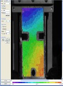
In this experiment a thin rectangular metal sheet has been taken for strain estimation with Digital Image Correlation system in 2D mode. The material of the test sample is alloy steel and a hole is drilled to induce some artificial stress into it. The test piece is to be sprayed with paints to produce a textured surface. The lenses along with the whole DIC system are set as per the distance & image specifications and the light source and its intensity is to be adjusted as per the view of the workstation, since both excessive as well as deficient light will degrade the image quality. This may also result in erroneous stress- strain estimation at the desired points. The test piece is then clamped in a mechanical clamper. Proper calibration is then conducted with a series of comparative images. Care is to be taken so that the whole arrangement remains stress free or minimum stress is applied on the sample, as the experiment requires a set of images at various levels of stress (the initial essentially at the lowest level) for reaching the result.
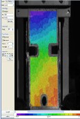
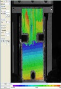
The various points at the respective strain levels are indicated by colours, stated at the bottom. The software calculates the strain field from the displacement field and provides a final result with the vectors. In image (a), the sample is at the least or zero stress as also indicated by the colours. In the images (b) & (c), the stress goes on increasing and these are well indicated by the change of shades. Such type of observations can really play a vital role to estimate stresses before the final equipment failure. We are already familiar with a comparable
advanced approach of stress-strain calculation but in design field and that is universally known as Finite
Element Analysis method with Analysis Software. Today, FEM has turned out to be one of the most dependable tools of making major decisions like Bridge Construction, Aviation, Automobile Design, etc. Similarly, with its advanced capabilities Digital Image Correlation is also becoming a tool in Condition Monitoring operations in Industrial R&D applications besides its significant role in the field of mechanics at the well known laboratories.
The author expresses deep honour & gratitude to all the scientific as well as the industrial communities who have paved the way for the advances of Digital Image Correlation Systems. The author also conveys regrets that the limits of this paper may fall too short to mention all of their esteemed names & identity. This paper is dedicated to the devoted activities of scientists, academicians, technologists, research and industrial personalities for their significant contributions to the study of stress-strain experimental analysis with their industrial applications.
i) Dr.U.S.Ghosh, Central Mechanical Engineering Research Institute, a Constituent Establishment of Council of Scientific & Industrial Research, India.
ii) Indian Society for Non Destructive
Testing, India.
iii) Dr.M.Sarangi, Indian Institute of
Technology, Kharagpur, India.
iv) To all the equipment manufacturers, for
carrying out advanced research in the field of Digital Image Correlation.
International Journal of Scientific & Engineering Research Volume 3, Issue 7, July 2012 8
ISSN 2229-5518
1) An evaluation of short penning, residual stress and
stress relaxation on fatigue life of A1S1 4030 steel, M.A.S Torres, H.J.C. Voorwald, International Journal of Fatigue,24 (2002) 877-886.
2) Residual stress measurements that correlate fatigue
and facture behaviour, Michael.R.Hill, Residual
Stress Summit, 26th Sep. 2010.
3) Various Experimental Applications of Digital
Correlation Method, S.Moguil Touchal, F.Morestin, M.brunet, Laboratoire de Mécanique des Solides, INSA de Lyon, Unknown.
4) Bruck. H. A., McNeill. S. R., Sutton, M. A. Peters, W. H. Digital Image correlation using Newton- Raphson Method of Partial Differential correction, Experimental Mechanics, 1989, 261-26.
5) Chu, T. C., Ranson. W. F., Sutton. M. A.,
Peters.W. H. Application of Correlation Techniques to Experimental Mechanics, Experimental Mechanics, 1985, 232-244.
6) Sutton.M. A., Mingqi cheng, Peters.W. H., Chao. Y.
S., McNeill.S. R. Application of an optimized digital
correlation method to planar deformation analysis, Image and Vision Computing, vol 4 n°3, 1986, 143-
150.
7) Sutton. M. A., Wolters.W. J., Peters. W. H.,
Ranson.W. F., McNeill.S. R. Determination of displacements using an improved digital correlation method, Image and Vision Computing, vol 1 n°3,
1983, 133-139.
Saswata Bhowmick is a Mechanical Engineer with professional specialisation in Machine Operations. He has obtained a BTech Degree in mechanical engineering from West Bengal University of Technology but has started his career by joining as Junior Supervisor in a Chain Industry under private concern even before pursuing engineering degree. During, his engineering career, he received several acknowledgement certificates and awards for remaining associated with academic as well as research projects in various Reputed Industrial (mostly at the Thermal Power Stations) and R&D Organisations and is also attached with prestigious professional organisations like American Society of Mechanical Engineers, Indian Society for Non Destructive Testing & others as member/delegate. His areas of interest & fields of
research include NDE Engineering, Plant Engineering & Maintenance, Power Engineering & Tribology.
The author has received award of Research Fellowships &
conducted doctoral level research under Mechanical
Engineering Dept. at Indian Institute of Technology, kgp. He joined Research & Development Centre under Indian Institute of Technology, Kharagpur (established under a Power Plant based Project) as a Technical Assistant & is presently associated as a Sr. Scientist and Research Officer, NDE and Tribology Laboratories in the same organisation. He also serves as a Visiting Scientist to some professional organisations for addressing various industrial problems and briefings.