International Journal of Scientific & Engineering Research, Volume Ŝǰȱ ȱŗǰȱ ¢ȬŘŖŗśȱ 50
ISSN 2229-5518
Different Systems to Store Nucleotides
Information
Carlos Llopis, Silvia Llopis, Jose Daniel Llopis
Abstract— in the last years a lot laboratories and scientific centers around the world generate a huge amount of genetic information, o ne reason is because the price of massive sequencing is down, being very cheaper, if you compare previous years, to sequence par t or whole genome of any living thing. By this reason, they generate huge amount of genetic information, which part of this genetic information are discarded or transformed. In this article we can describe several systems and methods to store whole nucleotide information, also these methods can reduce final file size, being later these files very easy to manipulate.
Index Terms—Nucleotide, File, System, Storage, DNA.
—————————— ——————————
1 INTRODUCTION
t’s normal in recent years can see a lot of news about ad- vantages in biotechnology, in particular with genetic field, for example, in 1996 several Scientifics cloned a sheep in United Kingdom [1] [2](called dolly), being the principles of cloning and first steps with stem cells studies, also, recently in the same and next century, others Scientifics have sequenced all human’s genome [3] [4], by these discoveries and other, today, we know more about human being and its characteris- tics, and answer big questions about life and other living things, not all are answer, but step by step. Mains goals in last years have been discovered diseases or mutations in specific parts of human’s genome (in special with a particular genes or
chromosomes) [5].
Thanks to these great discoveries and one growing in build more cheapest and strong DNA sequencer machines, more institutions or organizations produce huge amount of genetic information in theirs analysis process. At the moment, almost big part of this genetic information are trashed, because these centres have not specific system to store this huge amount of genetic data, thus, if these centres can store that data, being very difficult manipulate genetic data for them, because, nor- mally to access files with a huge size for any operating system or similar is a hard task.
First steps in science of genetics, it's to mid-19th century, with the applied and theoretical works of Gregor Johann Mendel [6], other theories of inheritance preceded Mendel. The con- cept blending inheritance is main theory in that time. Where main idea is that individuals inherit a smooth blend of traits from their parents. In consequence these theories and subse- quent theories with same way of Mendel’s theories, big part of Scientifics that time believed main topic on inherence is rela- tionship with the proteins, it was not until recent centuries and modern research such as Watson-Crick’s discovery, deox- yribonucleic acid (DNA), that DNA is cornerstone at inher- ences process and origin of life.
Watson-Crick’s discovery [7], the double-helix, it is model had two strands of DNA with each nucleotide matching a com- plementary nucleotide, on the other strand, to form what looks like rungs on a twisted ladder. This structure showed that genetic information exists in the sequence of nucleotides on each strand of DNA. The structure also suggested a simple method for duplication: if the strands are separated, new partner strands can be reconstructed for each based on the sequence of the old strand. As we said before, nucleotides in the same strand have not restriction to join one with another nucleotide, but with nucleotides of different strands exist complementary rules, i.e. for all Adenine nucleotide can con- nect by Hydrogen Bridge with any Thymine nucleotide and vice versa, in the same way, any Cytosine nucleotide can con- nect by Hydrogen Bridge any Guanine nucleotide and vice versa, in some occasions and rarely, in nature or by artificial way exist mutations or another anomaly with connections between others nucleotides such as; one Adenine with one Cytosine, and others abnormal junctions. These abnormal forms have weak bridges to connect both nucleotides, by this reason, they are more unstable and break the bridge with easi- ly, because, these organic structures tends to normal form and to create normal connections.
In another case, the different nucleotides in a DNA strand are represented with characters or letters (A, T, C and G), that characters are first character of nucleotide bases, where A de- picts Adenine, T depicts Thymine, C depicts Cytosine and G depicts Guanine. Also, to store these nucleotides in computer files, these characters could be represented with eight bits (byte), using ASCII codification or ASCII extends version, which is possible to write special characters, i.e. character with special format or characters are not in English alphabet.
Note, when the file has smaller, there is no problem to access it, because all data can be manipulated in a virtual memory of the system, but, when file is bigger, it’s very difficult to access
it, because the system need to divide it in several pieces (size
IJSER © 2015 http://www.ijser.org
51
International Journal of Scientific & Engineering Research, Volume Ŝǰȱ ȱŗǰȱ ¢ȬŘŖŗśȱ
ISSN 2229-5518
of virtual memory of the system) to manipulate it. By this rea- son, there are a lot swaps operations in the virtual memory and the system is very slow and inefficient.
At the moment, different organizations and institutions need huge data centres and complex systems to store and manipu- late that genetic information. By this reason, it is necessary to use script languages, other software utilities (using abbrevia- tions of DNA parts) or special hardware to analyse easily any DNA strands inside of some huge files.
2 NUCLEOTIDE FILES FORMAT
There are a lot formats to store genetic data, where ones are very simple and others are very complex, which contain addi- tional information about DNA sequence. For example, one simple format is a plain Sequence without additional infor- mation and special characters, only A, T, C, G, break line and space characters. This file format can store several sequences inside it, where space or break line can separate one sequence of other sequence.
EMBL format [8] is other system to codify DNA sequences. In this format can write general information about sequence(s) as genetic data of sequence(s). Inside of file, one sequence starts with an identifier line (label “ID”), followed by further annota- tion lines. A line with label “SQ” marks the start of the se- quence and two slashes (“//”) marked the end of the se- quence.
FASTA [9] is other format; each sequence in FASTA format begins with a single-line description, followed by lines of se- quence data. The description line must begin with a greater- than (">") symbol in the first column.
CGC format contains exactly one sequence, begins with anno- tation lines and the start of the sequence is marked by a line ending with two dot characters. This line also contains the sequence identifier, the sequence length and a checksum. This format should only be used if the file was created with the GCG package.
GENBANK format can contain several sequences. One sequence in GENBANK format starts with a line containing the word LO- CUS and a number of annotation lines. A line containing “ORIGIN” marks the start of the sequence and the end of the sequence is marked by two slashes ("//").
IG format can contain several sequences, each consisting of a number of comment lines that must begin with a semicolon (";"), a line with the sequence name (it may not contain spaces) and the sequence itself terminated with the termination character '1' for linear or '2' for circular sequences.
Some GENOMATIX tools, e.g. Gene2Promoter or GPD allow the extraction of sequences. GENOMATIX uses the following
syntax to annotate sequence information: each information item is denoted by a keyword, followed by a "=" and the value. These information items are separated by a pipe symbol "|".

In general, all file formats showed above are very similar ones or others, because all contain DNA sequence at the bottom and special characters as limiters. Thus, there are rules to rep- resent DNA sequences of the International Union of Pure and Applied Chemistry (IUPAC); the following letters can be used.
A = Adenine
C = Cytosine
G = Guanine
T (or U)= Thymine (or Uracil)
R = A or G
Y = C or T
S = G or C
W = A or T
K = G or T
M = A or C
B = C or G or T
D = A or G or T
H = A or C or T
V = A or C or G
N = any base
. Or - = gap
As we said before, these files are composed with genetic in- formation and/or general data, where A, T, C and G charac- ters represent nucleotides and R, Y, S, W, K, N, M, B, D, H and V represent anomalies or special situations in strand or indi- vidually in any nucleotide: as mutations, holes, etc.
Normally, any DNA sequence is stored in file by means of ASCII codification, using follow letters: A, T, C and G (in up- percase or lowercase format), but sometimes is possible to find other variations (accents, bold, cursive or orthographic sym- bol) of these characters to indicate quality, degree of purity, anomalies or other important skills about nucleotide or in general whole DNA strand.
Note, normally in these files only are stored primary DNA strand, because with this way, we can save a lot space. But in last years, several Scientifics have discovered mutations in complementary strand, due some specific diseases or natural way, which can change internal structure of DNA strand. In consequences, actually it is very important to store both strands, using methods or systems to store huge amounts of genetic data in less space. Note, these systems must be very easy to access and can obtain quickly original source, without loss of information during of processes (read or write).
3 STORAGE SYSTEM
In the present article, we have been described three versions to store DNA data or nucleotide information, depending of host
IJSER © 2015 http://www.ijser.org
52
International Journal of Scientific & Engineering Research, Volume Ŝǰȱ ȱŗǰȱ ¢ȬŘŖŗśȱ
ISSN 2229-5518
system or final user (you can see Fig. 1, Fig. 2 and Fig. 3).
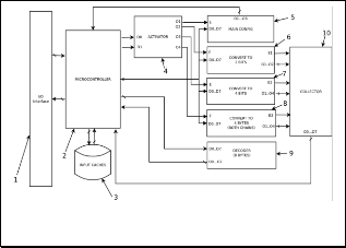
Fig. 1. Codify / compress any genetic information, and final
result is file.
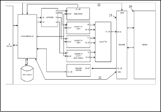
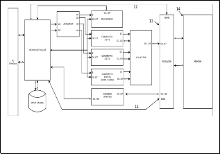
Fig. 2. Codify / compress any genetic information and system stores in normal memory system.
Fig. 3. Codify / compress any genetic information and system stores inchrosil memory system.
Main objective of these systems can connect with another sys- tem/devices, by this reason; it needs an input/output inter- face (I/O) (Fig 1.1) to connect with external system, such as:
USB, PCI or another kind of connector at the market. High- light, this interface described above is the same in rest of sys- tems (Fig. 2 and Fig. 3).
On the other hand, I/O interface (Fig. 1.1) is a communication bridge between internal system and external world, where the inputs are signals or data received by the system, thus, out- puts are signals or data send from it. By this reason, I/O inter- face (Fig. 1.1) receives all signals or data (information of DNA files or nucleotides files) in different file formats (which are described above). Also, I/O interface (Fig. 1.1) can receive ad- ditional information to configure the system (codification in two or four bits at the outputs/inputs, or the system uses one or two DNA strands in the codification).
We can consider several kinds of codifications of nucleotides, for example in the case of 2 bits codification, next list shows internal codification (which has used in [10] [11]):
A (Adenine) = 00
C (Cytosine) = 10
G (Guanine) = 01
T (Thymine) = 11
In the case of 4 bits (where X depicts a mutation or hetero- plasmy, Z depicts one position not active and N1/N2 depicts both positions activate, where N1 is nucleotide first strand and N2 is nucleotide second strand):
A/X = 0000 = 0 G/X = 0100 = 4 C/X = 1000 = 8 T/X = 1100 = 12
Z/A = 0001 = 1 Z/G = 0101 = 5 Z/C = 1001 = 9 Z/T = 1101 = 13
A/Z = 0010 = 2 G/Z = 0110 = 6 C/Z = 1010 = 10 T/Z = 1110 = 14
A/T = 0011 = 3 G/C = 0111 = 7 C/G = 1011 = 11 T/A = 1111 = 15
Normally inputs DNA data are codified by ASCII characters such as illustrate next lines (considering, upper and lower case):
A = 65 = 01000001 a = 97 = 01100001
T = 84 = 01010100 t = 116 = 01110100
C = 67 = 01000011 c = 99 = 01100011
G = 71 = 01000111 g = 103 = 01100111
Z = 90 = 01011010 z = 122 = 01111010
X = 88 = 01011000 x = 120 = 01111000
In this communication is necessary a protocol to generate all messages or packages. By this reason, first byte is a code, be- ing first four bits action to do (read or write) and last four bits are particular operation / codification to do, next lines show different combinations of these last four bits:
“0000” or 0 indicates the action to configure final output codification.
IJSER © 2015 http://www.ijser.org
53
International Journal of Scientific & Engineering Research, Volume Ŝǰȱ ȱŗǰȱ ¢ȬŘŖŗśȱ
ISSN 2229-5518
“0001” or 1 indicates any nucleotide of eight bits can
convert to one nucleotide of two bits.
“0010” or 2 indicate any nucleotide of eight bits can convert to representation of four bits, where codification is as follow N1/N2 (both active).
“0011” or 3 indicates that the combination both
nucleotides (primary and secondary strand), almost
sixteen bits, can convert to representation of four bits.
Next bytes are name, internal ID or physical address in the memory. This information is very important to localize any DNA file in the system. Also, this information is unique in the system, because it is best way to solve ambiguities to look for different DNA files. Note these bytes are included at input mes- sages as in outputs messages. Finally, rest of bytes are genetic information stored in DNA files with specific format.
All these data received is sent to microcontroller (Fig. 1.2, the same in rest of the systems), which its main function is to re- ceive, classify and send data to different parts of system. As we said before, first bytes are operation, codification and address. Once detecting and interpret these bytes, the systems have one module is called “activator” (Fig. 1.4, the same in the rest of the systems) to activate specific module to do some particular pro- cedures or functions (decoding, configuring or other action).
Also, the microcontroller (Fig. 1.2) can separate all genetic in- formation to the general data, further the microcontroller (Fig.
1.2) convert all genetic data from any format to plain sequences (only chains with nucleotides, spaces and break lines), with this way is easy later to codify genetic data. Finally, microcontroller (Fig. 1.2) can manipulate and store any data configuration, which is necessary in decoding and coding processes.
Microcontroller (Fig. 1.2) has an internal memory or cache (Fig.
1.3), where it stores all temporal and permanent data about
DNA files, i.e. any configuration data, general information
about DNA file, etc. By this reason, microcontroller (Fig 1.2) access frequently to cache (Fig. 1.3) by means of one bidirection- al bus.
Each module of system (Fig 1.5, 1.6, 1.7 and 1.8, similar in the rest of systems) has an input (enable input) connect to each out- put of the activator (Fig 1.4), when microcontroller (Fig 1.2) re- ceive initial byte, it uses only last two bits and puts these signals at the inputs of activator (Fig 1.4), later, activator (Fig 1.4) inter- prets these inputs and activates one of its outputs.
The systems have four modules (Fig 1.5, 1.6, 1.7 and 1.8); first module is called “configurator” (Fig 1.5), which interprets and manipulate data configuration. Once interpreted all data, (Fig
1.5) send to (Fig 1.2), and later, (Fig 1.2) store all these data in caches (Fig 1.3), because these data is useful in all coding and decoding procedures.
Thus, second module (Fig 1.6) codifies eight bits of genetic data in two bits data, without using the complementary DNA strand, only primary strand. Next module (Fig 1.7) codifies same eight bits of genetic data to four bits, using codification described above, in this case, too without secondary strand.
Finally, forth module (Fig 1.8) codifies both DNA strands (six- teen bits per pair of nucleotides) in four bits genetic data, by this reason; it is possible to create an exact representation of real DNA strand. The differences between module (Fig 1.7) and (Fig
1.8) are mainly with module (Fig 1.8) can create DNA strands with holes or mutations and module (Fig 1.7) not, also in mod- ule (Fig 1.8) use a lot information to codify genetic data.
All modules are connected with the microcontroller (Fig 1.2) by data bus, by this reason, (Fig 1.2) can send data any time. Dur- ing coding process in (Fig. 1), there is a module is called “collec- tor” (Fig. 1.10, exclusive only for this system), which collects all final results of modules (Fig 1.6, 1.7 and 1.8), and later, it creates eight bits words with this data collected. Once bytes are created, in this version of system send all these bytes to microcontroller (Fig 1.2) by means of data bus. Later (Fig 1.2) take general in- formation about that specific DNA sequence(s), which are stored in cache (Fig 1.3), and all bytes received and (Fig 1.2) cre- ates a file or package about this information. With this new file or package is send to I/O interface (1), and finally (Fig 1.1) send outside of the system as text file.
Note, system of (Fig. 1) doesn’t store any data inside; only it creates a compact file, which could be compressed for other system or hardware (obtaining with this method, smaller files than original file). Highlight, with this method, the system don´t compress any data or information, only it compacts genetic data without loss of information and it obtain a small size.
Using method described above, we can obtain savings around
75 % of total space (file size) with two bits of codification. Thus,
using four bits of codification without complementary strand, it
is possible to obtain savings around 50 % of total space, finally,
using four bits of codification and both strands, we can obtain
75 % of savings and a real structure of DNA strand.
In the other hand, with the system of (Fig. 2), it is possible to store genetic data inside of system. The version two (Fig. 2) has same component and structure of version one (Fig. 1), unique difference between both versions is the version two (Fig. 2) has additional components, where all bytes codified don´t return to the microcontroller (Fig 1.2), by this reason, there is a new mod- ule (Fig 2.13, unique in this system – Fig. 2) to package all bytes codified and to get one address inside of host memory (Fig 2.14, unique in this system), this new module is called “packager” (Fig 2.13, unique in this system).
Note, any name of final file is sent from the microcontroller (Fig
1.2) to packager (Fig 2.13), and packager (Fig 2.13) checks file name about ambiguities or duplicities, because in same memory
IJSER © 2015 http://www.ijser.org
54
International Journal of Scientific & Engineering Research, Volume Ŝǰȱ ȱŗǰȱ ¢ȬŘŖŗśȱ
ISSN 2229-5518
cannot there are two files with the same name. Finally, in any write operation with version two, the system stores the DNA file into (Fig 2.14) in specific address with one unique name. Note, host memory could be any commercial memory system (solid-state memories, hard disk or other kind of memories).
On the other hand, with read operation, microcontroller (Fig
1.2) received file name, later, microcontroller (Fig 1.2) send all
data to packager (Fig 2.13), which look for file by its name in
host memory (Fig 2.14). Once to find it, DNA file is separated in
two parts; one is generic data and other the general information
(this last part could be optional, depend of format).
With general data is sending directly to microcontroller (Fig
1.2), thus, genetic data is sending to other module, which is
called “decoder” (Fig 1.9). This module converts any compact
data (eight bits format) to original format. Note, when DNA file
is compacted and written into memory (Fig 2.14), in its general
information is included the codification used, by this reason, in decoding process it is very useful for decoder (Fig 1.9), because it knows which codification has been used in writing process
and it can decode data compacted.
Finally, the microcontroller (Fig 1.2) join both information (gen- eral and genetic data), and later microcontroller (Fig 1.2) sends to I/O interface (Fig 1.1). Note final result is a DNA file with same format that before enter in system. Also, both processes (decoding and coding), there is not loss of information, because, system don´t compress data, but system compact data, i.e. it changes codification of genetic data, by this reason, final results are very easy to access and manipulate.
In same way, version one (Fig. 1) can decode/code any genetic data, but the unique deference between versions (Fig. 1 and Fig.
2) is in version one (Fig. 1) cannot store nothing inside of sys- tem, it returns everything to microcontroller (Fig 1.2). Note in version one (Fig. 1) has decoder (Fig 1.9) module for any decod- ing processes.
Last version, version three (Fig. 3), can store inside the system any DNA sequence file as version two (Fig. 2), but the differ- ence between both versions is in version two (Fig. 2) has used normal system memory (Fig 2.14), thus, version three (Fig. 3) has used INCHROSIL memory (Fig 3.16) [11] [10]. Also, version three (Fig. 3) changes the module is called packager (Fig 2.13) for another module (Fig 3.15, unique in this system), most ap- propriate to access and manipulate this kind of memory (INCHROSIL).
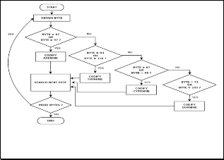
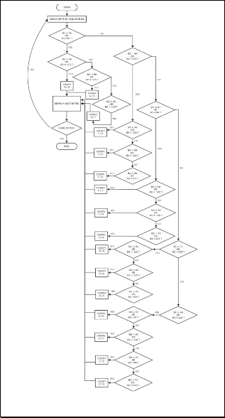
All coding processes may be illustrated in Fig. 4 and Fig. 5. In particular, Fig. 4 shows flowchart to codify an ASCII word in two bits or four bits codification, but without se- cond/complementary strand. On the other hand, Fig. 5 shows flowchart to codify genetic data of both DNA strands (primary and complementary) in a four bits codification.
Finally, decoding processes may be illustrated in Fig. 6 and Fig.
7, in particular Fig. 6 shows a flowchart to convert four bits code
to two eight bits words, which represent both nucleotides of
DNA strand.
Thus, Fig. 7 shows a decoding process of two bits codification to eight bits words, i.e. in this process the initial byte is divided in four groups of two bits, which could be represented as a nucleo- tide, later this nucleotide is converted to ASCII code word. In general, the final results of decoding processes are ASCII words.
These systems can store RNA data, because it can code and de- code URACIL nucleotides (U or u), where their ASCII codifica- tion such as:
• U = 85 = 01010101
• u = 117 = 01110101
By this reason, these systems contain this variation, because in module where Thymine is detected and manipulated can be manipulate Uracil nucleotides, which are very specific of RNA strands.
In general, the systems can convert any DNA sequence or any RNA sequence in a compact format, by this reason, final user can store huge amount of genetic data in less space. Also, the system is very easy to connect to any host (Hardware or soft- ware), due any system can work with ASCII code and binary system.
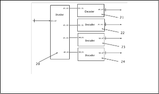
Fig. 4. Codification any nucleotide from ASCII to two bits.
Fig. 7. Decoding process of two bits codification to eight bits words.
IJSER © 2015 http://www.ijser.org
55
International Journal of Scientific & Engineering Research, Volume Ŝǰȱ ȱŗǰȱ ¢ȬŘŖŗśȱ
ISSN 2229-5518
4 CONCLUSION
With these system can store any nucleotide of DNA and RNA sequence in less space. In the future our research would use compression method with this system to obtain reduce nucleo- tide files.
REFERENCES
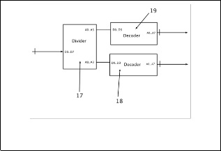
Fig. 5. Codification any pair nucleotide from ASCII to four bits.
Fig. 6. Flowchart to convert four bits code to two eight bits words.
IJSER © 2015 http://www.ijser.org