—————————— ——————————
International Journal of Scientific & Engineering Research, Volume 2, Issue 11, November-2011 1
ISSN 2229-5518
Different Pump Configurations for
Discrete Raman Amplifier
Arwa H. Beshr1, Moustafa H. Aly1# and A.K. AboulSeoud2
1 Faculty of Engineering and Technology, Arab Academy for Science, Technology and Maritime Transport Alexandria, Egypt, arwabeshr@gmail.com, drmosaly@gmail.com
2 Faculty of Engineering, University of Alexandria, Alexandria, Egypt, Aboul_Seoud_35@yahoo.com
# Member of OSA
Abstract— In a discrete Raman fiber amplifier, the gain depends strongly on the difference between the pump and signal wave lengths. One of the major attractive characteristics of Raman amplification is that, it can be used over a very wide wavelength range by multiplexing different wavelengths together. This paper describes the net gain of the discrete Raman amplifier (DRA) as a function of the fiber length at different pump configurations: forward pumping (co-pumping), backward pumping (counter-pumping) and bidirectional pumping. Also, input pump power as function of span length is presented. The signal and pump wavelengths are, respectively, 1550 nm and 1450 nm.
Index Terms—Discrete Raman Amplifier (DRA), Net Raman Amplifier Gain, Bidirectional Pumping, Counter pumping.
—————————— ——————————
he most important feature of fiber Raman amplifier is the stimulated Raman scattering, which is essentially
based on Raman effect discovered by C.V. Raman in
1928. He noticed the appearance of additional spectral
lines after a monochromatic light passed through transparent materials [1].
In the elastic scattering, both the incident light frequency and the scattered light frequency are the same as in Rayleigh scattering, while for the inelastic scattering a portion of the scattered light appears at a different frequency from the incident light frequency, as it is in the Raman scattering and the Brillouin scattering. It was due to the fluctuations of the material atoms or molecules from their normal state that influenced this scattering. The interaction between photons and the material molecules results in the energy transfer. This energy conversion occurs when a photon undergoes an inelastic collision with a molecule and energy is obtained from the material [2-4].
In the inelastic scattering process, the energy of the incident particle is lost or gained. When a photon is the incident particle, the inelastic scattering process is called Raman scattering.
Raman amplification exhibits the advantage of self phase
matching between the pump and signal together with a
broad gain bandwidth and high speed response in
comparison with the other nonlinear processes [5]. There
are two types of Raman amplifiers: discrete Raman
amplifier (DRA) and distributed Raman amplifier. The distributed type utilizes a transmission optical fiber as an
active medium [6]. If the amplifier is contained in a box at the transmitter or receiver end of the system, it will be called a discrete Raman amplifier.
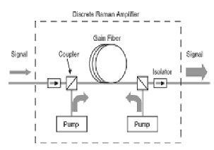
The basic configuration of discrete DRA is represented in Fig. 1. It generally comprises a gain fiber, a directional coupler for combining the pump and the signal wavelength, and isolators at the input and output ends.
Fig. 1. Schematic of an optical communication system employing
Raman amplification [7].
There are three pumping schemes:
1. Co-pumping, or Forward-pumping, where both
signal and pump are propagating in the same direction.
2. Counter-pumping or Backward-pumping, where
signal and pump are propagating in opposite directions.
3. The bidirectional pumping which includes both the co-pumping and counter-pumping, simultaneously.
The paper is organized as follows, the mathematical model of net gain of DRA for different pumping configurations are presented in Sec. 2. Section 3 displays and discusses the obtained results, based on the described model This is followed by the main conclusions in Sec. 4.
The evolution of the signal pump power, PS, and the pump power, PP, propagating along the optical fiber can be quantitatively described by the following propagation differential equations [7], [8]
IJSER © 2011 http://www.ijser.org
International Journal of Scientific & Engineering Research, Volume 2, Issue 11, November-2011 2
ISSN 2229-5518
![]()
(1)![]()
![]()
(2)
where gR(W−1.m−1) is the Raman gain coefficient of the fiber, normalized with respect to the effective area of the fiber, Aeff. s and p are the attenuation coefficients at the signal and pump wavelengths, respectively, ωs and ωp are the angular frequencies of the signal and pump. The signs of "+" or "–" correspond to forward and backward pumping.
Equations (1) and (2) show that the signal receives a gain proportional to the pump power with a proportionality constant given by the Raman gain efficiency. It has a loss due to the attenuation of optical fiber. At the same time, the pump power receives a loss due to the energy transfer to the signal and the attenuation of optical fiber.
Since PP >> PS, the first term in Eq. (1) is negligibly low compared with the second and therefore, its influence can
be neglected. So, Eq. (1) can be solved by integrating both sides.
This equation can be easily integrated to obtain [9]:
(3)
where P0 is the pump power at Z= 0, G(L) is the net signal gain, L is the amplifier length and Leff is an effective length defined as:
(4)
(5)
When using forward pumping, the pump power can be expressed as
calculate the pump power at point Z, one can use
(8)
If the values of pp are substituted in Eq. (2) and then integrating from 0.0 to L, the signal power in the forward and the backward pumping can be written, respectively, as![]()
(9)![]()
(10)
where Gf and Gb are the net gain of the forward and the backward pumping.
The net gain is one of the most significant parameters of the DRA. It describes the signal power increase at the end of the transmission span and presents the ratio between the amplifier accumulated gain and the signal loss. It can be simply described by [11]
(11)![]()
![]()
![]()
(12) It is useful to introduce the concept of the amplification
factor, GA, using the following definition [7]
(6)
![]()
(13)
In the backward pumping, the pump power is
where PP(0) is the value of the pump power at Z = 0.
(7)
Figure 2 shows the variation of GA with pump power P0. The amplification factor GA increases with P0, as predicted by Eq. (13), but starts to deviate for P0 > 1 W.
In the general case, when a bidirectional pumping [10] is used (0.0 < S < 1.0), the laser sources work at the same wavelength and at different pump power. Therefore, to
This is due to gain saturation occurring because of pump depletion. This is in a fair agreement with the data found
in Ref. [9].
IJSER © 2011 http://www.ijser.org
International Journal of Scientific & Engineering Research, Volume 2, Issue 11, November-2011 3
ISSN 2229-5518
Fig. 2. Variation of the amplifier factor, GA, with pump power P0.
We observe from Fig. 3 that, in forward pumping the pump power decreases exponentially versus span length, but in backward pumping the pump power increases exponentially versus span length.
Fig. 3. Variation pump power versus span length.
In Figure 4, the simulations are accomplished with the main pumping schemes forward, backward and bidirectional versus span length.
As predicted by Eq. (10), Eq. (11) and Eq. (12) when (S = 0) Ppf is equal to zero and Ppb is equal to 100%, which gives higher gain. This case is called backward pumping.
Also, we observe that, when (S = 0.5), Ppf is equal to 50% and Ppb is equal to 50%, which gives a lower gain .This case is called bidirectional pumping.
When (S = 0.75) Ppf is equal 75% and Ppb is equal 25%, resulting in higher gain than bidirectional pumping.
Fig. 4. Net gain versus span length in several pumping regimes.
Figure 5 presents the three cases of pumping within
S = 0, S = 0.5 and S = 0.65.
Fig. 5. Net gain versus span length for several pumping schemes.
In backward pumping, the higher gain occurs when (S =
0) and in bidirectional pumping, it occurs at (S = 0.5).
Based on the mathematical model, when (S = 0), Ppf
equals zero and Ppb equals 100%, which gives a higher gain in the backward pumping , as shown in Fig. 6. When
(S = 0.5, bidirectional pumping) Ppf equals 50% and Ppb equals 50%, which gives a lower gain than backward pumping.
IJSER © 2011 http://www.ijser.org
International Journal of Scientific & Engineering Research, Volume 2, Issue 11, November-2011 4
ISSN 2229-5518
Fig. 6. Net gain versus span length for different values of S for the different pumping schemes.
When (S = 0.10) Ppf equal 10% and Ppb equal 90% which give a lower gain than bidirectional pumping and backward pumping as indicated in Fig. 6.
Fig. 7. Net gain versus span length for different values of S for the different pumping schemes.
Figure 7 shows that, (S = 0) Ppf equals zero and Ppb equal 100% which give a higher gain so, this case called backward pumping and equals 102 dB.
When (S = 0.5) Ppf equal 50% and Ppb equal 50% which give a lower gain than backward pumping, this case called bidirectional pumping.
The case of forward pumping was reached when (S = 1) Ppf equal 100% and Ppb equal zero which give the lowest gain than bidirectional pumping and backward pumping Fig. 7.
Fig. 8. Net gain versus span length for different values of S for the different pumping schemes.
When (S = 0.90) Ppf equals 90% and Ppb equal 10% which give the lowest gain, when (S = 0.80) Ppf equal 80% and Ppb equal 20% which gives a higher gain than previous case, when (S = 0.70) Ppf equal 70% and Ppb 30% which give the highest gain of these cases Fig. 8.
In this study, we described the net gain of DRA as a function of fiber length at different pump configurations: forward pumping (co-pumping), backward pumping (counter-pumping) and bidirectional pumping.
We studied the important parameters representing the net gain of discrete Raman amplifiers as a function of different fiber length which gives the highest and lowest gain. The simulation has been done by using matlab 7.0 software simulations at the signal and pump wavelengths
1550 nm and 1450 nm, respectively.
Finally, we reach the maximum Raman gain which
equal 102 dB when (S = 0) counter pumping and minimum
Raman gain which equal 10-2 dB when (S = 1) Co-
pumping.
We reached a lower gain in case of forward pumping, a higher gain in backward pumping and a medium gain in
bidirectional pumping.
[1] C.V. Raman and K.S. Krishnan, ‖A new type of secondary radiation,‖
Nature, vol. 121, pp. 501-503, 1928.
[2] G.P. Agrawal, Nonlinear Fiber Optics, Academic Press, San Diego, 2001. [3] Milorad Cvijetic, Optical Transmission Systems Engineering, Artech
House, Inc. Boston, London, 2004.
[4] Rajiv Ramaswami, Kumar N.Sivarajan, Optical Networks, 2nd ed., Academic Press, 2002.
[5] John N. Senior, Optical Fiber Communications: Principles and Practice,
3rd ed., Printice Hall, New York, 2009.
[6] H. S. Seo, Y. G. Ghio and K. H. Kim, ―Design of transmission optical fiber
with a high Raman gain, large effective area, low nonlinearity, and low
IJSER © 2011 http://www.ijser.org
International Journal of Scientific & Engineering Research, Volume 2, Issue 11, November-2011 5
ISSN 2229-5518
double Raleigh back scattering,‖ IEEE Photonics Technology Letters, vol.
16, pp. 206-208, Jan. 2004.
[7] Ch. Headley and G. Agrawal, Raman Amplification in Fiber Optical
Communication Systems, Elsevier, 2005.
[8] M. Islam, ―Raman amplifiers for telecommunications‖, IEEE Journal of
Selected Topics in Quantum Electronics, vol. 8, no. 3, June 2002.
[9] G. P. Agrawal, Nonlinear Fiber Optics, Academic Press, San Diego, 1995. [10] S. Raghuawanshi, V. Gupta, V. Denesh and S. Talabattula, ―Bidirectional optical fiber transmission scheme through Raman amplification: Effect of pump depletion," Journal of Indian Institute of Science, pp. 655-665, Dec.
2006.
[11] L. Binh, T. Lhuynh, S. Sargent and A. Kirpalani, ―Fiber Raman amplification in ultra-high speed ultra-long haul transmission: Gain profile, noises and transmission performance," Technical Report
MECSE-1-2007, CTIE, Monash University, 2007.
IJSER © 2011 http://www.ijser.org