
Development of Working Prototype for Ragi Harvesting and Threshing
Centre Name:Department Of Machinery Design
Course Name:M.Sc (Engg.) in Machinery Design
Project Guides:
Asst. Prof. Balappa B. U. Asst. Prof NithinVenkatram
Group Members: Mr. Thomas Donny Mr. P. Prabhakar
Mr. Chintan Upadhyay
Mr. Ranjith Cherian
Mr. Anish M. Mr. Suresh
FULL TIME 2011 BATCH
M.S.RamaiahSchool of Advanced Studies
Postgraduate Engineering and Management Programmes (PEMP)
#470-P Peenya Industrial Area, 4th Phase, Bengaluru-560 058
Tel; 080 4906 5555, website: www.msrsas.org
M.S.RamaiahSchool of Advanced Studies
Postgraduate Engineering and Management Programme
CoventryUniversity (UK)
Bangalore
Certificate
This is to certify that the M. Sc (Engg.) Project Dissertation titled
“To develop the working prototype to execute combined function of Ragi harvesting and threshing operation” is a bonafide record of the Group Project work carried out by Mr. P. Prabhakar, Mr. ChintanUpadhyay,Mr. Thomas Donny, Mr. Ranjith Cherian, Mr. Anish ,Mr. Sureshin partial fulfillment of requirements for the award of M.Sc (Engg.) Degree from Coventry University in Machinery Design.
June-2012

Prof. N. S. Mahesh Course Manager, Machinery Design, MSRSAS – Bangalore
Asst. Prof. Ballappa B. U.
Academic Supervisor
MSRSAS – Bangalore
Prof. N. S. Mahesh
Professor and Head,
Department Of Mechanical and Manufacturing Engineering MSRSAS – Bangalore
Dr. S. R. Shankapal
Director
MSRSAS – Bangalore
![]()
oventr:v
![]()
n1vers1£Y M.S Ramaiah School of Advanced Studies -Postgraduate Engineering and Management Programme (PEMP:
DECLARATION
![]()
"To develop the working prototype to execute combined function of Ragi harvesting and threshing operation"
The Project Dissertation is submitted in partial fulfilment of academic requirements for M.Sc (Engg) Degree from Coventry University in Machinery Design. This dissertation is a result of investigation of the project team. All sections of the text and results, which has been obtained from other sources, are fully referenced. We understand that cheating and plagiarism constitute a
breach of University regulations and will be dealt with accordingly.
Sl. No | Name of the Student | Signature |
1 | Thomas Donny | |
2 | P. Prabhakar | |
3 | UpadhyayChintan | |
4 | RenjithCherian | |
5 | AnishM. | |
6 | Suresh |
Date:06-06-2012
![]()
Combined threshing and harvesting Page3
oventr:v
![]()
n1vers1£Y M.S Ramaiah School of Advanced Studies -Postgraduate Engineering and Management Programme (PEMP:
Abstract
![]()
Chapter-1 introduces the cultivation of finger millet for which harvesting and threshing process is carried out manually. Understanding the functional requirement regarding current trends in finger millet harvesting and threshing, a prototype is needed to be manufactured. Understanding the basic objectives the machine should perform a concept design of the machine has been made in further chapters.
Field work and journals were used to understand the current trends of cultivation of finger millet crops which is shown in chapter-2. Market requirement study was carried out on the basis of literature survey whichindicates the need of mechanization of harvesting process. Manual harvesting and threshing process requires more human power which involves inflexibility to the production. To meet the functional requirements several concept designs were developed which is shown in chapter-3. The final concept design was selected on the basis of its comparison with other designs and the design was modeled using Solid Works 2012 with proper dimensions of each component of prototype which is elaborated in chapter-4.
Different types of mechanisms used to obtain certain functions were explained in chapter-S. Dimensions of severalcomponents were calculated as per the functional requirement.MSC ADAMS the multi body dynamics analysis software was used to check the simulation of working prototype and kinematic analysis of different mechanism was carried out in chapter-S. Also, each and every mechanism is explained along with its assembly and manufacturing process.
Fabrication of the produced design was done mainly by welding, turning, boring processes. Power is transmitted to the machine by means of belt drives with the source of power from an engine with minimum power rating of 3hp.
Chapter-6 introduces the prototype whichis developed to meet the requirements to do harvesting and threshing of the finger millet crop with proper specifications. The advantages of fabricated prototype are also mentioned in this chapter and its scope for the future work and its perspective is also noted down to enhance its functionality.![]()
Combined threshing and harvesting Page4
oventr:v
![]()
n1vers1£Y M.S Ramaiah School of Advanced Studies -Postgraduate Engineering and Management Programme (PEMP:
Table of Contents
![]()
........................................................................................................................................ 2
Chapter-1.............................................................................................................................8
Introduction .........................................................................................................................8
1.0 Introduction...............................................................................................................8
1.1 Aim ofthe Project .....................................................................................................8
1.2 Objectives .................................................................................................................8
1.3 Need ofthe project....................................................................................................8
Chapter-2............................................................................................................................. 9
Literature Review................................................................................................................9
2.1 Introduction to Finger millet (Ragi)..........................................................................9
2.1.1 Finger millet cultivation: ................................................................................... 9
2.1.2 Field preparation: ............................................................................................ 11
2.1.3 Crop spacing: ................................................................................................... 11
2.2 Present harvesting technique for finger millet ........................................................11
2.3 Present threshing technique for finger millet ..........................................................12
Chapter-3 Concept Design............................................................13
3.3 QFD (Quality Function Deployment) .....................................................................13
3.2 Concept design 1.....................................................................................................14
3.2.1 Drawbacks ofthe Prototype ............................................................................ 14
3.3 Concept design 2 .....................................................................................................15
3.4 Concept of cutting mechanism with vacuum roller ................................................16
3.5 Final Concept Modeled in Solid Works..................................................................16
Chapter-4...........................................................................................................................17
Design and Modeling ........................................................................................................17
4.1 Design Details .........................................................................................................17
4.2 Modeling .................................................................................................................18
4.3 Frame ......................................................................................................................19
4.4 Vacuum and roller assembly.................................................................................. 20
Chapter-5........................................................................................................................... 21
Mechanisms, Calculations and Manufacturing ................................................................. 21
5.1 Vaccum mechanism ................................................................................................ 21
5.2 Conveyor mechanism.............................................................................................. 21
![]()
Combined threshing and harvesting PageS
oventr:v
![]()
n1vers1£Y M.S Ramaiah School of Advanced Studies -Postgraduate Engineering and Management Programme (PEMP:
5.3 Threshing mechanism ............................................................................................. 22
5.4 Harvesting mechanism............................................................................................ 23
5.4.1 Mechanism of harvesting ................................................................................ 24
5.4.2 Slider Crank Mechanism for cutting ............................................................... 24
5.5 Calculations............................................................................................................. 25
5.6 Calculations ofbelt drive ........................................................................................ 26
5.7 Kinematics analysis ................................................................................................ 27
5.8 Various steps in manufacturing .............................................................................. 29
Chapter-6...........................................................................................................................30
Fabricated Combined Harvesting and Threshing Attachment ..........................................30
6.1Final finished project of combined harvesting and threshing attachment ...............30
6.2 Specifications ofthe vehicle ...................................................................................30
6.3 Advantages..............................................................................................................31
6.4 Scope for Future work ............................................................................................31
References.........................................................................................................................32
Appendix- Part Drawings................................................................................................33
![]()
Combined threshing and harvesting Page6
oventr:v
![]()
n1vers1£Y M.S Ramaiah School of Advanced Studies -Postgraduate Engineering and Management Programme (PEMP:
List of Figures
![]()
Figure 2. 1 Finget millet (Ragi) ......................................................................................................... 9
Figure 2. 2 Land preparation............................................................................................................ 11
Figure 2. 3 Crop spacing .................................................................................................................. 11
Figure 2. 4 Manual Ragi harvesting................................................................................................. 12
Figure 2. 5 Present threshing techniques ......................................................................................... 12
Figure 3. 1QFD- Ragi Harvesting and Threshing........................................................................... 13
Figure 3. 2 Sketch of concept design 1 ............................................................................................ 14
Figure 3. 3 CATIA model of concept 1 ........................................................................................... 14
Figure 3. 4 Sketch of concept design 2 ............................................................................................ 15
Figure 3. 5 Sketch of cutting mechanism with vacuum roller concept............................................ 16
Figure 3. 6 Final concept ................................................................................................................. 16
Figure 4. 1 Final assembly ............................................................................................................... 18
Figure4. 2 Overall dimensions of assembly..................................................................................... 19
Figure4. 3 Frame ............................................................................................................................. 20
Figure 4. 4 Vacuum roller................................................................................................................ 20
Figure 5. 1 Vacuum mechanism ...................................................................................................... 21
Figure 5. 2 Roller and conveyor mechanism ................................................................................... 22
Figure 5. 3 Threshing mechanism.................................................................................................... 23
Figure 5. 4 Cutting blade mechanism .............................................................................................. 23
Figure 5. 5 Slider Crank Mechanism ............................................................................................... 24
Figure 5. 6 Bevel Gears box of machine tool .................................................................................. 25
Figure 5. 7 Slider Crank Mechanism ............................................................................................... 25
Figure 5. 8 Combined belt drive ...................................................................................................... 26
Figure 5. 9 Power transmission using belt drive .............................................................................. 27
Figure 5. 10 Model of roller to obtain forces acting on roller ......................................................... 27
Figure 5. 11 Forces acting on roller bearings .................................................................................. 28
Figure 5. 12 Model of cutting mechanism to obtain blade velocity ................................................ 28
Figure 5. 13 Displacement of cutting blade ..................................................................................... 28
Figure 6. 1 Finished combined harvesting and threshing attachment.............................................. 30
![]()
Combined threshing and harvesting Page7
oventr:v
![]()
n1vers1£Y M.S Ramaiah School of Advanced Studies -Postgraduate Engineering and Management Programme (PEMP:
1.0 Introduction
Chapter-1
![]()
Introduction
Ragi is also known by the name finger millet. It is an important small millet food and fodder crop which is extensively cultivated in Asian countries like India, Malaysia, Chine and Nepal. In India it is cultivated over an area of 2.65 million hectare. Ragi has total production of about 2.9 million tonnes.Finger millet has outstanding properties as a subsistence food crop. Finger millet is harvested either manually by using sickle if it isintercropped with legumes or by reaper windrower if it is grown as single crop.It is estimated that harvesting and threshing of crops
consume about one third ofthe total effort requirement ofthe production system[31.
l.lAim of the Project
"To develop the working prototype to execute combined function ofRagi(finger millet) harvesting and threshing operation".
1.20bjectives
Based on the customer needs which are available in the finger millet harvesting area, different objectives were made to reach best final design. These objectives are listed down
• To carry out literature review to identify different trends in Ragi crop cultivation.
• To do market study on requirement of harvesting and threshing ofragi.
• To develop different concepts to meet functional requirement.
• To design and model and simulation of prototype.
• To manufacture the prototype as per the design.
• To incorporate the changes in prototype if necessary.
• To find out the further improvements required to be incorporated in the prototypeby brainstorming.
1.3Need of the project
In the present Scenario due to the gradual increase in population, there is too much of demands in the farm sector due to the scarcity of daily labors. The output from these labors is less productive due to manual operations adopted by them. Since heavy machines cannot be introduced due to affordability and limited area of cultivation, innovations in finger millet has been stand still for a long period of time. Thus understanding this need, it is very essential to bring in a machine which is cost effective, compact and easy to use for low end farmers.![]()
Combined threshing and harvesting Page8
oventr:v
![]()
n1vers1£Y M.S Ramaiah School of Advanced Studies -Postgraduate Engineering and Management Programme (PEMP:
Chapter-2
Literature Review
![]()
Various details are collected from literature survey to understand the present scenarios in finger millet harvesting and threshing. The survey has been carried out by going through various journals, magazines, articles, and information's from theintemet.
2.1 Introduction to Finger millet (Ragi)
Figure 2.1 Finger millet (Ragi)
2.1.1 Finger millet cultivation:
Table 1 shows the major varieties of finger millet crop likeC09, C13, C014,TR1and
PAIURl and their different seasons based on irrigated and rain fed cultivation method. The table
2shows the detailed features of each variety of finger millet and the gross cultivation data of each variety.
Table 1 Recommended Verities
SEASON | CULTIVATION | VARIETY |
DEC- JAN | IRRIGATED | C09,C13,C014,TR1 |
APRIL-MAY | IRRIGATED | C09,C13,C014 |
JUN-WLY | RAINFED | PAIUR1,C013,C014 |
SEP-OCT | RAINFED | PAIUR1,C013,C014 |
![]()
Combined threshing and harvesting Page9
oventr:v
![]()
![]()
n1vers1£Y M.S Ramaiah School of Advanced Studies -Postgraduate Engineering and Management Programme (PEMP:
Table 2 Different verities with specifications
PARTICULARS | C09 | C013 | CO (Ra) 14 | Paiyur 1 | TRY1 |
Type | EX 4336 X PLR 1 | C07X TAH 107 | Malawi 1305 x co 13 | Pure line selection from - PR 722 | Selection from HR374 |
Duration (days) | 100-105 | 95- 100 | 105-110 | 115-120 | 102 |
Rainfed/ Irrigated | Both | Both | Both | Rainfed | Kharif irrigated Sodic/ saline soils |
Irrigated -Grain yield k2/hectare | 4500 | 3600 | 2892 | .. | 4011 |
Rainfed-Grain yield k2/hectare | 3100 | 2300 | 2794 | 3125 | .. |
Straw yield kg/hectare | 8000 | 10000 | 8113 | .. | 6800 |
Rainfed | 6500 | 7500 | 8503 | 5750 | .. |
Stem | Erect | Erect | Erect | Erect | Erect |
Height (em) | 75-80 | 85- 90 | 115-120 | 110 | 100 |
Tillers | 5-8 | 3- 5 | 8-9 | 1- 3 | 5-7 |
Days to 50% flowerin2 | 65-70 | 55- 60 | 72 | 80 | 78 |
Ear size and shape | incurved fingers | Open | top curved | Open | Incurved |
Fingers | 8-9 | 10-17 | 9-12 | 6-8 | 5-8 |
Ear length (em) | 8 | 8-10 | 10-12 | 8 | 7.6 |
Grain color | White | Light Brown | Brown | Brown | Brown |
1000 grain wt (gms) | 2.7 | 1.7 | 3.1 | 2.7 | 2.74 |
![]()
Combined threshing and harvesting Page10
oventr:v
![]()
n1vers1£Y M.S Ramaiah School of Advanced Studies -Postgraduate Engineering and Management Programme (PEMP:
2.1.2 Field preparation:

The field is prepared for channel irrigation as well as rain fed. Generally beds are prepared to (3 x 1.5) m2 rectangular plots. For irrigation 0.3m channel will be provided. Depth ofthe soil bed is about 0.15m from the top face ofthe boundary around the plot as shown in the Fig2.2.
Figure 2.2 Land preparation
2.1.3 Crop spacing:
The crop is initially grown in a small bed by sowing the finger millet and after 15 days the finger millet crop is planted in the prepared bed with the distance of (0.3 x 0.1) m2 as shown in the Fig 2.3.
Figure 2.3 Crop spacing
2.2 Present harvesting technique for finger millet
Presently for harvesting of finger millet manual procedures are adopted as the fingers will not mature evenly, the entire crop is not been harvested but only the fingers in the crop is separated from the straws of the crop and prepared for threshing as shown in Fig2.4.
Traditionally, finger millet harvesting is done manually using sickles which involves 25 man days/hectare. Scarcity of labor and higher wages during harvesting season is the serious problem. In Manual harvesting crop is harvested by hand, Here individual heads are cut off with asickle leaving a few centimeters of stalk attached or the whole crop is harvested at baselevel![]()
Combined threshing and harvesting Page 11
oventr:v
![]()
n1vers1£Y M.S Ramaiah School of Advanced Studies -Postgraduate Engineering and Management Programme (PEMP:
leaving a few centimeters of stubble on the ground. 200 man hours are requiredto harvest one hectare of finger millet. One man can harvest 0.005 hectare per hourwith an efficiency of 99 percent.
Figure 2.4 Manual Ragi harvesting
2.3 Present threshing technique for finger millet
The first procedure carried out in threshing process is finger drying in which the fingers are laid in ground and exposed to the sun. After uniform drying has taken place the fingers are now prepared for actual threshing operation which involves separation of millet from the fingers. As much innovation has not taken place in threshing manual procedure is adopted by the farmers as shown in the Fig 2.5.
Figure 2.5 Present threshing techniques
![]()
Combined threshing and harvesting Page12
oventr:v
![]()
n1vers1£Y M.S Ramaiah School of Advanced Studies -Postgraduate Engineering and Management Programme (PEMP:
Chapter-3 Concept Design
![]()
3.3 QFD (Quality Function Deployment)
QFD is the method of transferring the user demands into design quality to implement characteristics forming quality and deploy procedures for achieving the design quality into subsystems and component parts to sequence the elements of the manufacturing process. In simple words it helps in transforming customer needs into engineering characteristics for a product.Main important needs of customers on the combined attachment for finger millet harvesting and threshing are long life, affordability, easy to use, less maintenance and safety.
pFD House of Quality . ragi harvesting and Threshing
IStrong Relation 5
@ Medium Relation 3
0 Weak Relation I
G Good @
@@000@

@@Q@J@@ @
p Poor NA Not Applicable 0) @
TECHNICAL VOICE
I
ell
c
.c
Ol
" "'
Ol ...
t:
0.
0
0. ell 0 0
>-<
·c "'
... t":' 2 E
"E
E 6 "
ol "Ol Ol
0. ":":l .s:: ·c ...
"'
§ " 0 0
" "-'
0 .s:: =o \,) \,)
" 0 "0
0 § "
ell .8 0 "
·o;
CUSTOMER'S VOICE u E :0 c (.ij :: E E "E .s:: < Q:l
Easy to use 5 0 @ @ @ @ @ F G
less maintanance 3 0 @ 0 0 @ @ p F
affordability 5 • @ • @
@ @ 0 0 p p
safety 2 0 @ @ 0 @ G p
Importance Weightage 45 53 70 24 24 30 48 43 44 25
Ratings 4 2 I 9 9 7 3 6 5 8
Figure 3.1QFD- Ragi Harvesting and Threshing
![]()
Combined threshing and harvesting Page13
oventr:v
![]()
n1vers1£Y M.S Ramaiah School of Advanced Studies -Postgraduate Engineering and Management Programme (PEMP:
3.2 Concept design 1
Figure 3.2 Sketch of concept design 1
The first concepts where based on building a moving machine for finger millet threshing and harvesting. A CATIA modeled prototype was designed based on this first concept. The Fig
3.2 below shows the combined harvesting and threshing machine which moves on wheels in the
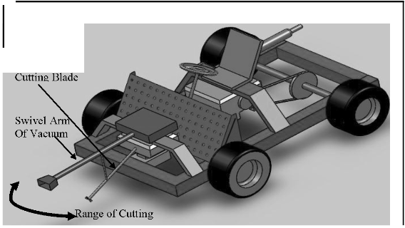
field. The design was completely changed due to some drawbacks which has been mentioned below.
Swivel Arm of
Figure 3.3 CATIA model of concept 1
3.2.1 Draw backs of the Prototype
• Motion control of the swivel arm of cutting blade and vacuumnot synchronized with vehicles movement.
![]()
Combined threshing and harvesting Page14
oventr:v
![]()
n1vers1£Y M.S Ramaiah School of Advanced Studies -Postgraduate Engineering and Management Programme (PEMP:
• Range of Cutting varies due to swivel mechanism vacuumnot synchronized with vehicles movement.
• Skill requirement for handling the swivel operation for straight line cutting of crop.
• Straw collection is not possible as per the design.
• Straw gets completely thrown into the field due to the cutting technique adopted so additional labour required for cleaning the field.
• Possibility of Vacuum pipes getting blocked by foreign particles (Plastics, papers etc.)
• Cost of the Equipment is high.
3.3 Concept design 2
Figure 3.4 Sketch of concept design 2
The second design was based on an idea of an attachment being fixed onto a tractor. This attachment should be capable of drawing the power from the tractor for its operation and should be capable of harvesting and threshing at the same time as shown in fig. 3.4.![]()
Combined threshing and harvesting PagelS
oventr:v
![]()
n1vers1£Y M.S Ramaiah School of Advanced Studies -Postgraduate Engineering and Management Programme (PEMP:
3.4 Concept of cutting mechanism with vacuum roller
Figure 3.5Sketch of cutting mechanism with vacuum roller concept
This concept design 2 consists of vacuum roller for carrying the cut crop and cutting blades at the bottom having to and fro motion for cutting of the crop. The second image shows conveyer used for carrying of the crop and a secondary roller at the bottom for threshing as shown in 3.5 and
3.6.
3.5 Final Concept Modeled in Solid Works

Figure 3.6 Final concept
![]()
Combined threshing and harvesting Page16
oventr:v
![]()
n1vers1£Y M.S Ramaiah School of Advanced Studies -Postgraduate Engineering and Management Programme (PEMP:
4.1 Design Details
Chapter-4
![]()
Design and Modeling
For manufacturing of combined finger millet harvesting and threshing attachment, after arriving to the final concept design the 3D assembly design along with the individual part drawing with dimensioning and bill of materials are generated in first angle projection using Solid Works V12 and AutoCAD- VlO software. While designing the following considerations are made:
• The height, width and length of the attachment are fixed to (500 x 700 x 990) mm as the attachment is to be compact and of less weight.
• Wherever it's possible standard elements are used in the design in order to reduce the cost and to make the assembly as simple.
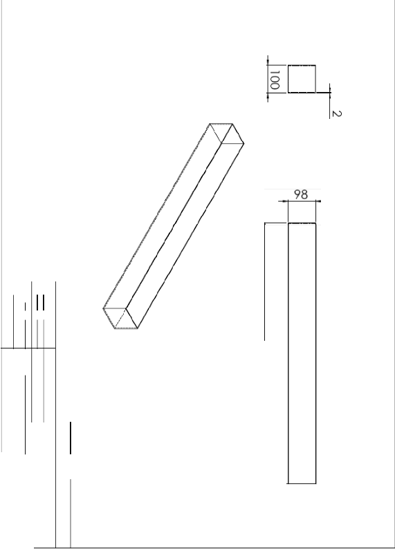
• The frame is made of rectangular cross section standard tube selected from IS series having a width of 70mm, with a height of 30 mm and thickness of 2.6mm.
• For the conveyor roller and the threshing roller the standard seamless steel tube of diameter
1OOmm is used.
• Mostly fasteners (screws, bolts and nuts) are used for assembling wherever it's possible for easy dismantling, maintenance and to carry out correction works.
• For conveyor belt food grade PVC standard belt is selected.
• For vacuum roller AC/DC 230v standard motor with a vacuum pressure of lOOOmmHg is selected and fixed in the attachment.
• In order to transmit power to the various mechanisms like conveyor roller, threshing roller, cutting mechanism etc, the shaft is keyed and pulleys are fixed.
• For transmission of power "B2" type pulley and belts are used in the attachment.
• A gear box with bevel gears is used to transmit the power for cutter blades along with a slider crank mechanism to convert rotary motion from the input to reciprocating motion of the cutter.
• The containers for grain collection and the straw collection designed in such a way that can be easily detached from the attachment whenever it is filled.
• Provision for adjusting height of the cutting mechanism is given. Also easy remove and installing of cutting mechanism and also to adjust the height of ground clearance as per the field condition.![]()
Combined threshing and harvesting Page 17
oventr:v
![]()
n1vers1£Y M.S Ramaiah School of Advanced Studies -Postgraduate Engineering and Management Programme (PEMP:
4.2 Modeling
![]()
![]()

The entire modelling of the finger millet harvesting and threshing mechanism is carried out using Solid Works-V12 work bench as it is also possible in the software to convert modelling file into a Para-solid file for transferring the model to ADAMS for kinematic analysis. And the detail manufacturing drawing with dimensions and bill of material is generated using AutoCAD- VlO software. The model consists ofthe three sub assembliesshown below.
Combined finger millet harvesting and threshing assembly
r
Vacuum operated Conveyor assembly Threshing assembly roller assembly
Figure 4.1 Final assembly
The image of the finger millet harvesting and threshing attachment after rendering is shown in the Fig4.1.![]()
Combined threshing and harvesting Page18
oventr:v
![]()
n1vers1£Y M.S Ramaiah School of Advanced Studies -Postgraduate Engineering and Management Programme (PEMP:
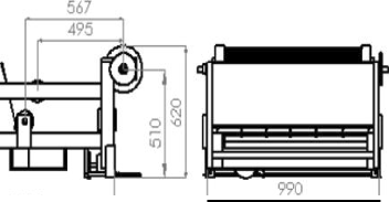
l()X)
![]()
All dimensions are in mm
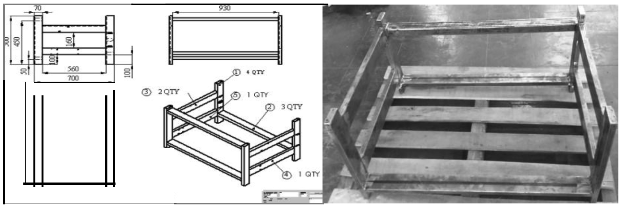
4.3 Frame
Figure4. 20verall dimensions of assembly
The frame is the element in which all the sub assemblies i) vaccum operated roller and ii) conveyor iii) threshing unit is assembled. The frame is made up of mild steel tube having a rectangular cross section with dimensions of (70 x 30 x 2.6)mm selected from IS series. While selecting the section, the following considerations are made:
• Less weight to high stiffness.
• Easy weld ability.
• Easy machinability
• Low cost
The various manufacturing process involved in the frame is cutting the rectangular section tube to the required length using metal slitting saw, drilling holes to provide relief holes for the bolts and the major operation is welding to fix the various parts togeather regidly. The Fig 4.3 shows the the manufacturing drawing and the frame after manufacturing.![]()
Combined threshing and harvesting Page 19
oventr:v
![]()
n1vers1£Y M.S Ramaiah School of Advanced Studies -Postgraduate Engineering and Management Programme (PEMP:
l"ll=f::F======tR
Note, AI the tvbe are ]():)Q(bQ 6
Figure4. 3 Frame
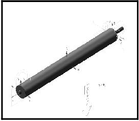
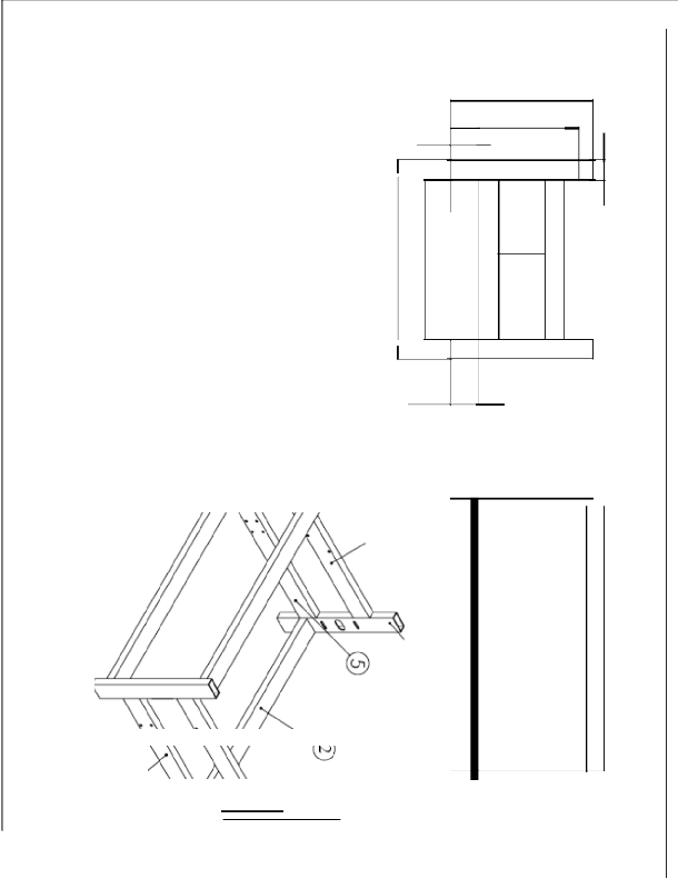
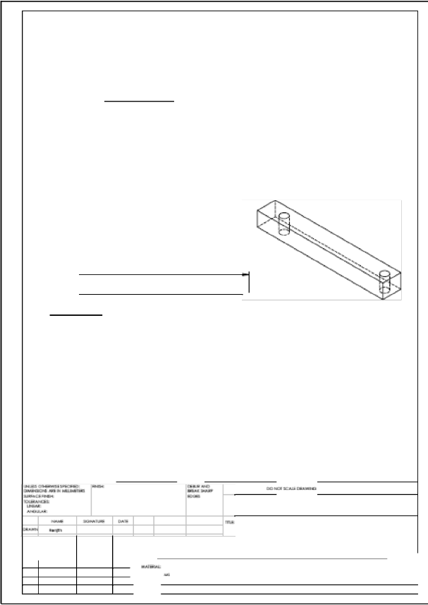
4.4 Vacuum and roller assembly
The vacuum roller consist of internal stationary vacuum suction pipe which is inclined to the angle of 45° so as the vacuum pressure will be generated within the angle. The vacuum suction stationary pipe is covered by the pierced sheet rolled on it a rotating drum , which is allowed to rotate freely so that when the cutting takes place due to the vacuum pressure the straws will be carried by holding on the rotating drum and the rotating drum rotates the straws are held by vacuum pressure and carried finally when the drum rotation angle reaches the extreme limit of the vacuum pressure the straws are dropped on to the conveyor as indicated in the arrow in the Fig4.4. The manufacturing processes includes i) vacuum stationary pipe - PVC pipe cutting and joined with admissive ii) pierced sheet- rolled and welded to the end caps iii) end caps -turned and bored to the dimension.
Figure 4.4Vacuum roller
![]()
Combined threshing and harvesting Page20
oventr:v
![]()
n1vers1£Y M.S Ramaiah School of Advanced Studies -Postgraduate Engineering and Management Programme (PEMP:
5.1 Vaccum mechanism
![]()
Chapter-S Mechanisms, Calculations and Manufacturing
![]()
Figure 5.1 Vacuum mechanism
Vacuum Technology is based on the mechanism in which air is removed from a system to sub atmospheric pressure. Particles move from high atmospheric pressure to low atmospheric pressure. In the current system vacuum motor is used to generate the vacuum so that air is removed from the perforated drum causing pressure difference within the drum resulting in crop sticking
onto drum.
Table 3 Vacuum description and range
Vacuum Description | I Range I |
Low vacuum | 25 to 760 Torr |
Medium vacuum | 1o·3 to 25 Torr |
High vacuum | 10-6 to 10-3Torr |
Very high vacuum | 10·9 to 10-6Torr |
Ultrahigh vacuum | 10"12to 10·9 Torr |
Extreme Ultrahigh vacuum | below 1o-12Torr |
A universal Motor is selected so it can be connected to AC current or DC Current (230 V Single Phase).A medium pressurevacuum motor having a vacuum pressure of 1.3torr (1 Torr
=760mmHg) is used for the current system. The basic selection of a vacuum motor is based on the suction force rating of the motor. The suction force should be more than the total force exerted by the crops downwards, when the crop is held by the perforated sheet of the vacuum assembly.
5.2 Conveyor mechanism
The conveyor is the other mechanism which is provided to carry the straws to the threshing mechanism after cutting. The rollers are placed at the angle of 15° so as the effective transfer ofthe straws takes place and also to provide the threshing mechanism and to place the collecting bins for straws and grains are placed below the conveyor which in tum reduces the length of the attachment. For his mechanism two rollers are used, one roller acts as driver which is connected to![]()
Combined threshing and harvesting Page21
oventr:v
![]()
n1vers1£Y M.S Ramaiah School of Advanced Studies -Postgraduate Engineering and Management Programme (PEMP:
the pulley and the other roller is driven by the driver using conveyor belt. In this assembly for conveyor rollers seamless steel tubes of standard diameter 1OOmm is used and the standard conveyor belt PVC food grade conveyor belt is selected and used. The manufacturing processes includes i) end caps -turned and welded to the conveyor roller ii) bearing support plates -hole is bored to fix the bearing and holes are drilled to fix the plate in the frame using bolts. The Fig5.2 shows the conveyor assembly.
Figure 5.2 Roller and conveyor mechanism
5.3 Threshing mechanism
Threshing mechanism is provided to separate the grains from the straws the mechanism consists of threshing roller which is covered by the rubber material to avoid damaging of the grains and by friction to transfer the straws to the collecting bin threshing mechanism consist of threshing plate, the clearance between the threshing plate and the threshing roller is gradually reduced to 1.5 mm as the finger millet diameter is around 1. 5mm. The series of holes are provided in the threshing plate below the holes the grain collecting bin are provided through the holes the grains gets collected into the bin. In order to strengthen the threshing plate the stiffeners are provided to the threshing plate. For the threshing roller a standard seamless steel tube of diameter lOOmm is used. The end cups are turned and welded to the roller, the bearing support plates are bored and bearings are fixed and relief holes are drilled to clamp the support plate to the frame. The Fig5.3 shows the threshing attachment.![]()
Combined threshing and harvesting Page22
oventr:v
![]()
n1vers1£Y M.S Ramaiah School of Advanced Studies -Postgraduate Engineering and Management Programme (PEMP:
Figure 5.3Threshing mechanism
5.4 Harvesting mechanism
The harvesting (cutting) mechanism consists of two cutting blades the fixed blade and moving blade. The fixed blade is the stationary blade which remains stationary while cutting takes place and the moving blade slides on the fixed blade by the slider crank mechanism and cuts the straws a
bevel gear box is used to transmit the power to 90°
Rocker
Arm
Stationary cutter
Movable cutter
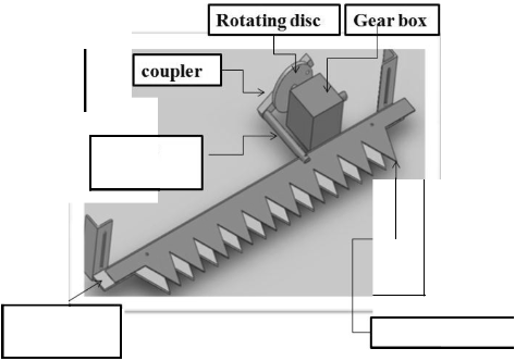
Figure 5.4 Cutting blade mechanism
![]()
Combined threshing and harvesting Page23
oventr:v
![]()
n1vers1£Y M.S Ramaiah School of Advanced Studies -Postgraduate Engineering and Management Programme (PEMP:
5.4.1 Mechanism of harvesting
For the motion of cutting mechanism for blades a simple 'Slider-Crank Mechanism' is employed which has fixed blade, movable blade, rotating disk, rocker arm and coupler in which the fixed blade and moving blade has prismatic joint, coupler and rocker arm has revolute joint, the coupler and rotating disk has revolute joint and the rocker and moving blade has fixed joint. This mechanism is used to convert rotary motion into the reciprocatory motion. This can be achieved by mounting the coupler off set from the center of rotating disk as shown in the Fig5.5.
Crank and Slider
Figure 5.5Slider Crank Mechanism
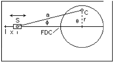
In the Fig5.5 the circle represents a rotating disk of thickness 't' and radius 'R'. CS represents the length of the coupler positioned offseted in rotating disk at a distance 'r'. When the coupler and the dotted line indicating distance 'r' gets collinear at one end the minimum stroke and in the other end maximum stroke is achieved and thus the displacement'S' takesplace.
For this mechanism, the power for driving the cutting mechanism is transmitted from the engine with the help of the pulley mounted on the external shaft and a bevel gear box is used to power obtained from the pulley in 90° and the suitable diameters of the pulley is used in the cutting mechanism to ensure the veloccity of blades in cutting mechanism. The belt used in this mechanism is the V-Belt oftype 'B' for the pulleys.
5.4.2 Slider Crank Mechanism for cutting
The pulley mounted at the cutting mechanism is rotating about the horizontal axis parallel to the engine axis, in order to transmit power rotating disk the power has to be transmitted to the perpendicular axes for which the bevel gear box is used. In thecutting mechanism, the standard bevel gears box which are present in the machine toolsis used.
For the above bevel gear arrangement, one bevel gear is coupled to the shaft of the pulley placed at the cutting mechanism and the other bevel gear (having the axis of rotation intersecting the previous one at 90 o was coupled to the center ofthe circular plate as shown in Fig5.6.![]()
Combined threshing and harvesting Page24
oventr:v
![]()
n1vers1£Y M.S Ramaiah School of Advanced Studies -Postgraduate Engineering and Management Programme (PEMP:
5.5 Calculations
Figure 5.6Bevel Gears box of machine tool
![]()
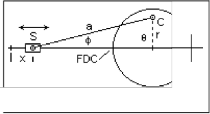
Themaximum displacement of the cutting blades and the velocity of the blades are calculated.The distance by which the slider moves per stroke is given by the following relation.
x = a(l- cos <p) + r(l -cos 0)
![]()
Crank and Slider
Figure 5.7Slider Crank Mechanism
Where, xis the linear displacement
ais the length of the connecting rod ris the length ofthe crank
<p is the angle subtended by the connecting rod with the horizontal.
0 is the angle subtended by the crank with the horizontal.
![]()
Combined threshing and harvesting Page25
oventr:v
![]()
n1vers1£Y M.S Ramaiah School of Advanced Studies -Postgraduate Engineering and Management Programme (PEMP:
The above mentioned relation was used to determine the distance as shown below:
x = a(1- cos <p) +r(1- cos 8)
= 0.304(1 -cos 30) + 0.0762(1 -cos 30)
= 0.0407 + 0.01020
= 0.0509 m or 50.9 mm
From this, it can be seen that the upper blades will move by a distance of 50.9 mm for one full rotation of the disc. The speed of the cutter is determined using the following procedure:
V = r*ro
Where,r is the radius ofthe crank
ro is the angular velocity in rps.
v = 0.1524*0.0762
= 0.0116 m/s.
From this, the speed ofthe cutter is deduced to be 0.0116 m/s or 11.6 mm/s.
5.6 Calculations of belt drive
As the rpm of the engine is 2100 in order to obtain various rpm at the various mechanism like vacuum roller, threshing roller, conveyor roller, etc it is required to select the proper diameter pulley and also in between intermediate pulleys are used to reduce the diameter of pulley and to obtain the rpm as shown in the Fig().
Figure 5.8 Combined belt drive
The diameter and the rpm of pulley are found using the velocity ratio formula:
Nt Dz
-=-
Nz D1![]()
Combined threshing and harvesting Page26
oventr:v
![]()
n1vers1£Y M.S Ramaiah School of Advanced Studies -Postgraduate Engineering and Management Programme (PEMP:
Were,
N 1 =rpm of driving pulley.
Nz =rpm of driven pulley.
D1 = diameter of driver pulley.
Dz = diameter of driven pulley.
The various diameter of pulleys are found and fixed in the attachment as shown in the FigS.8.
Figure 5.9 Power transmission using belt drive
5.7 Kinematics analysis
The kinematics analysis 1s carried out using the ADAMS software through which the motion ofthe blades in the cutting mechanism is verified and also the forces acting on the bearing due to the rotation of the rollers are found and the bearings are selected based on the result obtained. The FigS.11 shows the graph of the force acting on the bearing in Newton and the FigS.l3 shows the graph of displacement length of the blade in mm.
Figure 5.10 Model of roller to obtain forces acting on roller
![]()
Combined threshing and harvesting Page27
oventr:v

![]()
n1vers1£Y M.S Ramaiah School of Advanced Studies -Postgraduate Engineering and Management Programme (PEMP:
§- 11 6.5 I
I I I
117.0
Force act1ng on threshing roll er
------------------- - -'----------------.
c
11 6.0 1--- --- - == == ==- -- ----- =±== ==±= -
c
· + .. + ..
(])
..0 11 5.5
0
(])
(.)
0 11 5.0
+ ..
+ ..
+ ..
+ ..
114.5 +--- --- -- --- --- -- ------ --- --
0.0
1.0 2.0 3.0
T1mP 1ni sec:l
Figure 5.11 Forces acting on roller bearings
4.0
5.0
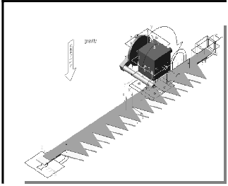
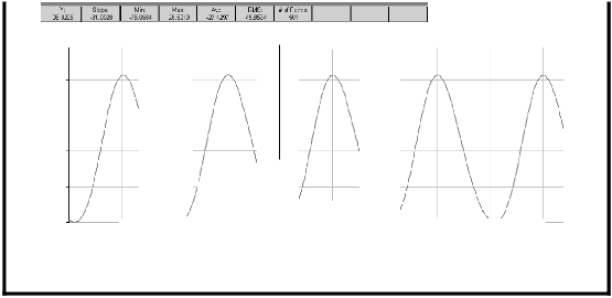
Figure 5.12 Model of cutting mechanism to obtain blade velocity
'1".52
E
E
E E
Moving blade displacement
50.0.--------------- --------------------
(]) 0.0 ""0
ro
:0
E
""0
(])
-
-50.0 + .. I
<1.>
0c ro (;)
0
+ ..
-100.0
0.0 1. 0 2.0 3.0 4.0 5.0
T1me (sec)
Figure 5.13 Displacement of cutting blade
![]()
Combined threshing and harvesting
Page28
oventr:v
![]()
n1vers1£Y M.S Ramaiah School of Advanced Studies -Postgraduate Engineering and Management Programme (PEMP:
5.8 Various steps in manufacturing
![]()
Combined threshing and harvesting Page29
oventr:v
![]()
![]()
n1vers1£Y M.S Ramaiah School of Advanced Studies -Postgraduate Engineering and Management Programme (PEMP:
Chapter-6
Fabricated Combined Harvesting and Threshing Attachment
![]()
6.1Final finished project of combined harvesting and threshing attachment
Figure 6.1Finished combined harvesting and threshing attachment
6.2 Specifications of the vehicle
• Weight--- 140 kg (Approx)
• Overalllength---1000 mm
• Overall width---1000 mm
• Height ---500 mm
• Cutting width---1000 mm
• Engine type--- Needle vibrator engine
• Engine fuel---regular petrol
• Maximum power- 1.2kw at 2100 rpm
![]()
Combined threshing and harvesting Page30
oventr:v
![]()
n1vers1£Y M.S Ramaiah School of Advanced Studies -Postgraduate Engineering and Management Programme (PEMP:
6.3 Advantages
The finger millet harvesting and threshing has following advantages:
• The attachment is compact and can be easily attached to the agricultural farm machineries.
• Range of Cutting is designed for the bed width of finger millet plantation.
• Straw collection and the grain collection is possible by the attachment.
• Possibility of Vacuum to use as blower for cleaning the vaccum roller while it gets blocked
• Finger Millet crop height is not the problem for this attachment it is possible to harvest different crop heights.
• Ground Clearance of the blades can be varied by the height adjuster.
• Cutting force on the blade is reduced by the vaccum pressure as the vaccum roller pulls the crop and in tension cutting takes place.
6.4 Scope for Future work
• Power transmission to the attachment from the tractor to be incorporated.
• The storage capacity of grains and straws to be increased
• The size and the weight of the attachment has to be reduced
• The number of pulleys used for the power transmission has to be reduced
• Intermittent heaters can be incorporated before threshing.![]()
Combined threshing and harvesting Page31
oventr:v
![]()
n1vers1£Y M.S Ramaiah School of Advanced Studies -Postgraduate Engineering and Management Programme (PEMP:
References
![]()
[1]Dr. ShailajaHittalmani, "Developmentof high yielding, disease resistant, drought tolerant Finger millet", University of Agricultural sciences,GKVK, Bangalore-560 065, India, shailajah_maslab@rediffmail.com
[2]R. S. Khurmi, "A text book of machine Design"
[3]A. Sreenatha, "Fingermillet Harvesting and Threshing inKarnataka: A Case Study",Research Associate, Division of Agricultural Engineering, UAS, GKVK, Bangalore-560065, Karnataka, India.
[4]Anonymous, 2010. http://dacnet.nic.in/extension/document/chapter/66.htm [5]Jayapalaiah, G.P, 2000, "Prototype Thresher for Finger Millet", Unpublished M.Sc. Thesis University of Agricultural Sciences, Bangalore
[6]ChowdeGowda, M., Sreenatha, A., Ramya, H.N. AndJaymala, G.B., 2010. "Estimation of Energy Requirement for finger millet (Eleusine G.)Cultivation in Karnataka (India)". International Journal of AppliedAgricultural Research, 5(1) 1-8
[7]0jha, T.P and Devnani1987, Status of harvesting machinery in India -aCountry report, "Regional work shop on Design and Development of harvesting and Threshing Equipment" ,IARI, New Delhi, October 4-14.
[8]ChandrakantappaKammar, Batagurki.S.B and Krishnappa.N, 2001, "Effect of Different Threshing methods on mechanical Damage and germination of finger millet",CurrentResearch [9]http://www.qfdi.org/what_is_qfd/what_is_qfd.htm
[10]"Millets", Millet Network oflndia- Deccan Development Society- FIAN, India
![]()
Combined threshing and harvesting Page32
oventr:v
![]()
n1vers1£Y M.S Ramaiah School of Advanced Studies -Postgraduate Engineering and Management Programme (PEMP:
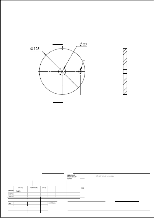
Appendix- Part Drawings
![]()
tv
0
0
n98
,v_
![]()
Combined threshing and harvesting Page33
oventr:v
![]()
n1vers1£Y M.S Ramaiah School of Advanced Studies -Postgraduate Engineering and Management Programme (PEMP:
![]()
qJJ 1 11iiP
' •d
I I
r
-.o
N
+ 0
+
jj + m
....
I
' a
cc ti
0 I
X
' N
ll
![]()
Combined threshing and harvesting Page34
oventr:v
![]()
![]()
n1vers1£Y M.S Ram aiah School of Advanced Studies -Postgraduate Engineering and Management Programme (PEMP:
'\1\1
1o:JJ
19) 600 150
50 _.-
l7 --
\VV}IVWW\N -
A
100 40
[1.9J]
100
cO
I v.
v.
DEJAJL A
00 SCALE 1 :5
L [ 100D } _I
QTY; O
1121¥...JfoCK»>QQ:M.'II -
...,......I..H..>..,.
I:X:tCIIEAUI 1 ..
"."..".."..". ""- ..,...
.............: - -t-

.,....
,"_"'"""
.....
,..y, ......
lbtm blade
:a. ....""'"'"' IO'MIIIC1 M
-· ·· 1 ...... ,.,.,
![]()
Combined threshing and harvesting Page35
oventr:v
![]()
n1vers1£Y M.S Ramaiah School of Advanced Studies -Postgraduate Engineering and Management Programme (PEMP:
z
0 30
.CD.
)>
-+ "J" CD
-..;
CD
0
-+
0
500
450
50
I
I I I r c:
w •.
VI 160
0 0\
0 0 .
(Q
c
-..;
c-+
0""
CD
0
-..;
CD
'-J
0
><
0
><
N ,0
()-.
100
1 0 0 0
D
---i
-<
.j::.
,0
.I
I w
I
I ,0
I
![]()
ttl
0
IQ,
D
=<
<J
![]()
![]()
Combined threshing and harvesting Page36
oventr:v
![]()

n1vers1£Y M.S Ramaiah School of Advanced Studies -Postgraduate Engineering and Management Programme (PEMP:
, 175 .,
(/)'}!) o:r-
- - -31-
,..;'"'-
,a..u.............,.......,"""""""-'· - &..,a.&.ll.';.l.i.i.C.}...
CC:HCII:ICI.U! 1 ..-
I =.. I
I I ............. ,.., ......
.,...,
.........,
::A "'"'"""" ,...._ cyl sup M
_I -·
""""--" 11M.I I Clio I
![]()
Combined threshing and harvesting Page37
oventr:v
![]()
n1vers1£Y M.S Ramaiah School of Advanced Studies -Postgraduate Engineering and Management Programme (PEMP:
w
A
010
A
:I ..eN
I:».. :M-11N
........,.._-K,.,.
-
L--L------ ---- --- -·
50
-1 1.. 10
S ECTlONA-A
flywhl
![]()
Combined threshing and harvesting Page38
oventr:v
![]()
n1vers1£Y M.S Ram aiah School of Advanced Studies -Postgraduate Engineering and Management Programme (PEMP:
r· 930 .I
- \\ . ;
'f$f
" oJ:?<.

m.aa IIH)
........""...... ..,....,
1 .. _...,., ....... .....
.
CIC:JoiCR:IC:AIJIU.. , ......,.
c.&"D
............,.
::& - .,..,..1«1 guide [plate -
-·
·· :lrMIJII r» I I
![]()
Combined threshing and harvesting Page39
oventr:v

![]()
n1vers1£Y M.S Ramaiah School of Advanced Studies -Postgraduate Engineering and Management Programme (PEMP:
120
50
_:::zd
15
-- t: ·--t J
e e.
-::::z::::;
Q..,.,
e
A ,..... SECTION A-A
." ' ..:I
"""""""
- ---+-----4------·-
Ciil,
-4--
WFrri ------4------+-- -- ---- ----
=A -------r------+-MM holder
------ ---- ---"""""''
"""""""'.. I
![]()
Combined threshing and harvesting Page40
oventr:v
![]()
![]()
n1vers1£Y M.S Ramaiah School of Advanced Studies -Postgraduate Engineering and Management Programme (PEMP:
II
8 II II II ii ii II II
22.50
I i'
1..1
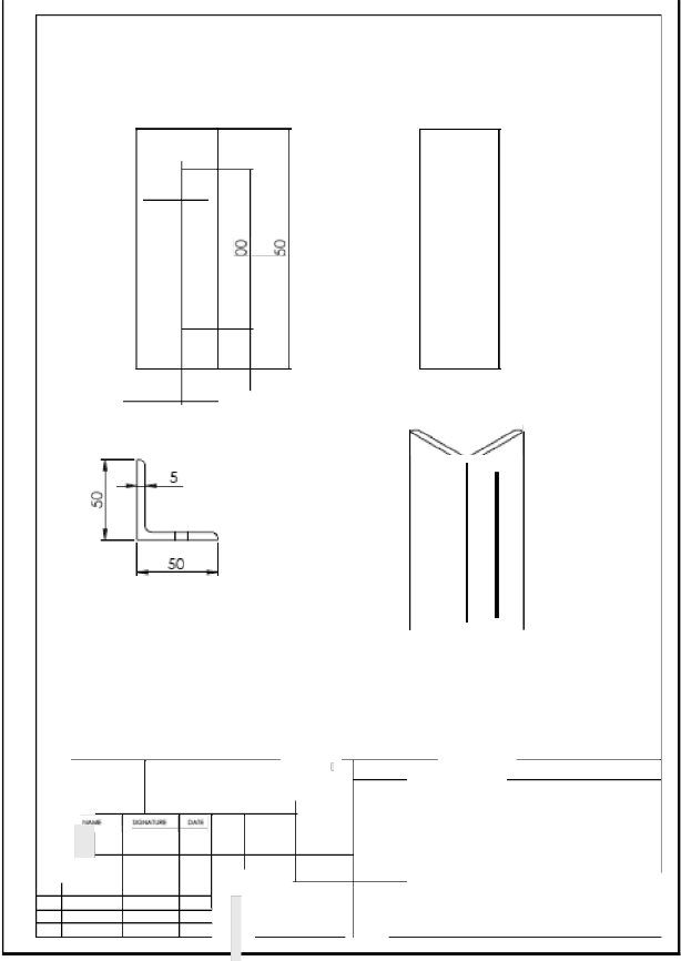
Note :STD. langle 50x50x5 / QTY:02
=:u w..:;=!a ..ac
'".".".."."..".
l.:.a..!....H..C..:.·..
,....
rx: IC:II :lOW! ta:.w..c. 1 ...,..,.,
. ·- r----+--+--;----;--- ,
L angle
""""-----;-----r--+- ----+---
-.------r----+---r...-............. A4
-· --
i<=.W.. I
1.-11001 I
![]()
Combined threshing and harvesting Page41
oventr:v
![]()
n1vers1£Y M.S Ramaiah School of Advanced Studies -Postgraduate Engineering and Management Programme (PEMP:
w
2x ¢ lOiHRU
I
175 }
Cl !i ! iI
v ------ -----+---+---r-----r----_,
------ -----+-- -- -----r----_,
Md .------ -----+--
..,._,
L plate
![]()
Combined threshing and harvesting Page42
oventr:v
![]()
n1vers1£Y M.S Ramaiah School of Advanced Studies -Postgraduate Engineering and Management Programme (PEMP:
A .....I
I '

$I.._
870 J
SECilON A-A SCALE 1: 6
a t !_ILitMC>
cwJtai::INI .......liiU.Ii6-dG
'""""""..... .......
l=u
I I _,,..,.. ...... lou..
c.&"D
onYI:
.;:A. .....""""'-' """'*- roller tube A4
-· "'-"-'-"" JiMII 121
![]()
Combined threshing and harvesting Page43
oventr:v
![]()

n1vers1£Y M.S Ramaiah School of Advanced Studies -Postgraduate Engineering and Management Programme (PEMP:
-(¥
r
-<i3r
I
I
I I
I
I
I
I I
!
f'Q
JHI..,a ,I I :t-- - r.:.J..,..-_Mil,).
CC:ICI I ......_
- - -- '". I......
aN An.._......a..Mo;.tG
""""-->oL I
......:..a..U
-
Clil"D
"""""
...
.....,......_,
_,.
I:WDIC1
SUP FOIR BOX A4
" 1Joelkllat-1 I
![]()
Combined threshing and harvesting Page44
oventr:v

![]()
n1vers1£Y M.S Ramaiah School of Advanced Studies -Postgraduate Engineering and Management Programme (PEMP:
37.5
w
(/)25 THRU
.Qj. .------
-l!l"J
r 50
,- -
1..,./,). I I
I
r---
1--
r--
r--
'-- +----- !}- r--
0 I 1 2.5 \ 4 x f./) 8.5 THRU AU .L.I
75
q
.......,
-
""""""".....
.-....-.N. C> Oc: te:l JCAI.lo DkA.W'£1 1 -
IIXM
............,
- ,_...,., "" ...
.,._,
......
sup for rub roller
... -- """'""" A4
- .. I,_,,.,., I
![]()
Combined threshing and harvesting Page45
oventr:v
![]()
n1vers1£Y M.S Ramaiah School of Advanced Studies -Postgraduate Engineering and Management Programme (PEMP:
l30 l40
-tir---+------+
8
2 x (/J 5 THRU AL /
30 40
100
:Jte.!:'IID::PK2K Mac
CIW M'I!W
- - -·- =..... ·;
I .,....,.
I u.g
-:u.
=·
---
supp blk roler
-----L---- ---·
1 ._.,...,
![]()
Combined threshing and harvesting Page46
oventr:v
![]()

n1vers1£Y M.S Ramaiah School of Advanced Studies -Postgraduate Engineering and Management Programme (PEMP:
![]()
w
I
0
I
I
8 - --
I
I
09J thru
125
p I I ! i I I
......,:.-.:PioOOo:,_
I
..............,....
CC HICI EI.U! I ..........
I:::W..JH:IIaNI .w.................
:&I>M::Io ......
,..._
....ua.n"
I I
......
QU · su pp blk
:.:.A - -- A4
....... ""'"""'"'.. 1 .....,.,., I
![]()
Combined threshing and harvesting Page47
oventr:v
![]()
n1vers1£Y M.S Ramaiah School of Advanced Studies -Postgraduate Engineering and Management Programme (PEMP:
1000
125 750
(/)5 THRU
lOCI
66()
2x0&THRU
-
-"•••It· -
--r-----,_--;---;-----;------;
O......... - -----,-------r,---+-----+------ --r------;;
·-=&-------+------+----!-
top b ade
-· ·-----------------·-·---
----------
![]()
Combined threshing and harvesting
Page48