The architecture of a digital signal processor is optimized specifically for digital signal processing.
International Journal of Scientific & Engineering Research, Volume 4, Issue 12, December-2013 1922
ISSN 2229-5518
Development of Optimal Path Plan for Wireless Electronic Perceptible Assistant System In Known And Unknown Terrain
Akella S Narasimha Raju1, S N Ali Ansari2, Ch Karunakar3
Abstract-A description of EPAS system which is for independent navigating for visually impaired person in identified and unidentified environments has been presented in this paper. This system incorporates the GPS receiver to access the spatial data of local environment by the server to the user. According to available spatial maps of the environment the user can freely move around the map. For this system, the implementation of optimal path planning using D*lite algorithm, estimate the direction and orientation of the user moves has been discussed. Time to time new environment map is stored in the spatial database. The database gives the fast information response to users using this D*lite algorithm when the path is revisited. In addition to this, the system has been established the ZigBee nodes for the home environment. According to ZigBee nodes, user can aware of the home environment using the server. The system gives the position, location and orientation of information to the server. Observations can be recorded for each and every movement of the user by sitting behind the server and monitoring the user’s movement by using specialized software which was already incorporated in the system, and user can also perceive the above mentioned information through audio signals. The head height vision sensor and foot level proximity sensors, perceive the information of the obstacle through the audio cues.
—————————— ——————————
1.INTRODUCTION
lindness is the condition of lacking visual perception due
have been developed to describe the extent of vision
This system, is a combination of Electronic Travel Aid (ETA), Electronic Orientation Aid (EOA) and Position location Device
EPAS)[1]. This system can be simply implemented by making
IJSER
to physiological or neurological factors. Various scales
loss and define blindness. Total blindness is the complete lack of form and visual light perception and is clinically recorded as NLP, an abbreviation for "no light perception." Blindness is frequently used to describe severe visual impairment with residual vision. According to National Federation for Blind (NFB) observation, worldwide more than
160 million people are visually impaired with 37 million to be
blind.
Several of these people use the white cane, generally used as travel aid for the blind. This is simply a mechanical device used to spot obstacles on the ground, rough surfaces, holes, steps. The cost-effective white cane is lightweight and tiny and it can be folded and slips into a pocket. The primary problem with this device is that users must be trained for longer periods. In addition, the white cane requires the user to keenly scan the small area ahead of him/her. The white cane is also not suited for detecting potentially dangerous obstacles at head level.During the past decades, various researchers have introduced devices that apply sensor technology to progress the blind users mobility in terms of safety and speed. Examples of these devices, Electronic Travel Aids (ETA’s) - devices that convert information about the environment that would normally be relayed through vision into a form that can be communicated through another sensory modality.
Electronic orientation aids (EOAs)-Devices that provide orientation prior to, or during the travel. They can be external to the user and/or can be carried by the use.
Position locator devices (PLDs- which include technologies like
GPS.
(POD) named as ―Electronic Perceptible Assistance System(
the user carry both the NAVI [3] and GuideCane[4] at the same time. The main aim of our system is to create a wireless system that is easy to carry and help the blind to navigate easily on their own. This system gives the information of the obstacle from head height to foot level; hence, the system follows ETA guidelines [2]
Therefore, the authors propose to build wireless ZigBee network for closed environment and connect with Bluetooth. The Global Position System (GPS) for position and location and also select the optimal path algorithm can be connected to the user to navigate smoothly in known and unknown environments. It also includes the headphones and mike to user who can receive and inform messages in the form of audio signals. Suppose the user wants any information about environment, the system can provide the same.
3. IMPLEMENTING CONCEPTS FOR EPAS
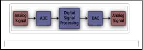
Signal processing has been used to transform or manipulate analog or digital signals for a long time (Fig 1). One of the most frequent applications is obviously the filtering of a signal. Digital signal processing has found numerous applications, data communications, speech, audio, image, video biomedical signal processing, instrumentation and robotics.
Digital signal processing algorithms typically involve a large amount of mathematical operations to be performed quickly and repetitively on a series of data samples. Signals (perhaps from audio or video sensors) are constantly transformed from analog to digital, manipulated digitally, and then transformed back to analog form.
IJSER © 2013 http://www.ijser.org
International Journal of Scientific & Engineering Research, Volume 4, Issue 12, December-2013 1923
ISSN 2229-5518
Most general-purpose microprocessors and operating systems can execute DSP algorithms successfully, but are not suitable for use in portable devices such as mobile phones and PDAs because of power supply and space constraints. A specialized digital signal processor, however, will tend to provide a lower-cost solution, with better performance, lower latency, and no requirements for specialized cooling or large batteries.
The architecture of a digital signal processor is optimized specifically for digital signal processing.
Fig 1: Analog to Digital conversion using using DSP
A field-programmable gate array (FPGA) is an integrated circuit designed to be configured by a customer or a designer after manufacturing—hence "field-programmable". The FPGA configuration is generally specified using a hardware description language (HDL), similar to that used for an application-specific integrated circuit (ASIC).Contemporary FPGAs have large resources of logic gates and RAM blocks to implement complex digital computations. As FPGA designs employ very fast IOs and bidirectional data buses it becomes a challenge to verify correct timing of valid data within setup time and hold time. FPGAs can
Fig 2: Proposed Image Processing Methodology
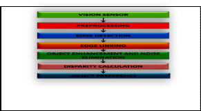
The image processing involves five stages; preprocessing, edge
detection, edge linking, object enhancement and noise
elimination and object preference procedures. Image is captured from the vision sensor and used as input image.
Preprocessing:
The input image is resized to 256 x 256 pixels and contrast-
stretching technique is applied to each color component of the resized image. Image resizing is prepared as to facilitate quicker processing.
Edge Detection:
From the enhanced image, edges are extracted. The goal of edge
detection is to provide structural information about the object boundary. In this work, region inside the closed boundary is considered as an object. Hence, by extracting edges in the image, object‘s feature can be obtained. In this work, the preprocessed color image is separated into three components (R, G and B components) and Canny Edge Detector is applied to each of the color component. The Canny Edge Detector Algorithm consists
IJSER
be used to implement any logical function that an ASIC could
perform.
Field-programmable gate arrays (FPGAs) are on the limit of revolutionizing digital signal processing in the approach that programmable digital signal processors (PDSPs) did nearly two decades ago. Many front-end digital signal processing (DSP) algorithms, such as FFTs, FIR or IIR filters, to name just a few, previously built with ASICs or PDSPs, are now most often replaced by FPGAs. Modern FPGA families provide DSP arithmetic support with fast-carry chains (Xilinx Virtex, Altera FLEX) that are used to implement multiply-accumulates (MACs) at high speed, with low overhead and low costs
The main purpose of blind navigation is to support the blind people to navigate freely among obstacles by providing them the position, size and distance of the obstacles. The obstacles in the captured image should be given more importance compared to that of background. Hence, it is crucial to develop a perceptible assistance kit such that the blind user understands the environment in front of him with minimum efforts.
The essential task of the image processing in EPAS is to identify and highlight objects in the scene in front of blind user and communicate this information in real time through auditory cues. The term ‘real time‘ is referred to the sampling of the information of the scene in front at the rate of 24 image frames(video) per second. In EPAS, duration of sound produced from each sampled image is equal to less than one second. therefore, the computational time for image processing has to be in milliseconds so that the processing of new image and sonification can be carried out during the transmission of previous image‘s sound. Fig 2. Illustrates the block diagram of proposed image processing stages for this ETA
of following steps:
• Noise reduction: The Canny edge detector is susceptible to noise present in raw unprocessed image data, it uses a filter based on a Gaussian (bell curve), where the raw image is convolved with a Gaussian filter. The result is a slightly blurred version of the original which is not affected by a single noisy pixel to any significant degree.
• Finding the intensity gradient of the image: An edge in an image may point in a variety of directions, so the Canny algorithm uses four filters to detect horizontal, vertical and diagonal edges in the blurred image.
• Non-maximum suppression: Given estimates of the image gradients, a search is then carried out to determine if the gradient magnitude assumes a local maximum in the gradient direction. From this stage referred to as non-maximum suppression, a set of edge points, in the form of a binary image, is obtained. These are sometimes referred to as "thin edges".
• Double thresholding: Potential Edges are determined by thresholding
• Edge tracking by hysteresis: Find edges determined by suppressing all that are not connected to very strong edge
Edge linking
This is method of assembling edges in the image to form a closed edge. Discontinuity in edge is due to different reasons such as insufficient lighting, geometric distortion and image resizing effect. To connect the edge fragment in the image, edges are scanned in vertical and horizontal direction If an edge is present at the specified location and no edges exist between located edge pixels, this non-edge pixel is identified as a candidate edge. The two edge pixels are linked by the candidate edge pixel thus forming an edge link. By undertaking the proposed edge linking procedure, closed boundary of objects can be extracted.
Object Enhancement and Elimination of Noise
IJSER © 2013 http://www.ijser.org
International Journal of Scientific & Engineering Research, Volume 4, Issue 12, December-2013 1924
ISSN 2229-5518
The object‘s region pixels have to be enhanced to high intensity and the background‘s pixels to low intensity. This stage is crucial prior to sonification procedure. During the sonification, the image with pixels of high intensity will generate sound of higher amplitude. On the other hand, image with pixels of low intensity will generate sound of lower amplitude. Stereo sound patterns set of pixels with high intensity in the dark background is easy to identify than the low intensity over bright background. If the image is transferred to sound without any enhancement, it will be a difficult task to understand the sound. With this consideration, the object region is enhanced to high intensity. A ‘flood- fill‘operation is carry out for the object enhancement. Through experimentation, it is observed that not all edges in the image are object boundaries. These extra edges are considered as noise. Noise has to be eliminated so that correct properties of object can be measured. Morphological operations, erosion and dilation are employed to eliminate noise in the image.
Disparity Calculation
Disparity forms the basic criteria for stereo vision. Once the
disparity is determined then the depth can be calculated. In order to calculate the disparity, correspondence or matching of two images has to be undertaken. Area based stereo matching is performed over the stereo image pair.
Object Preference:
The main objective of object preference task in this work is to
identity objects in the image in accordance to human visual preference. In human vision system, a visual consideration is
given on an interested object and the other areas are given less
widely deployed in wireless control and monitoring applications. Low power-usage allows longer life with smaller batteries.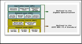
Fig 4. Shows the high-level software architecture of ZigBee.
Fig 4: Architecture of Zigbee
PHY LAYER
IEEE 802.15.4 defines three operational frequency bands: 2.4
GHz, 915 MHz and 868 MHz. Other tasks that the PHY layer is
in charge of are:
• Activation and Deactivation of Radio Reciever.
• Receiver Energy Detection (RED)
• Link Quality Indication(LQI)
MAC LAYER
The MAC layer, defined in IEEE 802.15.4, provides an interface between the physical layer and the higher layer protocols. It
handles all access to the physical radio channel employing the
IJSER
consideration. By assigning equal preferences to all objects, blind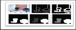
user will have confusion in understanding the features of object. In this work, the central of image pixel area is called as iris area. In human vision system, the object of interest will be usually at the centre of sight (in this work denoted as iris area). If the object is not within the centre of sight, the object can be brought to the centre by turning the head or occurrence in iris area and sizes. Object in the centre is more important for collision free navigation. But in EPAS, object is undefined, uncertain and time varying. This is due to the constant shifting of the headgear- mounted orientation by the blind people. To resolve this uncertainty, fuzzy logic is applied.
Fig 3: Image processing steps
3.3. Wireless communication concepts
A. ZIGBEE
ZigBee is a specification for a suite of high level communication protocols using tiny, low-power digital radios based on an IEEE
802 standard for personal area networks. ZigBee has a defined
rate of 250 Kbit/s best suited for periodic or irregular data or a single signal transmission from a sensor or input device.
The name refers to the waggle dance of honey bees after their return to the beehive. ZigBee is a low-cost, low-power, wireless mesh network standard. The low cost allows the technology to be
CSMA/CA (Carrier Sense Multiple Access with Collision
Avoidance) mechanism for channel access
The MAC protocol supports two operational modes that may be
selected by the coordinator: Beacon-enabled and Non Beacon- enabled mode.
NETWORK LAYER
The network layer provides an interface to the application layer and functionality for ensuring correct operation of the MAC sub- layer. These are provided by the network data service and the network management service. Data service is provided by the NLDE (Network Layer Data Entity) and management service by the NLME (Network Layer Management Entity).
ZigBee Devices
There are three different types of ZigBee devices: ZigBee coordinator (ZC), ZigBee Router (ZR), and ZigBee End Device (ZED). There is always one ZC in each ZigBee network. It forms the root of the network tree and can also bridge to other networks. ZC is also able to store information about the network, including acting as the repository for security keys. ZigBee Routers works as intermediate routers, passing data from other devices. The ZigBee End Device contains functionality for only talking to its parent node. The parent node can be either ZC or ZR. A ZED cannot relay data from other devices.
The Full Function Device (FFD) supports all IEEE 802.15.4 functions and features specified by the standard. It can function as a network coordinator.
The Reduced Function Device (RFD) carries limited (as specified
by the standard) functionality to lower cost and complexity. It is generally found in network-edge devices. The RFD can be used where extremely low power consumption is a necessity.
Network Topologies
IJSER © 2013 http://www.ijser.org
International Journal of Scientific & Engineering Research, Volume 4, Issue 12, December-2013 1925
ISSN 2229-5518
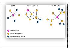
ZigBee support three types of network topologies: star topology, peer-to-peer topology and cluster-tree topology. The structures of these topologies are shown in Fig 5.
Fig 5: Network Topologies
By using peer-to-peer topology the system establishes Zigbee
Mesh Network.
In a peer-to-peer topology (also called mesh) there is, as in the star topology, always one PAN coordinator. The difference here is that any device can communicate directly with any other device within the range, not only with the PAN coordinator. A device can also communicate with a device located outside its range using multi-hop routing through contiguous devices. Peer- to-peer topologies are suitable for applications where self- configurability and large coverage are important.
B. BLUETOOTH
Bluetooth is a proprietary open wireless technology standard for exchanging data over short distances (using short-wavelength
along with the satellites' locations are used with the possible aid of trilateration (fig 6&7), depending on which algorithm is used, to compute the position of the receiver. This position is then displayed, perhaps with a moving map display or latitude and longitude; elevation information may be included. Many GPS units show derived information such as direction and speed, calculated from position changes.
Three satellites might seem enough to solve for position since space has three dimensions and a position near the Earth's surface can be assumed. However, even a very small clock error multiplied by the very large speed of light the speed at which satellite signals propagate — results in a large positional error.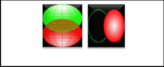
Position calculation introduction
Fig 6&7: Two sphere surfaces intersecting in a circle & Surface of sphere intersecting a circle (not a solid
disk) at two points
Using messages received from a minimum of four visible satellites, a GPS receiver is able to determine the times sent and then the satellite positions corresponding to these times sent. The
IJSER
radio transmissions in the ISM band from 2400–2480 MHz) from
fixed and mobile devices, creating personal area networks (PANs) with high levels of security. Created by telecoms vendor Ericsson in 1994, it was originally conceived as a wireless alternative to RS-232 data cables. It can connect several devices, overcoming problems of synchronization.
Implementation
Bluetooth uses a radio technology called frequency-hopping
spread spectrum, which chops up the data being sent and transmits chunks of it on up to 79 bands (1 MHz each; centered from 2402 to 2480 MHz) in the range 2,400–2,483.5 MHz (allowing for guard bands). This range is in the globally unlicensed Industrial, Scientific and Medical (ISM) 2.4 GHz short-range radio frequency band. It usually performs 800 hops per second, with AFH enabled.
C. GLOBAL POSITIONING SYSTEM (GPS)
The Global Positioning System (GPS) is a space-based satellite navigation system that provides location and time information in all weather, anywhere on or near the Earth, where there is a clear line of sight to four or more GPS satellites. It is maintained by the United States government and is freely accessible to anyone with a GPS receiver. The GPS program provides critical capabilities to military, civil and commercial users around the world. In addition, GPS is the backbone for modernizing the global air traffic system.
Basic Concept
GPS receiver calculates its position by accurately timing the
signals sent by GPS satellites high above the Earth. Each satellite continually transmits messages that include the time the message was transmitted satellite position at time of message transmission. The receiver uses the messages it receives to determine the transit time of each message and computes the distance to each satellite using the speed of light. These distances
x, y, and z components of position, and the time sent, are
designated as where the subscript i has the value 1, 2, 3, or 4. Knowing the indicated time the message was received ,the GPS receiver computes the transit time of the message as. A pseudo range, is computed as an approximation of the distance from satellite to GPS receiver. A satellite's position and pseudorange define a sphere, centered on the satellite, with radius equal to the pseudorange.
The position of the receiver is somewhere on the surface of this
sphere. Thus with four satellites, the indicated position of the GPS receiver is at or near the intersection of the surfaces of four spheres. In the ideal case of no errors, the GPS receiver would be at a precise intersection of the four surfaces. If the surfaces of two spheres intersect at more than one point, they intersect in a circle. The article trilateration shows this mathematically. A figure, Two Sphere Surfaces Intersecting in a Circle, is shown above. Two points where the surfaces of the spheres intersect are clearly shown in the figure. The distance between these two points is the diameter of the circle of intersection. The intersection of a third spherical surface with the first two will be its intersection with that circle; in most cases of practical interest, this means they intersect at two points. Another figure, Surface of Sphere Intersecting a Circle (not a solid disk) at Two Points, illustrates the intersection. The two intersections are marked with dots. Again, the articletrilateration clearly shows this mathematically.
For automobiles and other near-earth vehicles, the correct position of the GPS receiver is the intersection closest to the Earth's surface. For space vehicles, the intersection farthest from Earth may be the correct one. The correct position for the GPS receiver is also on the intersection with the surface of the sphere corresponding to the fourth satellite.
IJSER © 2013 http://www.ijser.org
International Journal of Scientific & Engineering Research, Volume 4, Issue 12, December-2013 1926
ISSN 2229-5518
In various fields there is a need to manage geometric, geographic, or spatial data, which means data related to space. The space of interest can be, for example, the two-dimensional abstraction of (parts of) the surface of the earth that is, geographic space, the most prominent example, a man-made space like the layout of a VLSI design, a volume containing a model of the human brain, or another 3d-space representing the arrangement of chains of protein molecules.
At least since the advent of relational database systems there have been attempts to manage such data in database systems. The capability to deal with large collections of relatively simple geometric objects, for example, a set of 100 000 polygons
Several terms have been used for database systems offering such support like pictorial, image, geometric, geographic, or spatial database system. The terms “pictorial” and “image” database system arise from the fact that the data to be managed are often initially captured in the form of digital raster images (e.g. remote sensing by satellites, or computer tomography in medical applications).
What is a spatial database system?
a. A spatial database system is a database system.
b. It offers spatial data types (SDTs) in its data model and
query language.
c. It supports spatial data types in its implementation,
providing at least spatial indexing and efficient algorithms
are ubiquitous in geography, for example, highways, rivers, public transport, or power supply lines.
Graphical Input and Output
Traditional database systems deal with alphanumeric data types whose values can easily be entered through a keybord and represented textually within a query result (e.g. a table). For a spatial database system, at least when it is to be used interactively, graphical presentation of SDT values in query results is essential, and entering SDT values to be used as “constants” in queries via a graphical input device is also important.
Besides graphical representation of SDT values, another distinctive characteristic of querying a spatial database is that the goal of querying is in general to obtain a “tailored” picture of the space represented in the database, which means that the information to be retrieved is often not the result of a single query but rather a combination of several queries. For example, for GIS applications, the user wants to see a map built by overlaying graphically the results of several queries.
Requirements for spatial querying have been analyzed following list is given:
3. Graphical combination (overlay) of several query results. It
should be possible to start a new picture, to add a layer, or to remove a layer from the current display.
4. Display of context. To interpret the result of a query, e.g. a
for spatial join
IJSEpoint describing Rthe location of a city, it is necessary to show
1) sounds trivial, but emphasizes the fact that spatial, or
geometric, information is in practice always connected with “non-spatial” (e.g. alphanumeric) data. Nobody cares about a special purpose system that is not able to handle all the standard data modeling and querying tasks. Hence a spatial database system is a full-fledged database system with additional capabilities for handling spatial data.
2) Spatial data types, e.g. POINT, LINE, REGION, provide a fundamental abstraction for modeling the structure of geometric entities in space as well as their relationships (l intersects r), properties (area(r) > 1000), and operations (intersection(l, r) – the part of l lying within r). Which types are used may, of course, depend on a class of applications to be supported (e.g. rectangles in VLSI design, surfaces and volumes in 3d). Without spatial data types a system does not offer adequate support in modeling.
3) A system must at least be able to retrieve from a large
collection of objects in some space those lying within a particular area without scanning the whole set. Therefore spatial indexing is mandatory. It should also support connecting objects from different classes through some spatial relationship in a better way than by filtering the Cartesian product we consider spatial DBMS to provide the underlying database technology for geographic information systems (GIS) and other applications. The two most important instances of spatially related collections of objects are partitions (of the plane) and networks
A partition can be viewed as a set of region objects that are required
to be disjoint. Partitions can be used to represent thematic maps.
A network can be viewed as a graph embedded into the plane,
consisting of a set of point objects, forming its nodes, and a set of line objects describing the geometry of the edges. Networks
some background, such as the boundary of a state containing it
a raster image of the area can also nicely serve as a background.
5. A facility for checking the content of a display. When a picture (a map) has been composed by several queries, one should be able to check which queries have built it.
6. Extended dialog. It should be possible to use pointing devices
to select objects within a picture or subareas (zooming in), e.g. by dragging a rectangle over the picture.
7. Varying graphical representations. It should be possible to assign different graphical representations (colors, patterns, intensity, symbols) to different object classes in a picture, or even to distinguish objects within one class (e.g. use different symbols to distinguish cities by population).
8. A legend should explain the assignment of graphical representations to object classes.
9. Label placement. It should be possible to select object
attributes to be used as labels within a graphical representation. Sophisticated (“nice”) label placement for a map is a difficult problem, however.
10. Scale selection. At least for GIS applications, selecting
subareas should be based on commonly used map scales. The scale determines not only the size of the graphical representation, but possibly also what kind of symbol is used or whether an object is shown at all (cartographic generalization).
11. Subarea for queries. It should be possible to restrict
attention to a particular area of the space for several queries.
These requirements can in general be fulfilled by offering textual commands in the query language or within the design of a graphical user interface (GUI).
IJSER © 2013 http://www.ijser.org
International Journal of Scientific & Engineering Research, Volume 4, Issue 12, December-2013 1927
ISSN 2229-5518
Path planning [5][6] is one of the most key elements for navigating with an EPAS. Path planning is the determination of a path that an EPAS must take in order to pass over each point in an environment and path is a plan of geometric locus of the points in a given space where the EPAS has to pass through Path planning “enables” mobile EPAS to see the obstacle and generate an optimal path so as to avoid them. The search for a path which a EPAS (with specified geometry) has to follow in a described environment, in order to reach a particular position and orientation, given an initial position and orientation.
Path planning as an optimization problem according to definition that, in a EPAS and a description of an environment, plan is needed between start and end point to create a path that should be free of collision and satisfies certain optimization criteria such as shortest path.
Path planning properties
Path planning has a few main properties according to type of
environment, algorithm and completeness. The properties are whether it is static or dynamic, local or global and complete or heuristic.
Static: path planning refers to environment which contains no moving objects or obstacles other than a navigating system.
Dynamic: path planning refers to environment which contains dynamic moving and changing object such as moving obstacle.
Local and Global: path planning depend on algorithm where
navigation strategy as Focussed D* but is algorithmically simpler. In particular, it moves the robot from its current vertex to a given goal vertex on a given graph as follows: It always moves the EPAS on a shortest path from its current vertex to the goal vertex, and replans the shortest path when the edge costs change.
Table –I Terrain with Random Obstacles
Search Algorithm | Planning time |
Breadth-First search | 302.3msec |
Forward A* | 10.5 msec |
Backward A* | 7.29msec |
Dynamic A*(D*) | 6.41msec |
Focussed D* | 4.28msec |
D* Lite | 2.82msec |
Table: Terrain with random Obstacles
The overall system architecture of proposed EPAS system is shown in fig 8. The EPAS system composed of two main subsystems.
1. The first subsystem is the user EPAS main system consists of vision camera mounted on the headgear and holds the mobile cart with hand at ground level. It gathers information about the
surroundings and also sends the requests from the user to the
IJSER
the information about the environment is a priori or not to the
algorithm. If the path planning is a global, information about the environment already known based of map, cells, grid or etc and if the path planning is a local, the system has no information about the environment and system has to sense the environment before decides to move for obstacle avoidance and generate trajectory planning toward target.
Path planning Algorithms
EPAS operate in domains that are only incompletely known;
when they have to move from given start coordinates to given goal coordinates in unknown terrain. In this case, they need to be able to re-plan rapidly as their knowledge of the terrain changes.
The EPAS constantly plans a shortest path from its current coordinates to the goal coordinates under the assumption that unknown terrain is traversable. It can utilize initial knowledge of the terrain in case it is available. If it observes obstacles as it follows this path, it enters them into its map and then repeats the procedure, until it eventually reaches the goal coordinates or all paths to them are untraversable. This navigation strategy is an example of sensor-based motion planning
The most popular solution to this problem is D*Lite since it combines the efficiency of heuristic and incremental searches, yet it is different from real-time heuristic search methods, still inds shortest paths. It achieves a large speedup over repeated A*,Dynamic A*(D*),Lifelong Planning A*and Foccussed D* searches by modifying previous search results locally(see Table I).
D* Lite Algorithm
D* Lite Algorithm [5][6], is an incremental version of the
heuristic search method A* and combines ideas from Lifelong
Planning A* and Focussed D*. It implements the same
system and user receives the commands from the server through the DSP based MPU.
2. The second subsystem is the EPAS server, processes the collected information from the ZigBee network and also the information received from the user, which are vision sensor information, sensors information and the GPS data i.e. spatial data to generate the output to direct the user to the requested target
The system will sense, evaluate and process the gathered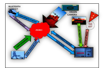
information from the user activities in order to provide proper guidance through commands. These guiding commands are based on user location at real time.
Fig 8: EPAS System Architecture
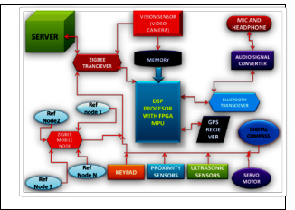
The Block diagram of the EPAS main system shown in fig 9. This system consists of FPGA based DSP Processor, vision sensor, ZigBee transceiver, Bluetooth headset and transceiver, GPS receiver, ZigBee network, proximity sensors, ultrasonic sensors, servomotor and Server.
IJSER © 2013 http://www.ijser.org
International Journal of Scientific & Engineering Research, Volume 4, Issue 12, December-2013 1928
ISSN 2229-5518
generate voice commands in words and users heard by means of headphones.
3. At the ground level a user can hold the mobile cane which incorporates the Keypad, ZigBee blind node, digital compass Proximity sensors, Ultrasonic sensors and Servomotor. The Sensors which are fixed in mobile cane, at
1200 degrees, with the proximity sensors and the Ultrasonic sensors alternatively. During operation, the user pushes the
mobile cane forward while traveling, and sensors detect obstacles in a 1200 wide sector ahead of the user through the ZigBee transceiver.
Fig 9: EPAS System Block Diagram
The mobile cane incorporates ZigBee blind node and corresponding reference nodes are fixed in each every room of the user and navigating areas like his/him house, office etc.
1. The ZigBee reference nodes shown in fig 10 are static and places in the known area are likely fixed in four sides of the wall in every room and in corridors, these nodes are fixed in two sides of the wall. It is a node that knows its own position and can tell other nodes on request its coordinates. A blind node is which collects signals from all reference nodes corresponding to a request and read the respective RSSI
4. This mobile cane can detect the obstacles in front of the Blind person at the ground level and measures the distance between obstacles and user using Proximity sensors.
5. When the obstacle is detected the mobile cane can change the path of the user by instructing the inbuilt servomotor to steer left or right using the obstacle avoidance [11][12] and the optimal path planning algorithms[5][6].
6. When the user wants to navigate, using the mobile cane, the Keypad which acts as a controlling element. It has four buttons (Left, Right, Top and Bottom). The Left Button acts as a left steer, right button acts as a right steer, top button acts as straight way and finally bottom one acts as a brake.
7. The information received from detected obstacles is
IJSER
values and feed the collective values to the hardware engine.
Afterwards it reads out the calculated position and sends the
information to the server via the control application This will form the ZigBee mesh network
Fig 10: ZigBee Blind Nodes and Reference Nodes
2. ZigBee blind node estimates the location [7][8][9[10] of the user with respect to predefined maps of the known closed environments. The users may generally stay and steer around his/her house and office areas. The potential destinations are stored and their locations are saved with respect to the virtual map of the system. The ZigBee mobile node uses the power estimation algorithm that is based on range measurements using received signal strength from fixed reference nodes. The orientation of the user is acquired from the Digital compass attached to the mobile cane in order to allow the system identify the direction on the map from the user current location to the target location. Concurrently, the ZigBee mobile nodes and Digital compass will detect the user position and orientation. The above two readings will be processed by the DSP processor in mobile cane and transmit them via ZigBee mesh network to the server. The ZigBee coordinator connected to the server and collects data and feed it to the EPAS system. The DSP processor receives information from the ZigBee interface and sends that to audio signal converter through Bluetooth to
processed by the DSP Processor and can be converted into sound signals and then stored in server through the ZigBee transceiver.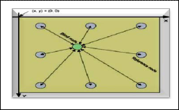
8. The user can wear the Vision sensor (video camera) on the head that capture the images in front of him/her. These images can be sent to the FPGA based DSP processing unit (MPU) through the Wireless Connection ZigBee transceiver.
9. Before sending the images to the MPU, the images have to be store in memory unit. Vision sensor continuously captures 24frames (video image) per second. These images are first stored in the memory unit and then sent to MPU for image processing.
10. The MPU processes the images with the image processing concepts such as preprocessing(resize of image into 256 x
256 pixels), Edge detection( using canny detection
algorithm), Edge linking(The two edge pixels are linked by the candidate edge pixel thus forming an edge link), Object enhancement(Flood Fill operation), noise elimination(Morphological operations, erosion and dilation are employed to eliminate noise in the image)., disparity calculation(Area based stereo matching is performed over the stereo image pair) and object preference(the object, the central of image pixel area is called as iris area this will calculated using Fuzzy logic). The designed fuzzy system produces three outputs, which are low, medium and high preferences.
11. With these image processing concepts, the background objects of the image can be suppressed and foreground objects are considered. The foreground and background objects have different frequencies such as low and high respectively. The image with pixels of high intensity will
IJSER © 2013 http://www.ijser.org
International Journal of Scientific & Engineering Research, Volume 4, Issue 12, December-2013 1929
ISSN 2229-5518
produce sound of higher amplitude. On the other hand, image with pixels of low intensity will produce sound of lower amplitude. The foreground objects with low frequency indicate objects that are closed to the Blind person. Due to the above reason, the close object image can be converted into sound signals. These signals are stored in server.
12. The image sound signals and obstacle sound signals, which
are stored in server, are converted as audio signals in the audio converter and sent to the Bluetooth Headphones.
13. The Global Positioning System (GPS) gives the information about the location and positions of in an open environment. In an open environment the user can navigate through in any location. The user navigating locations can be updating time to time in the server. The ZigBee mesh network only gives the information about location and position of the closed environment, because the GPS doesn’t work in closed environments. According to this application for closed environment we use ZigBee localization [7][8][9[10] technique by using ZigBee mesh network. This information is stored in the server through the MPU.
14. Once the user sends a request for a desired destination or object, the server will identify the location of that object.
15. The server will use a routing algorithm[5][6] to create a path between the user and the desired object in a virtual map.
16. Using the generated path, the server will prepare a set of
voice commands to direct user to the requested target.
4. When the user is near an obstacle, the proximity sensor, ultrasonic sensor and server give obstacle detection algorithm will generate a caution command through the Bluetooth headphones that increase according to the distance between the user and the obstacle.
5. ZigBee Transceiver receives other signals like Keypad and Servomotor signals processed in the MPU sent for storage in server this gives the user orientation. The user orientation is calculated by using the path planning algorithm. Here the best path planning is implemented is D* lite algorithm [5][6].
6. ZigBee Transceiver receives input from the vision sensor (video camera), image processed signals are sent to the Server for the storage of sound converted signals. In front images are converting to sound signals; these sound signals are stored in the server, and then converted to audio signals like, verbal commands by using audio converter which is connected to our system.
7. The GPS receiver collects data from spatial databases. It gives the information of the position and location of the user. The server can collect spatial data from the Google maps of the user locations, which is connected to the internet and have a navigator application in server. The user will navigate from one location to another location, time to time in open environments. Each and every spatial data (Location Map) is stored every time in server. Each time D*lite
algorithm [5][6] calculates the path planning. If the user
IJSErequest is the oRld requistation then no need to calculate path
Fig 11 shows Server System block consists of Several Blocks
Fig 11: EPAS System Server
1. The server receives data from the zigbee reference nodes
arranged in a mesh network mounted at the fixed closed locations like four side walls of the room and two sides of the corridor in offices and houses. The server receives user locations to update his location with respect to predefined virtual map of closed environment.
2. The possible destinations will be stored in the server and their locations are saved with respect to predefined virtual map of the closed environment.
3. Using the generated path, the server will prepare a set of voice commands to direct user to the requested target. The server will send voice commands, while in the mean time it will update the position of the user based on the received data from him.
again. The stored and calculated spatial data in the server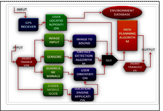
must be faster than path planning [5][6] calculation of the new one.
8. D* Lite algorithm[5][6], that repeatedly determines shortest paths between the current vertex of the EPAS and the goal vertex as the edge costs of a graph change while the EPAS moves towards the goal vertex. D* Lite[5][6] does not make any assumptions about how the edge costs change, whether they go up or down, whether they change close to the current vertex of the robot or far away from it, or whether they change in the world or only because the knowledge of the EPAS changes. The goal-directed navigation problem in unknown terrain then is a special case of this problem. This algorithm is developing to provide this capability, but in real-time. This is a planning algorithm that produces an initial plan based on known and assumed information, and then incrementally repairs the plan as new information is discovered about the world.
All the above information are monitor in the Personal Computer (PC) or Laptop with a GUI software and the server also gives the Optimal Path Planning [5][6] to the EPAS system through the ZigBee Transceiver.
5. Hardware
The set of major components that have been utilized to develop such system are:
a. Vision Sensor: Vision sensor, which is used for this system
digital camera.
b. Micro Processing Unit: This is the main unit for the entire
Blind Assistance Electronic Travel Aid. For this application, we use the FPGA based DSP processors because it processes the image and audio signals.
IJSER © 2013 http://www.ijser.org
International Journal of Scientific & Engineering Research, Volume 4, Issue 12, December-2013 1930
ISSN 2229-5518
c. Analog Converter: In signal processing, an audio converter or digital audio converter is a type of electronic hardware technology which converts an analog audio signal to a digital audio format, either on the input (Analog-to-digital converter or ADC), or the output (Digital-to-analog converter, or DAC).
d. Zigbee Transceiver: The CC2520 is TI's second generation
Zigbee/ IEEE 802.15.4 RF transceiver for the 2.4 GHz unlicensed ISM band. This chip enables industrial grade applications by offering state-of-the-art selectivity/co- existence, excellent link budget, operation up to 125°C and low voltage operation. In addition, the CC2520 provides extensive hardware support for frame handling, data buffering, burst transmissions, data encryption, data authentication, clear channel assessment, link quality indication and frame timing information. These features reduce the load on the host controller.
e. Bluetooth Transmitter & Receiver: It is used to connect the headphones and mike.
f. Proximity Sensors: A proximity sensor is a sensor able to detect the presence of nearby objects without any physical contact. A proximity sensor often emits an electromagnetic field or a beam of electromagnetic radiation (infrared, for instance), and looks for changes in the field or return signal. The object being sensed is often referred to as the proximity sensor's target. Different proximity
sensor targets demand different sensors.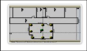
desired target. This algorithm is simply connecting between two points, which are the user, and the desired target. However, for enhancement the system has the ability to adapt any complex path planning algorithm
Fig 12. Application Software GUI
This paper presented for the design of a system that assists the blind to navigate inside a closed environment such as the home and outdoor environment with something like visual perception. The system can be considered as a semi-autonomous device. It provides full autonomy for global navigation (path-planning & localization [8]), but relies on the skills of the user for local
IJSnEavigation (ObstaRcle avoidance [6][7]). This device offers
g. Ultrasonic Sensors: Ultrasonic sensors (also known
as transceivers when they both send and receive) work on a principle similar to radar or sonar which evaluate attributes of a target by interpreting the echoes from radio or sound waves respectively. Ultrasonic sensors generate high frequency sound waves and evaluate the echo which is received back by the sensor. Sensors calculate the time interval between sending the signal and receiving the echo to determine the distance to an object.
h. A servomotor is a motor which forms part of a servomechanism. The servomotor is paired with some type of encoder to provide position/speed feedback. This feedback loop is used to provide precise control of the mechanical degree of freedom driven by the motor. A servomechanism may or may not use a servomotor. For example, a household furnace controlled by a thermostat is a servomechanism, because of the feedback and resulting error signal, yet there is no motor being controlled directly by the servomechanism. Servomotors have a range of 0°-180°.Servomotors are not the only means of providing precise control of motor output. A common alternative is a stepper motor. In a stepper motor, the input command specifies the desired angle of rotation, and the controller provides the corresponding sequence of commutations without the use of any feedback about the position of the system being driven.
6. Software
An interface is designed to enable the system administrator to debug the system, or monitor the movement of the blind person for the environment (fig 12). The user icon in the interface continuously follows the location of the blind node, which makes the guidance procedures more accurate. Finally, the software also handles the path-planning algorithm, where Re-active path planning method is used to connect between the user and the
pioneering solutions in order to replace the straight methods of guiding visually impaired person. In addition, it can be easily applied anywhere where it can handle places like malls, Railway stations, bus stand, universities and airports. This system will allow the visually impaired to wander freely and autonomously
![]()
[1]Akella.S.Narasimha Raju et al,”Navigating By Means Of Electronic Perceptible Assistance System”, International Journal of Engineering Research & Technology (IJERT), ISSN: 2278-0181,Vol. 1 Issue 5, July –
2012
[2].Wearable Obstacle Avoidance Electronic Travel Aids for Blind: A Survey
Dimitrios Dakopoulos and Nikolaos G. Bourbakis, Fellow, IEEE TRANSACTIONS ON SYSTEMS, MAN, AND CYBERNETICS—PART C: APPLICATIONS AND REVIEWS, IEEE, VOL. 40, NO. 1, JANUARY
2010
[3].G. Sainarayanan, R. Nagarajan, and S. Yaacob, “Fuzzy image processing scheme for autonomous navigation of human blind,” Appl. Softw.Comput.,
vol. 7, no. 1, pp. 257–264, Jan. 2007.
[4]. IA: Syst. Hum., vol. 31, no. 2, pp. 131–136, Mar. 2001.. Ulrich and J. Borenstein, “The guidecane – applying mobile robot technologies to assist the
visually impaired people,” IEEE Trans. Syst.,Man Cybern., A: A: Syst. Hum., vol. 31, no. 2, pp. 131–136, Mar. 2001.yst. Hum., vol. 31, no. 2, pp. 131–136, Mar. 2001.
[5].Fast Replanning for Navigation in Unknown Terrain Sven Koenig, Member, IEEE, Maxim Likhachev, IEEE TRANSACTIONS ON ROBOTICS AND AUTOMATION, VOL. XX, NO. Y, MONTH 2002
[6]. Incremental Replanning for Mapping Maxim Likhachev, Sven Koenig [7].Position Location Monitoring Using IEEE® 802.15.4/ZigBee® technology Oziel Hernandez, Varun Jain, Suhas Chakravarty and Prashant Bhargava
[8]. An Indoor Localization System using RSSI Measurement of a Wireless
Sensor Network based on the ZigBee Standard Masashi Sugano,Tomonori
Kawazoe, Yoshikazu Ohta , and Masayuki Murata
[9]. A RSSI-based Algorithm for Indoor Localization Using ZigBee in
Wireless Sensor Network Yu-Tso Chen, Chi-Lu Yang, Yeim-Kuan Chang,
Chih-Ping Chu
IJSER © 2013 http://www.ijser.org
International Journal of Scientific & Engineering Research, Volume 4, Issue 12, December-2013 1931
ISSN 2229-5518
[10]. Indoor Room Location Estimation Kevin D’HOE, Geoffrey OTTOY, Philip KEERSEBILCK, Jean-Pierre GOEMAERE, Lieven De STRYCKER.
9th International Conference on DEVELOPMENT AND APPLICATION SYSTEMS, Suceava, Romania, May 22-24, 2008
[11] I. Ulrich and J. Borenstein, “VFH+: Reliable obstacle avoidance for fast
mobile robots,” in IEEE Int. Conf. Robotics and Automation, Leuven, Belgium, May 1998, pp. 1572–1577.
[12] “VFH*: Local obstacle avoidance with look-ahead verification,” in IEEE
Int. Conf. Robotics and Automation, San Francisco, CA, Apr.2000, pp. 2505–
2511.
PROFILES

Akella.S.NarasimhaRaju, M.Sc;MPhil;MTech., Assistant Professor in Computer Science & Engineering at V.S.M College of Engineering, Ramachandrapuram, E.G.Dt, AP, India. He has 11 years of teaching experience. His areas of interest include Embedded Systems, Communication
Systems and Wireless Communication and Image Processing.
Email: akella.raju@gmail.com
S N Ali Ansari, MTech., Associate Professor in Computer Science &Engineering at V.S.M College of Engineering, Ramachandrapuram, E.G.Dt,AP,India. He is Pursuing Doctor of Philosophy. He has 18 years of teaching experience. His areas of interest include Data
Mining, Spatial Databases, and Artificial Intelligence. Email: ansarisn@gmail.com
Ch.Karunakar, MTech. Assistant Professor in Computer Science & Engineering at V.S.M College of Engineering, Ramachandrapuram, E.G.Dt. He has 4 and half years of teaching experience His areas of interest includes Computer networks and Network security and Wireless communication Networks.
Email: karunakar.chappidi@gmail.com
IJSER © 2013 http://www.ijser.org