International Journal of Scientific & Engineering Research Volume 3, Issue 7, June-2012 1
ISSN 2229-5518
Nwankwojike, B. Nduka
Abstract
Network analysis technique was used in this study to establish the optimal duration and labour cost of overhauling ABB type 13D gas turbine in Nigeria as well as the critical jobs that required adequate management attention/supervision in order to check corrupt upward review of project cost that characterized this sector resulting from intentional delays in the execution of turbine overhauling projects in this country. Results showed one thousand, two hundred and forty- three (1243) hours or approximately 155.38 days (at 8 working hours per day) and four million, twelve thousand and five hundred naira (N4,012,500.00) as the respective optimal duration and labour cost of the project. In addition, activities A, B, D, G, H, J, L, N, O, P, R, S, U and V were revealed as the critical jobs of this maintenance project while the optimal specific number of various types of manpower required to achieve these optimal duration and cost were determined as ten engineers, twenty technologists, seven craftmen and forty- five unskilled labourers.
Key Words: Critical jobs, electricity generation, gas turbine, network analysis, optimal cost, optimal duration, overhauling maintenance,
Electricity is one of the most basic necessities for a healthy and viable national economy because of its important as raw material in modern industry/commerce and for raising the quality of life [1], [2]. Thus, the desire for electricity is so high that today, one easily finds individual self generating electric power plants in almost all resident homes and business outfits of Nigeria due to inability of Power Holding Company of Nigeria (PHCN), the statutory body responsible for electricity generation and distribution to meet the demand. The problems of this small scale self electricity generation such as limited capacity, high energy and exergic losses, high cost of production, hazardous gases and noise emissions have been acknowledged [1], [3], [4], [5]. Although, these authors collectively emphasized 24-hour uninterruptible public electricity service of satisfactory quality as the sure measure to avert these problems associated with rampant use individual electric generators in this country, [2], said that this is not likely to be met in the near future. This is because of long neglect of power sector by government and inadequate electric power generating capacity of PHCN. Based on the internationally advocated minimum electricity consumption of 6.5MWH per head per year as obtainable in the developed countries and Nigeria population of 150 million people, the estimated electricity requirement of the country is over
108.6GW, thus, the installed electric power capacity (6.6GW)
of PHCN which only a percentage is actually being produced is grossly inadequate. Therefore, one of the major challenges of the government and people of Nigeria today is how to bring up this very low level of large scale electricity generation to match the nations requirement.
Electricity generation is basically conversion of other
energy forms into electrical energy. According to [2], electrical
generator is the only practical device currently available in Nigeria for the large scale conversion of energy from other sources into electricity and this is a rotational device. Thus, other energies are normally converted into intermediate turning energy (mechanical torque) using turbines before final transformation into electrical form as the turbine drives the generator. A turbine can be hydraulic (water) or steam/gas driven, of which the latter type is far more common and constitutes over 70% of the total Nigerian’s electricity supply. It is therefore very obvious that the reliability of this nation’s electricity sector depends partly on the effective installation, operation and maintenance of turbines in our various power stations. This view is in line with the assertion that grossly inadequate functional generating units especially the turbines in our national power stations constitute the major cause of unreliable electric power sector in this country [2]. It is as a result of this that Federal Government Nigerian came out with policies/programmes on massive rehabilitation/refurbishment of all dilapidated units/equipment especially the turbines in the existing power stations and establishment of more power stations in 1999 through her Power Reform Programme/National Integrated Power Projects (NIPPs) in order to bring the nations electric power generation capacity to match consumption.
However, despite all these articulated policies/efforts the achievement of uninterruptible public electricity service of satisfactory quality may not be possible in this country in the near future as predicted by [2], because the planned rehabilitation of the dilapidated turbines is yet to start in
IJSER © 2012
International Journal of Scientific & Engineering Research Volume 3, Issue 7, June-2012 2
ISSN 2229-5518
many stations ten years after the commencement of the reform even though most of new stations have either been completed
or at advance stage of completion. In addition, most of the turbine overhauling projects started in the past are presently abandoned due to insufficient fund budgeted for their execution caused by inadequate fair data on their possible duration during initial planning. Unnecessary delay during execution of some of the rehabilitation projects by some corrupt government officials in collaboration with some expatriates to pave way for cost review on the account of upward deviation of materials and other engineering services costs over the project period is one of the major causes of this financial crisis. On the other hands, unnecessary rushing during the execution of some completed turbine rehabilitation projects especially when commissioning date approaches caused some costly mistakes which shouldn’t have been, if those projects were allowed to take normal/optimal durations, thus, a good number of the so rehabilitated plants remained unproductive. Although, non-manufacture of major electrical generating units/equipment in this country and the use of expatriates for major maintenance works in this sector as well as instability of our currency contribute substantially to this costing problem, establishment of an empirical model/data on the optimal duration and labour cost required for overhauling turbines in our national electric power generating stations will check these corrupt activities. The savings from the application of the optimal turbine overhaul duration and labour cost model/data will be used for quick resurrection of the existing power plants and also to ensure that the newly established and future ones will not suffer the same faith.
In most industrial/scientific project evaluation and control, techniques such as simple bar chart, milestone chart,
Gant chart, line of balance and network analysis are used quite extensively [6]. However, most modern project scheduling, planning, monitoring, co-ordination and control problems lend themselves to network modeling (network analysis) because it is an outstanding tool for predicting all activities required for successful projects completion with minimum resources and time [7], [8]. Network Analysis is a generic name of two major practices, critical path method (CPM) and programme evaluation and review technique (PERT). CPM is deterministic and does not account for uncertainties involved in a job (or activity) time estimate while PERT, as a probabilistic model takes care of this shortcoming of CPM, hence, both are usually applied as twins to improve efficiency of project execution within predetermined time and cost [8], [9]. Application of these techniques is most appropriate for planning and execution of large time/fund-bound projects which involve careful coordination of complex and interrelated activities and resources such as assembly works, installation, maintenance and phasing out of facilities/plants,
research and developments, logistic management, marketing, construction of building, estates, factories, roads, ships,
airplanes and water scheme [6], [7], [10]. According to [8] and [9], the technique reveals the earliest and latest start and finish dates of each activity in any project, activity floats, slacks and optimal duration and cost of the project as well its critical phases that required close monitoring.
Earliest start and finish date are earliest possible date an individual activity in a project can start and finish respectively while the latest start and finish dates constitutes the latest possible start and finish dates for a job without jeopardizing with the timely completion of project. Slack is the amount of freedom or latitude available in deciding when to start an activity without jeopardizing with the optimal project duration [7]. Cheema [8], classified activity float as free, independence, Interference and total floats; free float is the amount of spare time available to any activity provided that any delay in it does not delay the completion of any subsequent activity; independence float is the amount of time a job can be delayed without affecting the entire project duration if all preceding activities are completed as late as possible and all succeeding activities are completed as early as possible. Total float is the maximum amount of spare time available to any activity without minding if any delay in the activity affects the timing of other activities provided that the overall project time is not extended while interference float constitutes the difference between total float (TF) and free float (FF) of that activity. If all these floats and slack of each activity lying on a network path are zero, the path is confirmed as “Critical Path”, thus, all activities in this path are critical jobs while the total duration of all the critical jobs constitutes the possible project duration [6], [7], [8], [9]. It is obvious from these descriptions that prediction of these parameters at the initial planning, budgeting and awarding of contract for turbine overhauling projects in this nation will check the excesses of our corrupt officials and expatriates. Prediction of these parameters with respect to turbine overhauling in this country is also of economic sense to know the exact time the expatriates is required in order to reduce logistic costs such as exorbitant hotel bill/daily allowance among others associated with hosting of foreign personnels. The saving resulting from this prediction will make more funds available for this aspect of power reform programme (rehabilitation of the existing power stations) and other developmental projects. It is therefore the objective of this work to use network analysis technique to determine the optimal duration and labour cost of overhauling a gas turbine at Afam power station to serve as a model/guide for planning and budgeting of such project in other electric power generating stations.
IJSER © 2012
International Journal of Scientific & Engineering Research Volume 3, Issue 7, June-2012 3
ISSN 2229-5518
This study involved direct practical participation in the overhauling of three ABB Type 13D gas turbines (GT 13, GT 17
and GT 18) with installed capacity of 75MW each at Afam power station in River State of Nigeria, during which distinct jobs of the project were identified with the man hours (duration) and labour cost involved per activity using work break-down structure (WBS) and cost break-down structure (CBS) procedures. ABB Type 13D turbine machine is a simple design open cycle gas turbine comprising mainly of lube oil, cooling water and air intake systems, compressors, turbine stator and rotor as well as natural gas supply system comprising of both the gas scrubbers and control valves. The
where t0 = optimistic duration; tm = most likely duration;
tp = pessimistic duration.
Thereafter, the determined precedence order and expected durations of the activities involved in overhauling of the turbines were used to draw a logical sequence network diagram of the projects.
The arithmetic analysis of the network which involve
determination of the Earliest Start dates (ES), Earliest Finish dates (EF), Latest Start dates (LS), Latest Finish dates (LF), Slack (SL) and floats [free (FF), independence (IF), interference (INF) and total (TF)] for each activity were performed using the following models [6], [7], [8], [9];
lube oil system circulates oil for lubrication, cooling, jacking and control purposes while the cooling water system circulates the water meant for cooling the generator stator windings. The turbine rotor is mounted with that of generator on four journal bearings with each positioned at both ends of the generator. The turbine end of this unit is open to the exhaust stack through an exhaust diffuser. Both the compressor and turbine casings were build in halves for easy access to the blades during maintenance. On the upper half of the turbine casing was mounted the combustion chamber
internally lined with ceramic tiles which serves as heat shields.
EF ES te LS LF te LF ES te SL LF EF
FF ES j ES i te
IF EF LS te
INF LF EF FF
TF LF ES te
(3) (4) (5) (6)
(7)
(8) (9) (10)
At the upper end of the combustion chamber is a flange with
Where
ES j
and
ES i
constitute the earliest start dates of
provisions for gas passage and gas burner mountings.
The overhaul maintenance of this electricity generation
gas turbine comprises of several activities which fall under
three major variant phases, dismantling/inspection of the unit’s components for repair or replacement, repair/replacement/reassembling and testing/commissioning of the unit. The precedence order of various activities involve in this overhauling projects was established by identifying activities that must be completed before starting a particular activity (predecessor activities), activities that must follow a particular activity (successor activities) and activities that can be performed simultaneously. The duration of each activity was measured using stop watch during the three turbines overhaul. The activity duration data obtained from these three experimental measurements were also used together with fair records of other turbines overhauled in the past to establish multiple (three) time estimates of each of the optimistic, most likely and pessimistic durations of all the activities. The mean values of these three time variables per activity were later computed and used to determine the expected duration (time),
successor and concerned activities respectively. Earliest start dates were determined by working forward through the network, adding up activities durations successively, where there were more than one possible figure the highest one was used. Contrary, the latest finish dates were obtained by working from the end of the network, subtracting the activities durations successively where there were more than one possible figure the lowest one was taken. Activities with zero slack and floats were identified from the arithmetic analysis in accordance with [8], as critical activities that required close supervision in the turbine overhauling maintenance while the path within which the critical activities fall in the network is the critical path. Thereafter, the total duration of the critical activities/path which is the minimum possible duration of the turbine overhaul project was computed in accordance with [6], [7], [8] and [9]. The labour cost per activity was determined based on contract terms and prevailing economic condition in River State of Nigeria as well as the man hour of various categories of personnels (both local and expatriates) involved in carrying out the activities where
te, of each activity as well as the estimates variance, e
following relations given by [7], [8], [9] as;
t0 4t m t p
using
N780, N560, N440 and N330 constituted respective average
basic wage per hour paid to engineers, technologists, craftsmen/artisans (welder, crane operator, and electrician)![]()
te
6
![]()
t p t0
e 6
(1) (2)
and unskilled labourer in the three projects studied.
IJSER © 2012
International Journal of Scientific & Engineering Research Volume 3, Issue 7, June-2012 4
ISSN 2229-5518
The work breakdown structure indicating the precedence order of various activities involved the ABB type 13D gas
turbine overhauling at Afam power station and the analysis of their measured multiple time estimates are presented in Tables 1 and 2 respectively while Fig. 1 showed the network diagram of the project. The arithmetic analysis of this project network shown in Table 3 and Fig. 2 revealed A, B, D, G, H, J, L, N, O, P, R, S, U and V as critical jobs in this overhauling project and a total one thousand, two hundred and forty- three (1243) hours or approximately 155.38 days (at 8 working hours per day) as the minimum possible duration of this project.
Table 4 shows the number of various categories of workers as well as the cost implication of each job in the project. The
optimal specific number of various types of manpower required for this overhauling project was determined as ten (10) engineers, twenty (20) technologists, seven (7) craftmen and forty- five (45) unskilled labourers using results/data contained in this table (Table 4) and the precedence order of the project activities/network. Also, this table (Table 4) revealed four million, twelve thousand and five hundred naira (N4,012,500.00) as the optimal cost of labour required in this maintenance project.
TABLE 1
![]()
![]()
WORK BREAKDOWN STRUCTURE OF ABB TYPE 13D GAS TURBINE OVERHAULING PROJECT
Activity | Description | Predecessor Activities | |
A | Dismantling/Isolation of various components of the turbine unit. | - | |
B | Dismantling and inspection of compressor and exhaust end journal bearing, combustion chamber, blow-off value silencer and air duct. | A | |
C | Dismantling and inspection/servicing of intermediate shaft and gear box components. | A | |
D | Dismantling and inspection/servicing of compressor inlet manifold and thermal block. | B | |
E | Generator rotor extraction. | C | |
F | Inspection and servicing/repair of generator components | E | |
G | Dismantling/Inspection of upper halves of GT internals. | D | |
H | Lifting of GT rotor and lower halves of GT internals. | E, G | |
I | Inspection and servicing of auxiliary units of the turbine; | A | |
J | Deblading and repair of GT rotor and stator blade carrier. | H | |
K | Inspection and repair of auxiliary GT components. | H | |
L | Blading of GT rotor and stator blades. | J | |
M | Draining and refilling of the oil reservoir. | I | |
N | Ordering and receiving of components for replacement as well as arrangement of all repaired components and spares of components to be replaced and mechanical fasteners according to assembly procedure. | K, L | |
O | Installation of GT internals (lower halves) | N | |
P | Installation of GT rotor and intermediate shaft, lead printing, bearing and Labyrinth seal clearance checks, and taking coupling run-out. | O, M | |
Q | Installation of generator rotor and pressure testing of the generator cooling water supply system. | F, P | |
R | Installation of upper halves of the GT internals and thermal block. | P | |
S | Installation of air intake system, blow-off valve silencer and combustion chamber. | R | |
T | Re-alignment of the generator rotor to the turbine rotor and mounting of gear box. | Q | |
U | Installation of instrumentation/control devices and simulation of the GT control systems. | S, T | |
V | Testing of the unit/commissioning. | U |
IJSER © 2012
International Journal of Scientific & Engineering Research Volume 3, Issue 7, June-2012 5
ISSN 2229-5518
TABLE 2
ANALYSIS OF MULTIPLE TIME ESTIMATES OF ABB TYPE 13D GAS TURBINE OVERHAULING PROJECT
Activity | Duration (Hour) | |||||||||||||
Optimistic | Most Likely | Pessimistic | te | e | ||||||||||
t 01 | t02 | t 03 | t 0 AV | t m1 | t m 2 | t m 3 | t mAV | t p1 | t p 2 | t p 3 | t pAV | |||
A | 48 | 50 | 52 | 50 | 56 | 55 | 57 | 56 | 62 | 63 | 61 | 62 | 56 | 2.33 |
B | 107 | 105 | 107 | 106 | 128 | 127 | 129 | 128 | 144 | 144 | 144 | 144 | 127 | 6.67 |
C | 40 | 41 | 39 | 40 | 48 | 49 | 47 | 48 | 63 | 65 | 61 | 63 | 49 | 4.00 |
D | 88 | 89 | 84 | 87 | 104 | 104 | 104 | 104 | 128 | 127 | 126 | 127 | 105 | 6.83 |
E | 71 | 72 | 73 | 72 | 89 | 88 | 87 | 88 | 104 | 105 | 103 | 104 | 88 | 5.33 |
F | 56 | 57 | 55 | 56 | 72 | 71 | 73 | 72 | 88 | 89 | 87 | 88 | 72 | 5.33 |
G | 27 | 24 | 27 | 26 | 32 | 31 | 33 | 32 | 32 | 31 | 33 | 32 | 31 | 1.33 |
H | 32 | 33 | 31 | 32 | 40 | 41 | 40 | 40 | 42 | 44 | 40 | 42 | 39 | 1.33 |
I | 56 | 56 | 56 | 56 | 64 | 63 | 65 | 64 | 66 | 69 | 69 | 68 | 63 | 1.33 |
J | 24 | 24 | 24 | 24 | 32 | 31 | 32 | 32 | 32 | 35 | 35 | 34 | 31 | 1.33 |
K | 104 | 103 | 102 | 103 | 128 | 129 | 127 | 128 | 130 | 128 | 129 | 129 | 124 | 3.83 |
L | 175 | 179 | 177 | 177 | 200 | 200 | 200 | 200 | 199 | 198 | 200 | 199 | 196 | 3.83 |
M | 42 | 40 | 41 | 41 | 49 | 48 | 47 | 48 | 49 | 48 | 50 | 49 | 47 | 1.50 |
N | 56 | 55 | 57 | 56 | 72 | 71 | 71.5 | 71.5 | 72 | 71 | 73 | 72 | 69 | 2.67 |
O | 48 | 49 | 47 | 48 | 55 | 55 | 55 | 55 | 56 | 56 | 56 | 56 | 56 | 2.00 |
P | 61 | 65 | 66 | 64 | 67 | 67 | 68 | 67 | 80 | 85 | 83 | 82 | 69 | 5.33 |
Q | 80 | 81 | 79 | 80 | 95 | 96 | 94 | 95 | 104 | 104 | 104 | 104 | 94 | 4.00 |
R | 96 | 95 | 97 | 96 | 104 | 103 | 105 | 104 | 111 | 113 | 112 | 112 | 104 | 2.67 |
S | 128 | 127 | 129 | 128 | 144 | 146 | 145 | 145 | 168 | 169 | 167 | 168 | 146 | 6.67 |
T | 31 | 32 | 33 | 32 | 41 | 40 | 42 | 41 | 56 | 57 | 55 | 56 | 42 | 4.00 |
U | 71 | 72 | 72 | 72 | 96 | 96 | 96 | 96 | 120 | 120 | 120 | 120 | 96 | 8.00 |
V | 96 | 95 | 97 | 96 | 120 | 120 | 120 | 120 | 144 | 143 | 145 | 144 | 120 | 8.00 |
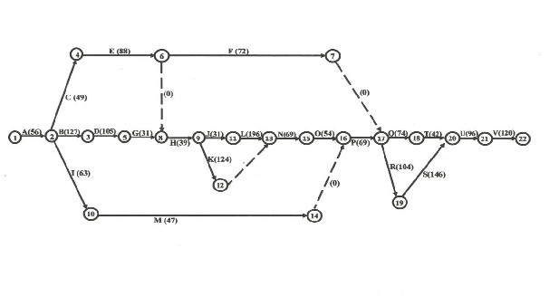
Fig. 1: Network diagram of ABB type 13D gas turbine overhauling project
IJSER © 2012
International Journal of Scientific & Engineering Research Volume 3, Issue 7, June-2012 6
ISSN 2229-5518
TABLE 3
ARITHMETIC ANALYSIS OF ABB TYPE 13D GAS TURBINE OVERHAULING PROJECT NETWORK
![]()
(Critical
![]()
![]()
Activity)
A (1-2) 56 0 56 0 56 0 0 0 0 0 Critical B (2-3) 127 56 183 56 183 0 0 0 0 0 Critical C (2-4) 49 56 105 56 231 126 0 0 126 126
D (3-5) 105 183 288 183 288 0 0 0 0 0 Critical
E (4-6) 88 105 193 231 319 126 0 -126 0 126
F (6-7) 72 193 265 319 777 512 0 -126 0 512
G (5-8) 31 288 319 288 319 0 0 0 0 0 Critical H (8-9) 39 319 358 319 358 0 0 0 0 0 Critical I (2-10) 63 56 119 56 661 542 0 0 542 542
J (9-11) 31 358 389 358 389 0 0 0 0 0 Critical
K (9-12) 124 358 482 358 585 103 0 0 0 103
L (11-13) 196 389 585 389 585 0 0 0 0 0 Critical
M (10-4) 47 119 166 661 708 542 0 0 542 542
N (13-15) 69 585 654 585 654 0 0 0 0 0 Critical
O (15-16) 54 654 708 654 708 0 0 0 0 0 Critical P (16-17) 69 708 777 708 777 0 0 0 0 0 Critical Q (17-18) 94 777 871 777 985 114 0 0 0 114
R (17-19) 104 777 881 777 881 0 0 0 0 0 Critical
S (19-20) 146 881 1027 881 1027 0 0 0 0 0 Critical
T (18-20) 42 871 913 985 1027 114 114 0 114 114
U (20-21) 96 1027 1123 1027 1123 0 0 0 0 0 Critical
V (21-22) 120 1123 1243 1123 1243 0 0 0 0 0 Critical
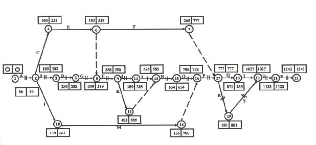
Fig. 2: Complete analyzed network diagram of ABB type 13D gas turbine overhauling project
IJSER © 2012
International Journal of Scientific & Engineering Research Volume 3, Issue 7, June-2012 7
ISSN 2229-5518
TABLE 4
ANALYSIS OF MANPOWER REQUIREMENTS/COST BREAKDOWN OF THE TURBINE OVERHAULING PROJECT
Activity | Man power Requirement | Duration (Hour) | Amount N K |
A | 4 engineers, 8 technologists and 8 unskilled labourers | 56 | 93,520.00 |
B | 4 engineers, 8 technologists, 4 craftmen and 15unskilled labourers | 127 | 323,850.00 |
C | 1 engineers, 2 technologists and 4 unskilled labourers | 49 | 81,830.00 |
D | 4 engineers, 8 technologists, 4craftmen and 15 unskilled labourers | 105 | 267,750.00 |
E | 2 engineers, 4 technologists and 10 unskilled labourers | 88 | 146,960.00 |
F | 2 engineers, 4 technologists and 4 unskilled labourers | 72 | 120,240.00 |
G | 2 engineers, 4 technologists, 2craftmen and 10 unskilled labourers | 31 | 79,050.00 |
H | 4 engineers, 8 technologists, 4 craftmen and 15 unskilled labourers | 39 | 99,450.00 |
I | 2 engineers, 4 technologists, 1craftman and 10 unskilled labourers | 63 | 132,930.00 |
J | 2 engineers, 4 technologists, 2 craftmen and 10 unskilled labourers | 31 | 79,050.00 |
K | 4 engineers, 8 technologists, 4 craftmen and 15 unskilled labourers | 124 | 316,200.00 |
L | 2 engineers, 4 technologists, 2 craftmen and 10 unskilled labourers | 196 | 499,800.00 |
M | 1 engineers, 2 technologists, 1craftman and 4 unskilled labourers | 47 | 99,170.00 |
N | 1 engineers, 2 technologists, 1craftman and 10 unskilled labourers | 69 | 145,590.00 |
O | 4 engineers, 8 technologists, 4 craftmen 15 unskilled labourers | 54 | 137,700.00 |
P | 4 engineers, 8 technologists, 2 Craftmen and 15 unskilled labourers | 69 | 145,590.00 |
Q | 3 engineers, 6 technologists and 10 unskilled labourers | 94 | 156,980.00 |
R | 4 engineers, 8 technologists, 4craftmen and 15 unskilled labourers | 104 | 265,200.00 |
S | 4 engineers, 8 technologists, 4craftmen and 15 unskilled labourers | 146 | 372,300.00 |
T | 2 engineers, 4 technologists, 1 craftman and 10 unskilled labourers | 42 | 88,620.00 |
U | 4 engineers, 8 technologists and 10 unskilled labourers | 96 | 160,320.00 |
V | 4 engineers, 8 technologists and 10 unskilled labourers | 120 | 200,400.00 |
Total | 4,012,500.00 |
The optimal duration of overhauling ABB type 13D gas turbine at Afam power station is one thousand, two hundred and forty- three (1243) hours or approximately 155.38 days (at
8 working hours per day) while four million, twelve thousand and five hundred naira (N4,012,500.00) constitutes the projects optimal cost of labour. The optimal specific number of various types of manpower required for achieving this target duration and cost is ten engineers, twenty technologists, seven craftmen and forty- five unskilled labourers. The critical jobs of this maintenance project was also revealed as A, B, D, G, H, J, L, N, O, P, R, S, U and V (Dismantling/isolation of various components of the turbine unit; Dismantling and inspection of compressor and exhaust end journal bearing, combustion chamber, blow-off value silencer and air duct; Dismantling and inspection/servicing of compressor inlet manifold and thermal blocks; Dismantling/ inspection of upper halves of GT internals; Lifting of GT rotor and lower halves of GT internals; Deblading and repair of GT rotor and stator blade carrier; Blading of GT rotor and stator blades; Ordering and receiving
of components for replacement as well as arrangement of all
repaired components/spares of components to be replaced and mechanical fasteners according to assembly procedure; Installation of lower halves of GT internals; Installation of GT
rotor and intermediate shaft, lead printing, bearing and Labyrinth seal clearance checks, and taking coupling run-out; Installation of upper halves of the GT internals and thermal blocks; Installation of air intake system, blow-off valve silencer and combustion chamber; Installation of instrumentation/control devices and simulation of the GT control systems; Testing of the unit /commissioning). It is therefore, recommended that government should use the results of this study in the planning of gas turbine overhauling maintenance to ensure adequate and timely execution of the project.
Management and staff of AFam Power Plc of PHCN are highly acknowledged for their openness in this successful
IJSER © 2012
International Journal of Scientific & Engineering Research Volume 3, Issue 7, June-2012 8
ISSN 2229-5518
investigation. Also of high value is the assistance received from Oti, Onyedikachi.
[1] R. C. Okonkwo, Rural Electrification in Nigeria: Strategies and Problems; In Eboh, E. C., Okoye, C. U. and Ayichi, A. edited Rural Development in Nigeria.Concepts, Processes and Prospects. Auto-Century Publishing Company limited, Enugu, Nigeria, pp. 119-126, 1995.
[2] L. U. Anih. Electric Power Generation in Nigeria. Agunwamba J. C.and Eze- Uzoamaka O. J. edited Introduction
to Engineering. De- Adroit Innovation, Enugu, Nigeria, p. 167-177,
2008.
[3] C. D. Okereke, Environmental Pollution Control, Barloz
Publishers, Inc. Owerri, Nigeria, pp. 22, 239-245, 2006.
[4] E. J. Ekoi and K. Onyenobi, “Energy and Economic Losses due to Constant Power Outages in Nigeria”, B. Eng. Project Department of Mechanical Engineering, Michael Okpara University of Agriculture, Umudike, 2011.
[5] B. N. Nwankwojike, “Comparative Analysis of Noise Levels of Different HouseholdElectric Power Plants Use in Nigeria”, West African Journal Industrial and Academic Research, Accepted for publication in Vol. 3, No. 1, May, 2012.
[6] S. B. Benjamin, Logistics Engineering and Management. 6th Edition, Prentice-Hall of India Private Limited, New Delhi, pp. 372- 431, 2008.
[7] E. U. L. Imaga, Theory and Practice of Production and Operations Management. Rhyce Kerex Publishers, Enugu, Nigeria, pp.321-342, 2003.
[8] D.S. Cheema Operation Research. First Edition Laxmi
Publications (N) Ltd, New Delhi, pp. 667-746, 2006.
[9] V. K. Kapoor, Problems and Solutions in Operation Research.
2nd Revised Edition, Sultan Chand and Sons, New Delhi, pp.
667-746, 1993.
[10] I. J. Onwughara, “Design and Optimization of Water Treatment and Distribution Scheme for Michael Okpara University of Agriculture Umudike Campus”, B. Eng. Project, Department of Mechanical Engineering, Michael Okpara University of Agriculture, Umudike, 2010.
Authors’ Information
IJSER © 2012