International Journal of Scientific & Engineering Research, Volume 5, Issue 7, July-2014
ISSN 2229-5518
1205
Designing Oil Fired Power Plant Incorporated with Renewable
Energy and Analyzing Capacity Improvement
Engr. Bony Francis Rozario, Dr. Mohammad Abdul Mannan
Abstract— Global electricity generation contributed from Oil fired power plants is 1,103 TWh, which is around 5.5% of the total generation capacity. The amount is said to increase in the upcoming years by 2-3%. Considering the fact, gas emissions [NOx (2,000 mg/Nm3), SOx (2,000 mg/Nm3), and Particular Molecule (50 mg /Nm3) per 100 MW] of these plants equivalently have immense environmental impact. Rendering the consequences the design has been focused to mitigate the impacts incorporating green energies such as solar system, wind energy and cogenerations. The incorporation will also improve the overall capacity as well as efficiency. The efficiency of FO power plant is around 45% depending on the alternators’ rated capacity and engine’s fuel consumption ability at flat 80% plant factor. The design primarily emphasizes on ‘generated heat’ for certain fuel consuming engines which is to be extracted and in-conjunction of a steam turbine (referred to as ‘cogeneration’) the net output shall be increased by 0.38% (approx.). The gas emission velocity through exhaust stack shall also be utilized with the help of VAWT (Vertical Axis Wind Turbine) to utilize certain amount of energy. The preference has been focused to VAWT operated through emitted gas which enables the mounting at the edge of exhaust stack more feasible and practical. The design also incorporates solar panel to be placed at the roof top of power (engine) house occupying 37% of the entire plant area. These three separate energy sources can be incorporated in each of the existing plants for a comprehensive effect to overall outcome of the electricity generation. The paper has been segmented to improvise these design outcomes based on a 100 MW (Net) HFO power plant. The simulation comprises real data collected from various operating plant as to ease the merging of theoretical results with practical implications.
Index Terms- Heavy Fuel Oil, Mega Watt, Kilo Watt, Photovolatic, Wind, Cogeneration, Simulation etc.
operating life and non-operative routine maintenance most of
1 INTRODUCTION
World electricity consumption, referring to total electricity used by human civilization having estimated consumption rate of 20,279,640 GWh/year with an average growth of 3.5% per year [1] [2] [3]. Given significant electricity supply-to-usage ratios, the daily demand of electricity is increasing at an alarming rate i.e. 20 billion kwh/year [1]. These generation mostly rely upon the availability of different resources such as natural gas, petroleum product, coal etc. which on the other hand also is in the verge of scarcity. Accordingly the generating stations emitting NOx, SOx, and hazardous 29,000
Mt (approx.) CO2 [4] implying a disastrous environmental impact. In addition, conventional power plants are subjected to limited resources and causes of global warming, greenhouse effect, acid rain, moreover electricity tariff is increasing at about 8 to 10% p.a. on an average [5].
Whereas, renewable energy systems that take advantage of energy sources that won’t diminish over time and are independent of fluctuations in price and availability are playing an ever-increasing role in modern power systems. In other words, renewable energy is energy that comes from resources which are continually replenished such as sunlight, wind, rain, tides, waves and geothermal heat. About 16% of global final energy consumption comes from renewable resources, with 10% of all energy from traditional biomass, mainly used for heating, and 3.4% from hydroelectricity. New renewables (small hydro, modern biomass, wind, solar, geothermal, and biofuels) accounted for another 3% and are growing very rapidly. The share of renewables in electricity generation is around 19%, with 16% of electricity coming from hydroelectricity and 3% from new renewables [6].
In case of FO (Fuel Oil) power plant particularly, burning oil for electricity generation causes both local and international environmental and human health impacts. Depending on
the oil fired plant could cause stimulus black smoke and sulphurous pollution associated with heavy oil burning [1]. Local atmospheric impacts that can be expected would be high levels of sulphur dioxide (SO2) emissions and oxides of nitrogen (NOx) as well as fine particulates.
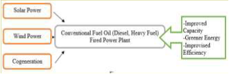
Rendering the consequence, this paper work emphasizes on mitigating the harmful effects of Oil fired power plant operating worldwide with greener energy. The non- replaceable plants might be an ideal option for practical implication of this paper work. The green energies segregated for the paper work are Solar Power, Wind Power and Cogeneration. These renewable energies will be additive to the oil fired plants without distracting the normal operational process of the plant. Greener energies might be treated as additional power resources improvising the oil fired plant’s performance capacity and/or efficiency. The below block diagram (Figure 1) provides the main focus of the paper work in simplest form possible.
Figure 1: Block Representation of Paper Work
The addition of solar and wind power will enhance the plant capacity in green methodology, whereas incorporation of renewable resource- cogeneration system will mitigate SOx, NOx and COx impacts on environment as well as reduce the fuel consumption by reducing fuel oil plant’s heat rate in an appreciable manner
IJSER © 2014 http://www.ijser.org
International Journal of Scientific & Engineering Research, Volume 5, Issue 7, July-2014
ISSN 2229-5518
1206
2 OBJECTIVE
The purpose of this paper is to design a fuel oil fired power station operated having extra output from used extracted heat, available space and emitted gas from chimney. The design comprises a HFO fired power plant model with generation capacity of 100 MW (Net) and additional capacity contribution from solar energy, wind energy and cogeneration.
1. To mitigate the environmental impacts of Fuel Oil fired power plant in conjunction of green energies such as solar system, wind energy and cogenerations.
2. To increment overall capacity as well as efficiency incorporating renewable energy resources without effecting the normal process flow of FO plant.
3. To analyze the theoretically calculated outputs and
simulation outcomes of individual renewable energy sources.
The above described main objectives/goals are achieved through following consideration:
I. The design incorporates solar panel to be placed at the roof top of power (engine) house occupying 37% of the entire plant area.
II. The emitted gas velocity from exhaust stack would be utilized to rotate a VAWT (Vertical Axis Wind Turbine) for improved efficiency.
III. Extracting the heat produced from IC (Internal Combustion) Engines and using the same to operate a steam turbine (referred to as ‘cogeneration’) for additional power output.
This model will have the provision to be edited and adapted to different improvisation as per requirement. The physical implementation depending on cost concession will provide accurate outcomes rather than simulated outings.
3 OPERATION OF OIL FIRED POWER PLANT
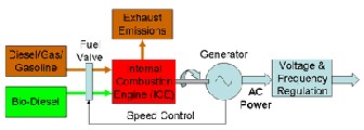
The power generation process is driven through two major parts i.e. internal combustion engines integrated with three phase synchronous generator, whereas the ICEs are operated through fuel oil injection acting as the main resource. The other parts comprising the smoother operation of the plant includes oil storage tank (fuel, lube), switch yard, transformers, pumps (water, injection etc.) and control panel (Gen-sets and protection system).
Figure 2: Operating Principle of Oil Fired Power Plant
The reciprocating engine with its compact size and its wide range of power outputs and fuel options is an ideal prime mover for powering electricity generating sets (gen-sets) used
to provide primary power in remote locations or more generally for providing mobile and emergency or stand-by electrical power. The internal combustion engine (ICE) is an engine in which the combustion of a fuel (normally a fossil fuel) occurs with an oxidizer (usually air) in a combustion chamber that is an integral part of the working fluid flow circuit. In an internal combustion engine the expansion of the high-temperature and high-pressure gases produced by combustion apply direct force to some component of the engine. [7]
Engine and alternator are mounted on a common steel foundation frame. An alternator is an electrical generator that converts mechanical energy to electrical energy in the form of alternating current [1]. For reasons of cost and simplicity, most alternators use a rotating magnetic field with a stationary armature but occasionally, a rotating armature is used with a stationary magnetic field; or a linear alternator is used. In principle, any AC electrical generator can be called an alternator. As described above, Figure 2 demonstrate the basic operation procedure of oil fired power plant.
4 APPLICABLE RENEWABLE ENERGIES
Among various renewable energies primarily three types’ i.e. solar, wind and cogeneration has been selected for main emphasizing and incorporating with fuel oil plant. The common phenomenon in between these three renewable energies are their ability to cope with existing system. Solar, wind and cogeneration power are easily extractable rather than other renewable sources such as Hydro, fuel cell, Biomass etc. The requirement for installation and maintenance works are also very flexible for solar and wind energy.
4.1 SOLAR ENERGY
Solar energy, at its most basic, is radiation generated by the sun that reaches the earth as light and heat. That energy can be converted into a usable form by man-made means. Solar technologies are broadly characterized as either passive solar or active solar depending on the way they capture, convert and distribute solar energy. Active solar techniques include the use of photovoltaic panels and solar thermal collectors to harness the energy. Passive solar techniques include orienting a building to the sun by selecting materials with favorable thermal mass or light dispersing properties. [8]

Solar power is the conversion of sunlight into electricity, either directly using photovoltaic (PV), or indirectly using concentrated solar power (CSP). [1]
Figure 3: Basic Ingredient of PV Cell
IJSER © 2014 http://www.ijser.org
International Journal of Scientific & Engineering Research, Volume 5, Issue 7, July-2014
ISSN 2229-5518
1207
PV converts light into electric current using the photoelectric effect. In brief, a material or device that is capable of converting the energy contained in photons of light into an electrical voltage and current is said to be photovoltaic (Figure
3). A photon with short enough wavelength and high enough energy can cause an electron in a photovoltaic material to break free of the atom that holds it. If a nearby electric field is provided, those electrons can be swept toward a metallic contact where they can emerge as an electric current. [9]
4.2 WIND ENERGY
A wind turbine (Figure 4) is a device that converts kinetic energy from the wind into electrical power. [6]
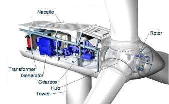
Figure 4: Different Parts of Wind turbine
Generating electricity from the wind requires that the kinetic energy of moving air be converted to mechanical and then electrical energy, thus the engineering challenge for the wind energy industry is to design cost- effective wind turbines and power plants to perform this conversion. The amount of kinetic energy in the wind that is theoretically available for extraction increases with the cube of wind speed. However, a turbine only captures a portion of that available energy. Power in wind is derived through following equation: Pw = ½ ρAv3
4.3 COGENERATION
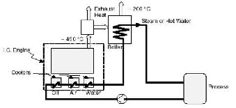
A cogeneration system is the sequential or simultaneous generation of multiple forms of useful energy (usually mechanical and thermal) in a single, integrated system. CHP systems consist of a number of individual components – prime mover (heat engine), generator, heat recovery, and electrical interconnection – configured into an integrated whole. [10]
Figure 5: Process Flow of Cogeneration System
Thermal energy from the reciprocating engines can be used in direct process applications or indirectly to produce steam, hot
water, hot air for drying, or chilled water for process cooling. facilities for power generation and CHP. The cycle is the basis for conventional power generating stations and consists of a heat source (boiler) that converts water to high-pressure steam. In the steam cycle, water is first pumped to medium to high pressure. A multistage turbine expands the pressurized steam to lower pressure and the steam is then exhausted either to a condenser at vacuum conditions or into an intermediate temperature steam distribution system that delivers the steam to the industrial or commercial application. The condensate from the condenser or from the steam utilization system returns to the feed-water pump for continuation of the cycle (Figure 5). [11] [12]
5 CAPACITY IMPROVEMENT CALCULATION
To evaluate the capacity improved through incorporation of solar, wind and cogeneration system, practical data from already operating 100 MW HFO Fired power plant will be considered. The general and required specification of a 100
MW HFO Fired power plant is given below: Total Plant Area : 34000 sqm Power House Area : 3200 sqm
No. of Generator Sets : 12
Power from each Genset : 8775 kW Engine Speed : 750 rpm
Fuel Oil Consumption : 192.7 g/kWh
Emitted Molecules : NOx, SOx, COx
[13] [14] [15] [16]
Net output from Solar Energy
For a 100 MW (Net) HFO Fired power plant module, Placement : Roof top of power house
Area : 3200 sqm
Solar module specification, Solar panel brand : SUNTECH
Area required : 1.626 sqm/each (1640 x 992 x 35 mm) Output per module: 260 W
Output from Solar Module, No. of panels : 1965
Total Output : 510,900 W or 510.9 KW
Net Output : 3,065,400 W/day or 127.725 KW/hr
(As solar cells remains 100% efficient up to 4 hours/day and
50% efficient for another 4 hours/day) [17]
Net output from Wind Energy
For a 100 MW (Net) HFO Fired power plant module, Placement : Horizontally fitted at the top of
Exhaust stack
No. of stack : 12
Diameter of stack : 1100 mm per stack
Area of stack : 0.95 m2 per stack
Gas emission data,
Exhaust emission velocity : 6.1 m/s Mass flow : 64.7 t/h Temperature at turbine outlet : 342 °C
SOx emission density : 1461.1 kg/m3
NOx emission density : 1447.58 kg/m3
IJSER © 2014 http://www.ijser.org
International Journal of Scientific & Engineering Research, Volume 5, Issue 7, July-2014
ISSN 2229-5518
1208
Air emission density : 1.225 kg/m3
Output from Wind Turbine, [P =1/2 x p x A x v3]
Total Output: 0.157 MW (15% for SOx) + 0.156 MW (15%
for NOx) + 132 W (70% for Air)
Net Output : 23550 KW + 23400 KW + 92.4 W
: 47.04 KW
For 12 stack net output: 0.5645 MW ± (5%) [18]
Net output from Cogeneration
For a 100 MW (Net) HFO Fired power plant module, [16]
[18] [19]
Exhaust gas flow in HRU (for one engine) : 66600 kg/hr
Exhaust gas temperature HRU (for one engine): 350 Deg. C
Thermal Input required for Steam Turbine (According to datasheet of TRIVENI),
Exhaust gas flow/engine : 18.5 kg/s Exhaust gas temperature IN : 350.0 0C Exhaust gas temperature OUT, ECO: APx200 0C Exhaust gas temperature OUT, LP : 194.9 0C Temperature in feed water tank : 135 0C Condensate temperature : 80.0 0C Condensate return % : 97.0 %
HP evaporating pressure : 16.1 bar
Steam pressure after super-heater : 16.0 bar
Output from Co-generation,
Steam flow per boiler : 3000 kg/h (As per Aalborg, ALFA LAVAL boilers)
Steam Temperature : 3050C
Steam Turbine Power : 3500 KW
Table 1: Calculated output tabulation
6 IMPLEMENTATION
To achieve the main objective, which is improvising efficiency through capacity enhancement of fuel oil fired power plant, one ambiguity arises as how to incorporate the renewable energies without distracting normal operation procedure of power station? Incorporation of solar, wind and cogeneration should be in a certain manner which only improves the capacity. Implementing the PV models, wind turbine and cogeneration should also balance out cost effectiveness in respect to generation capacity. Preconditions such as efficient utilization, operation non-distraction, environment friendliness etc. should be prime concerns during implementation of additive solar power, wind power and cogeneration. Focus should be emphasized on how much output is produced among these renewable energies individually and whether the achieved output is utilizable in the operational procedure of fuel oil fired power station. As a consequence, ideal implementation along with sufficient generation from additive source must be center consideration. [20] [21] [22]
6.1 INCORPORATING SOLAR POWER
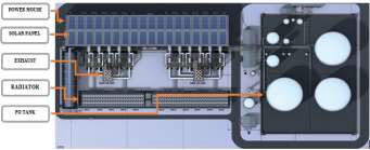
In context of Fuel Oil fired power plants, there are plenty of spaces which remains unutilized for maintaining safety precautions and also implementation of the said plant consume reasonable area. For utilizing these unused and/or idle spaces, incorporation of solar PV models would complement in an ideal manner. As a consequence, our first priority focuses on to discovery an unused space within the vicinity of fuel oil fired power station. The marked space should not cause distraction in the operation of power station and also to be focused to have sufficient sunlight for PV models.
Figure 6: Implementation of PV Array at Power House
Roof Top
An ideal place for the above described conditions would be the rooftop area of power house (Figure 6). Normally IC engines coupled with alternators are situated/installed in power house. The power house rooftop are locked down once IC engines and alternators are safely placed. Once locked out it remains in same manner until the operating life of power station. It has been estimated that, around 37% space of the entire plant is covered by power house. Therefore, placing PV models on the rooftop of power house not only demarcate ideal place to be utilized but also marks high enough place where sunlight’s availability will be undistracted.
6.2 INCORPORATING WIND POWER
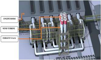
Certainly, power output of wind turbine depends on the wind velocity and availability of continuous wind speed. Three major concerns i.e. wind velocity, density of wind particles and tower height should be considered regarding placement of wind turbine. Greater wind velocity obviously will provide more output but subject to continuous availability of wind. So, wind turbine situated at higher position would definitely enhance the wind power.
Figure 7: Implementation of Improvised Wind Turbine at
Emission End of Exhaust Stack
IJSER © 2014 http://www.ijser.org
International Journal of Scientific & Engineering Research, Volume 5, Issue 7, July-2014
ISSN 2229-5518
1209

As discussed above, incorporation of wind power with fuel oil fired power plant would implicate tough challenge as the incorporation must not create disruption in daily generation procedure of the plant. Keeping in mind the early noted precondition, a suitable position for
installing the wind turbine should be selected. In fuel oil fired power plant, the most convincing position to install the wind turbines are at the top of exhaust stack (Figure 7). Preferably stack heights are high enough to overcome ground level air frictions and barrier from other obstacles for operating wind turbine. Noticeably oil fired
powers are normally implemented in certain rural areas with minimum civilization where wind flow is constant.
Nevertheless, taking into consideration the continuous emission of different molecules from exhaust stack, the velocity with which the molecules flow the surrounding wind velocity might be ignored. According to air dispersion module
carried out for several plant it was estimated that, NOx, SOx
and Air emission from each stack of fuel oil fired power plant has velocity of around 4-8 m/s for 55MW – 150MW generation capacity. With the velocity being sufficient enough, wind turbines might be placed horizontally with rotation around vertical axis. Therefore, edge of exhaust stack marks the ideal position for vertical axis wind turbine for wind power extraction, where different frictions are less and emission velocity is considerable enough.
6.3 INCORPORATING COGENERATION
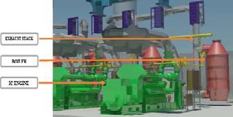
There are four sources of usable waste heat from a reciprocating engine: exhaust gas, engine jacket-cooling water, lube oil cooling water, and turbocharger cooling. With reciprocating (piston) engines approximately 34% of the heat input is recovered as power, and 66% is unrecovered. All of the heat rejected to the jacket water is recoverable along with, depending on the engine, approximately 40%-60% of the heat rejected to the exhaust outflow. In some instances, albeit rare, after cooler heat and lube oil can be recovered.
Figure 8: Cogeneration System Implementation
The waste or unrecovered heat (especially from exhaust outflow) is recovered by the cogeneration system (Figure 8) from above said engine oil, jacket, and exhaust heat. Captured heat is then used to burn the water injected from feed water pump and produce high pressurized steam flow within boiler. When high energy fluid (high pressure and high temperature) passes through series of rotor blades, it absorbs energy from fluid and starts rotating, thus it transforms thermal energy in
fluid to mechanical energy. So series of such blade which eventually transform thermal energy are the most vital part of a steam turbine.
7 SIMULATION & EXPERIMENTAL RESULTS
The practical incorporation of solar, wind and cogeneration system with an existing fuel oil fired power plant will be enforced to different constrains such as permit, budget, acceptance etc. To avoid the dilemmas and for authenticating the calculation based outcomes with practical implication MATLAB software would be ideal simulation tool. MATLAB deals with high-level language and interactive environment for numerical computation, visualization and programming. The power plant along with green energy incorporation modeling can be simulated in SimPowerSystem of MATLAB, which provides component libraries and analysis tools for modeling and simulating electrical power systems. SimPowerSystems models can be used to develop control systems and test system-level performance. [23] [24]
In order to avoid complexity and restrict different options, Heavy Fuel Oil (HFO) Power Plant of rated generation capacity of 100 MW has been considered for evaluating entire proposed model in simulation (Figure 9) [13] [14]. For 100
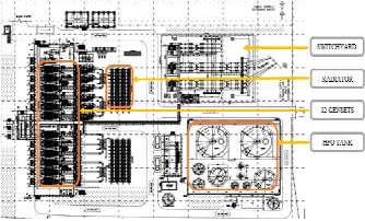
MW (Net) generation output at transmission end, 12 (Twelve) internal combustion engines having 8.75 MW rated output each coupled with three phase synchronous alternator has been considered. Each of the engine is interfaced with separate exhaust stack and air compressor system having an estimated heat rate of 8775 kJ/kWh. Synchronized 12 gensets along with HFO storage tank, cooling system and other major constructions are shown in the below figure:
Figure 9: 100 MWHFO Power Plant Layout
The energy sources i.e. oil, solar, wind and cogeneration system would be simulated together and addition output from green energy sources would be contacted and energizing a virtual replicate of in-house consumption. Also individual outputs from three renewable sources will extracted from simulation and accordingly compared with previously calculated output having similar data.
7.1 MODELING OF SIMULATION
In accordance to understand the overall behavior of individual energy simulation when incorporated together, a dummy load of 5MW has been used replicating in-house power
IJSER © 2014 http://www.ijser.org
International Journal of Scientific & Engineering Research, Volume 5, Issue 7, July-2014
ISSN 2229-5518
1210
consumption normally fetched in a 100MW oil fired power plant. The main source i.e. oil (HFO) has been utilized to provide power to three phase RLC load (which is used as replication of National Grid Demand). To conceive the in- house consumption a dummy load of 5MW has been extracted before providing power to RLC load and transformer. The addition renewable sources have been used to power up the in- house demand and accordingly made synchronous with existing internal load flow to evaluate whether the incorporation have any effect on the main load demand.
Instead of creating entire power plant simulation fired through oil, only one synchronous alternator was simulated as an alternative of 12 alternators having net output of 100 MW generation to complement the consider plant model generating output. The synchronous salient pole rotor type alternator having nominal power of 100 MW, line-to-line voltage 11 kV was governed by Diesel Engine Governor having simulation in per unit. A three phase 380 MW series RLC load has been considered to evaluate the outcomes in the scope after passing through 145 MW rated capacity transformer. [25] [26]
Simulation of solar power system comprises PV array for extracting solar irradiation and 3-level bridge inverter to convert DC generation from PV array to AC output. The series and parallel combination in PV array was conceived to match the 1965 panel outcomes as calculated to be placed above power house. The PV module specification selected for simulation is SUNTECH STP270S-24_Vb, where 72 numbers of cells comprises one module. Modules connected in series per string is 15 and parallel strings are 131, which equivalents to 1965 panels covering 3200 sqm rooftop area of power
house. The Three-Level Bridge block implements a three-level power converter that consists of one, two, or three arms of power switching devices. Each arm consists of four switching devices along with their antiparallel diodes and two neutral clamping diodes. The controlling of 3-level bridge inverter has been provided through Voltage Source Controller (VSC) which act Main Controller integrated with 3-phase voltage and current values along with Vdc for feedback purpose. The three- level VSC (blue blocks) regulates DC bus voltage at 500 V and keeps unity power factor. [27]
The simulation of wind power system has been conceived from ‘Wind Farm - Synchronous Generator and Full Scale Converter (Type 4) Detailed Model’ example. The wind turbine simulation consists of a synchronous generator connected to a diode rectifier, a DC-DC IGBT-based PWM boost converter and a DC/AC IGBT-based PWM converter. [28]
This wind turbine (Type 4) allows extracting maximum energy from the wind for low wind speeds by optimizing the turbine speed, while minimizing mechanical stresses on the turbine during gusts of wind. The wind speed is maintained constant at 6 m/s for 12 nos. of wind turbine, which has been also considered for calculation purpose. The control system of the DC-DC converter is used to maintain the speed at 1 pu. The reactive power produced by the wind turbine is regulated at 0 Mvar. Generator power for one turbine is 52kW with line- line voltage of 11kV having frequency maintained at 50Hz. Wind speed at nominal speed and at Cp max has been restricted in-between 6 m/s and 30 m/s with nominal mechanical output power fixed at 2MW.

Figure 10: MATLAB Simulation of Oil Fired Power Plant Incorporating Cogeneration, Wind Turbine and Solar Panel for
In-House Consumption

IJSER © 2014 http://www.ijser.org
International Journal of Scientific & Engineering Research, Volume 5, Issue 7, July-2014
ISSN 2229-5518
1211
Cogeneration system simulation comprises three major ingredients i.e. boiler, steam turbine and synchronous generator for mechanical to electrical conversion. The simulation outcomes were based on the data sheet of leading cogeneration manufacturing company – Aalborg (ALFA LAVAL) with TRIVENI turbine. In cogeneration system, boiler is essentially a closed vessel inside which water is stored. In case of fuel oil fired plant, heat extracted from IC Engines arise which comes in contact with water vessel where the heat is transfer to the water and consequently steam is produced in the boiler, whereas piping these generated steam to the turbine. In order to mitigate the simulation complexity, exhaust gas flow rate and temperature from a reciprocating engine (boiler input) is converted to boiler output along with pressure deviation according to datasheet reference of Aalborg, ALFA LAVAL. Simulation of turbine block comprises mathematical solutions interpreted to formulate turbine mechanical output through linking power and force equation. For equating turbine force, pressure extracted from boiler has been multiplied with boiler area having length, width and height data evaluated from TRIVENI datasheet. Product of steam flow rate from boiler and subsequent force provides power, which in comparison with temperature results in turbine mechanical output. For achieving electrical conversion a synchronous generator of 3.5 MVA rating along with required excitation system has been added. A RLC load has been added to compile the load flow. [16] [18]
7.2 RESULTS
The power output displayed for individual sources are present in the below figure 11:
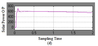
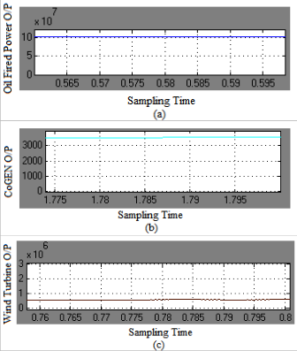
Figure 11: Simulation Results of (a) Oil Fired Power Plant (b) Cogeneration System (c) Wind Turbine System (d) Solar System
Power output from oil fired power plant remains undistracted to 100 MW which is evidence of the system stability regardless the incorporation. The simulation results displayed in the CoGEN scope reviles the power generation from synchronous generator is around 3.5 MW which is similar to our calculation based result. In case of wind turbine, simulation results displayed for power generation from wind turbine (12 nos.) is on average 556 kW which is close to our calculation based result of 564.5 kW. The output conceived from the solar power system stabilizes at around 547.63 kW in simulation outcomes having a closer result to calculated output (510.9 KW @ 100% irradiation).
To be noted that for wind turbine required value for modulation index "m" to obtain 1 pu generated voltage by the converter: m = Vnom * 2*sqrt(2/3) / Vdc. The power curve for all resources along with voltage and current curve initially takes few sampling time to reach the stabilized position. The power outcomes of simulation has been measured in Discrete Powergui format having sampling time of 2s.
Table 2: Comparison table between calculated and simulated outcomes.
Renewable Energy | Net Output (Calculation) | Net Output (Simulation) |
Cogeneration | 3500 KW | 3500 KW |
Wind | 564.5 KW | 556 KW |
Solar | 510.9 KW | 547.63 KW |
Total Output | 4.5754 MW | 4.6036 MW |
Efficiency Increased | 2.059% | 2.072% |
8 DISCUSSIONS & LIMITATIONS
During the entire processing of this paper, numerous observation and need for accuracy was encountered. The first obstacle faced was regarding the simulation of internal combustion engine powering alternator in SimPower to replicate entire power plant. The simulation of ICE engine are discretized powergui and required enormous pre-condition as modelled at SimDriveline. In addition, the complexity of simulation part increases in order to consider storage facility (i.e. battery) of solar output. In accordance, practical solar irradiation data (daily/monthly/yearly) was not conceived as it would arise complicacy in sampling and synchronizing the solar system with in-house load consumption of power plant. As for wind power system, commonly used wind turbine (i.e. HAWT) cannot be implemented on exhaust stack top, which
IJSER © 2014 http://www.ijser.org
International Journal of Scientific & Engineering Research, Volume 5, Issue 7, July-2014
ISSN 2229-5518
1212
implicates the use of specially designed horizontally placed
VAWT.
Unavailability of turbine and boiler arrangement in MATLAB tool eventually perceived for equating blocks constructed based on relevant equations. The turbine and boiler masks/blocks were built in such a way to sync with 3-phase generator. Although steam turbine bock was provided in Simulink library but it was design to govern the system, whereas the implemented blocks/masks were emphasized to be used with oil fired power plant. The incorporated simulation obviously required more accuracy in case of in- house power consumption as in-house consumption are basically from HFO & lube oil separator, pump, radiator, cooling system, preheater etc. Exact replication of entire power station would definitely provide the actual effectiveness of the entire incorporation system along with the simulation. Also per hour air dispersion data of exhaust stack and heat rate extraction of the ICE engine would have added to precision of the overall simulation and calculation.
The main limitation of this paper is the economic viability of the incorporated renewable sources. Solar panels are definitely expensive and wind turbine needs special design along with unconventional turbine setup system. The synchronization in- between all the energy sources would be major implication as prime outputs of all sources are different from each other.
9 FUTURE PLAN
This paper was conceptualized to mitigate harmful effects of existing fuel oil fired plant through incorporating greener energy which eventually contributes in generation capacities. The future expansion as well as practical implementation obviously requires more accurate assumptions and financial viability of said incorporation. The successful implementation would surely expand more ways of capacity improvement and additional renewable energy incorporation. In terms of incorporation, fuel cell might be an option for incorporation after improvising at different emission point. In addition solar and wind turbine might also be placed in other unused or landscaping areas for supplementary generation. In case of simulation, ICE engine can be incorporated with additional fuel consumption setup to actuate amount of heat produced in model. Afterwards it might be copped with cogeneration system to understand actual output of generation from steam turbine. Solar power simulation may be evaluated under yearly irradiation data for far more accuracy. Overall the addition generation might be connected to the in-house substation for contribution to national grid. These contribution will eventually add-up to net output of plant as well as minimize the expenditure for green energy incorporation.
10 CONCLUSION
The sole purpose of incorporation of renewable energy sources to existing plants not only is to enhance the capacity and volume of production. Rendering the consequences of the demand and detrimental effects on environment from pre- existing systems is something, the world sorely needs. Existing systems can be considered obsolete taking account its
total inability to comply with future generation scheme. Effects of continual utilization of such systems comprise health, environmental and political issues all across the world, steadily turning our planet into a ticking time bomb. Ideas presented in this paper simply suggests incorporation green energy systems, which are already individually established, to existing HFO systems without hampering current production. The resemblance between theoretical and simulation indicates convenience of practical implementation. Paper work envisions optional capacity improvement procedure with evident comparison and execution methodology. Such incorporation will undoubtedly provide enhancement production capacity at irreplaceable plants located in areas with serious electricity shortage concern rendering such plants more appreciable. Feasibility of the concept is highly adoptive and provides room for future development.
REFERENCES
[1] Wikipedia www.wikipedia.org
[2] RenewableEnergyWorld www.renewableenergyworld.com
[3] Power Score Card www.powerscorecard.org
[4] 2011 Sustainability Report www.thermofisher.com [5] Compare Electricity Cost and Review www.electricitywatch.org
[6] Renewable and Efficient Electric Power Systems;
Published by John Wiley & Sons, Inc., Hoboken, New Jersey. [7] Piston (Reciprocating) Engine Power Plants http://www.mpoweruk.com/piston_engines.htm
[8] PURE Sustainable Power www.purespower.com
[9] Photovoltaic Materials course.sdu.edu.cn
[10] Bureau of Industrial Cooperation (BICO) College of Engineering and Technology, University of Dar es Salaam Authored by: Dr. Enock Masanja
[11] Department of Energy, Queensland Government, Australia
[12] The European Association for the Promotion of
Cogeneration. www.cogen.org/
[13] CLC Power Company Ltd. 108 MW HFO Fired power plant, Washpur, Keranigonj. (MAN Diesel & Turbo Datasheet) www.maishagroup.com
[14] PowerPac Mutiara, 102 MW HFO power plant. Keranigonj
[15] MAN Diesel & Turbo, SE www.mandieselturbocom [16] Magnus Power Pvt. Ltd. www.magnuspower.com [17] SUNTECH solar system
[18] Alfalaval, Alborg, Finland, Steam Turbine Manufacturer Alfa Laval: Heat exchangers, Centrifugal separators, Pumps www.alfalaval.com/
[19] GE Triveni Limited www.triveniturbines.com/
[20] Making power plants energy efficient ABB, integrated power and automation solutions
[21] Mikko Hautio; ENVIRONMENTAL MANAGEMENT
PLAN FOR WÄRTSILÄ POWER PLANTS, Tekniikka ja
Liikenne, 2010
[22] T. K. Saha and D. Kastha, “Design optimization and dynamic performance analysis of a stand-alone hybrid wind- diesel electrical power generation system,” IEEE Transactions on Energy Conversion, vol. 25, no. 4, pp. 1209–1217, 2010.
IJSER © 2014 http://www.ijser.org
International Journal of Scientific & Engineering Research, Volume 5, Issue 7, July-2014
ISSN 2229-5518
1213
[23] Performance Analysis of Grid Integrated Hydro and Solar Based Hybrid Systems; Sweeka Meshram, Ganga Agnihotri, and Sushma Gupta
[24] T. Hirose and H. Matsuo, “Standalone hybrid wind-solar power generation system applying dump power control without dump load,” IEEE Transactions on Industrial Electronics, vol. 59, no. 2, pp. 988–997, 2012.
[25] SimPowerSystems Examples: Mechanical Coupling of Synchronous Generator with Exciter System; Gilbert Sybille, IREQ
[26] SimPowerSystems Examples: Synchronous Machine; Louis-A. Dessaint and R. Champagne (Ecole de Technologie Superieure, Montreal)
[27] SimPowerSystems Examples: Grid-Connected PV Array;
Pierre Giroux, Gilbert Sybille, Hydro-Quebec Research Institute (IREQ) Carlos Osorio, Shripad Chandrachood, (The Mathworks)- R2014a
[28] SimPowerSystems Examples: Wind Farm - Synchronous Generator and Full Scale Converter (Type 4) Detailed Model; Richard Gagnon and Jacques Brochu (Hydro-Quebec)
AUTHORS BIOGRAPHY
 Engr. Bony Francis Rozario: Engr. Bony Francis Rozario is on the verge of completing his Master’s degree in Electrical & Electronic Engineering from American International University Bangladesh (AIUB) having Power Engineering as Major. He has been serving as Assistant General Manager (Power Projects) from 2010 for a private
organization named ‘MAISHA GROUP’. He has completed his bachelor degree in Electrical & Electronic Engineering from American International University Bangladesh (AIUB). Afterwards, he perused his Internship at Siddirgonj Power Station, Bangladesh having a 210MW steam power plant and
2×120MW gas power plant). Email: bfrboss@gmail.com
 Dr. Mohammad Abdul Mannan: Mohammad Abdul Mannan was born in Laxmipur, Bangladesh on January 01, 1975. He received his B. Sc. Eng. Degree from Rajshahi University of Engineering and Technology (RUET former BITR), Bangladesh, in 1998, and Masters of Eng. and Dr. of Eng. degrees from Kitami Institute
of Technology, Japan, in 2003 and 2006 respectively, all in electrical engineering. He then joined in the American International University Bangladesh (AIUB) as an Assistant professor on May 2006. From July 2012 to November 2013 he was a senior Assistant Professor in AIUB. From December
2013 he is an Associate Professor in AIUB. Currently, he is appointed Head of Undergraduate Program. His research interests include electric motor drive, power electronics, power system, wind generation system and control of electric motor, power electronic converters, power system, and wind generation system.
IJSER © 2014 http://www.ijser.org