International Journal of Scientific & Engineering Research, Volume 4, Issue 9, September-2013 874
ISSN 2229-5518
Designing Of An Electrical Submersible Pump
Saurabh Kumar
Abstract — The Electrical Submersible Pump (ESP) system is considered as an effective and economical means of lifting large volumes of fluids from great depths, under a variety of well conditions. Over the years, the ESP companies, in conjunction with the major oil companies, have gained considerable experience in producing high viscosity fluids, gassy wells, high temperature wells, etc. W ith this experience and improved technology, wells that were once considered non-feasible for submersible's are now are being pumped economically. This paper is focused on the basic designing principles of an electrical submersible pump in conditions like High Water Cut, Gassy Wells, and High Viscosity.
Index Terms— Electrical Submersible Pump; Designing; High Water Cut; Gassy Wells; High Viscosity; High GOR Wells
—————————— ——————————
1 INTRODUCTION
ENTRIFUGAL pumps powered by downhole motors have been used for decades to lift fluids from oil wells. These pumps and their coupled motors are commonly referred to as “Electrical Submersible Pumps” or “ESPs”. In recent years, the meaning of the term “ESP” has become clouded with the application of downhole electric motors coupled to progressive cavity pumps. However, the industry still refers to the more conventional centrifugal pumping
equipment using the term “ESP”.
This paper outlines some of the classical considerations for analyzing, designing, and monitoring of downhole centrifugal pumps. The term “ESP” is always used as an abbreviation for “downhole centrifugal pump powered by a coupled electric motor”.
Experience has shown that proper design and application of ESP equipment rests on three pillars:
o Understanding the well’s productivity.
o Understanding the fluid ratios and phase behavior of
the fluids produced by the well.
o Careful analysis of activity in each stage of the actual installed pump.
Failure to accurately model the well’s inflow performance behavior will inevitably result in over-sizing or under-sizing the pump. In the absence of a variable frequency drive for ad- justing pump output, this can be disastrous. An oversized pump will “pump the well-off”. Typically, a “pump off” con- dition will trigger a “current underload” shutdown of the mo- tor. The well will remain “down” for referred to as “cycling”. Since startups create great strains on motors and pumps, cy- cling will often lead to premature equipment failure.
Conversely, an undersized pump will fail to achieve opti- mum production. Once this is detected, the equipment may have to be replaced. Regardless of whether the equipment is
————————————————
The author is currently pursuing B.Tech degree program in Petroleum Engineering in Indian School of Mines, University, India. MOB- +919006588443. E-mail: saurabhsuman1702@gmail.com
replaced, an undersized pump will significantly reduce the well’s rate of return (ROR).
The types of fluids being pumped, and the response of those fluids to changes in temperature and pressure have a tremendous impact on pump performance. Proper design and monitoring requires an accurate description of the Pressure- Volume-Temperature, and phase behavior of produced fluids.
Finally, the pump must be considered as a series of indi- vidual stages (or individual pumps). In many cases, each pump stage compresses the produced fluids and passes a dif- ferent volume (although same mass) of fluid to the next higher stage. This results in different head, break horsepower, and efficiency ratings for each stage of the pump.
In addition, it is crucial to analyze pump performance based on a “known good” condition. Experience has shown that each serialized pump demonstrates unique performance data. Therefore, a factory pump test should be obtained before the pump is installed in a well. The data from this test can be used throughout the equipment life for accurate performance analysis.
2 DESIGNING OF AN ELECTRICAL SUBMERSIBLE PUMP
Once a submersible unit has correctly been sized and its op- eration properly monitored, the installation becomes relatively trouble free and economical. The sizing procedures incorpo- rated in this section represent one of the methods of sizing submersible installations and do not necessarily represent all methods used in the submersible industry.
2.1 Basic Data Required while Designing:
It is appropriate to start this section on equipment sizing with a discussion of the data required for properly sizing an electrical submersible installation. The design of a submersible pumping unit, under most conditions, is not a difficult task, especially if reliable data is available. But if the information, especially that pertaining to the well's capacity, is poor the design will usually be marginal. Bad data often results in a misapplied pump and costly operation. A misapplied pump may operate outside the recommended range, overload or
IJSER © 2013 http://www.ijser.org
International Journal of Scientific & Engineering Research, Volume 4, Issue 9, September-2013 875
ISSN 2229-5518
underload the motor, or drawdown the well at a rapid rate which may result in formation damage. On the other extreme, the pump may not be large enough to provide the desired production rate.
Too often data from other wells in the same field or in a nearby area is used, assuming that wells from the same pro- ducing horizon will have similar characteristics. Unfortunately for the engineer sizing the submersible installations, oil wells are much like fingerprints, that is, no two are quite alike. Fol- lowing is a list of data required:
[1] Well Data:
o Casing or liner size and weight
o Tubing size, type and thread (new or used)
o Perforated or open hole interval
o Pump setting depth (measured and vertical)
[2] Production Data:
o Wellhead tubing pressure o Wellhead casing pressure o Test production rate
o Producing fluid level and/or well flowing pressure
o Static fluid level and/or static bottom-hole pres-
sure
o Datum point
o Bottom-hole temperature
o Desired production rate
o Gas-oil ratio
o Water cut
[3] Well Fluid Conditions
o Specific gravity of water
o Oil API or specific gravity
o Specific gravity of gas
o Bubble-point pressure of gas
o Viscosity of oil
o PVT data
[4] Power Sources
o Available primary voltage
o Frequency
o Power source capabilities
[5] Possible Problems
o Sand
o Deposition o Corrosion o Paraffin
o Emulsion
o Gas
o Temperature
The actual selection procedure varies significantly depending upon the production conditions and well fluid properties. It will be covered in subsequent sections for the following cases:
High-water-cut wells producing fresh water or brine.
Wells producing viscous fluids.
Wells with multi-phase flow (high GOR wells).
2.2 High Water-Cut Wells (ESP Installation)
This is the simplest type of well for sizing submersible equipment. The selection procedure is simple and straight forward and is based on the assumption that the produced fluid is incompressible, i.e., the specific gravity of fluid does not vary with pressure. In such a case, the following step-by- step procedure can be used:
1. Collect and analyze the available data as outlined above.
2. Determine production capacity, pump setting depth and pump intake pressure as required. Depending upon the data, several combinations are possible.
If the desired production rate and pump setting depth are known, the pump intake pressure at the desired production rate can be estimated based on the well in- flow performance. Otherwise, the optimum produc- tion rate for a given pump setting depth can be de- termined by plotting flowing pressure (or producing fluid level) - flow rate curve.
Unless there are special operating conditions, the pump is usually set close to the perforations (100-200 feet above perforations).
The drawdown may be limited to a point where the bottomhole producing pressure at the pump intake is higher than the bubble point pressure of the fluid to prevent gas interference.
In some cases (e.g., in water wells with high produc- tion rates), pump suction pressure requirements may become the limiting factor. However, in most of the cases, pump intake pressure of about 100 psig is ade- quate.
3. Calculate the total dynamic head required, which is equal to the sum of the net lift (vertical distance from producing fluid level to surface) friction loss in feet in production tubing and well head discharge pressure all expressed in terms of height of column of fluid be- ing produced.
IJSER © 2013 http://www.ijser.org
International Journal of Scientific & Engineering Research, Volume 4, Issue 9, September-2013 876
ISSN 2229-5518
4. Based on the pump performance curves, select a pump type so that the O.D. of the pump will fit inside the casing of the well and the desired production rate falls within the recommended capacity range of the pump. If two or more pumps meet these conditions, an economic analysis may be necessary before finaliz- ing the selection. In actual practice, the pump with the highest efficiency at the desired production rate is usually selected. From the selected pump perfor- mance curve, determine the head produced and brake horsepower required per stage. Calculate the number of stages required to provide the total dynamic head. The total number of stages rounded off to an integer is equal to the total dynamic head divided by the head produced per stage. Also calculate the motor horsepower by multiplying the brake horsepower per stage by the total number of stages and average spe- cific gravity of the fluid being pumped.
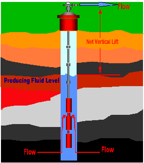
Figure No. 1: Figure Showing Reserervoir being pro- duced with the help of ESP and Net Vertical Lift.
5. Based on the technical information provided by the supplier, select appropriate size and model of the seal section and determine horsepower requirements. Se- lect a motor which is capable of supplying total horsepower requirements for both the pump and seal section. The selected motor should be large enough to withstand the maximum load without overloading it.
6. Using the technical data provided by the submersible pump manufacturer determine if any load limitations were exceeded (e.g. shaft loading, thrust bearing load- ing, housing pressure limitations, fluid velocity pass- ing the motor, etc.).
7. Select the power cable type and size based on motor current, conductor temperature, and space limita- tions. Calculate surface voltage and KVA require- ments.
8. Select accessory and optional equipment.
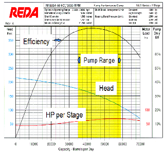
Figure No. 2: Pump Performance Curve of an ESP
2.3 Effect of High Viscosity Wells in ESP Installation
Most of the time, submersible pumps handle water or crude of relatively low viscosity. However, in some instances, submersible pumps are used to handle liquids whose viscosity is greatly different from water. Viscous fluids have high inter- nal resistance to flow. Consequently, the frictional losses and disk friction are increased which results in low head and high brake horsepower. Viscosity also has an effect on leakage loss- es and it has been found that the viscosity reduces the capacity of a pump at the best efficiency point.
The complete effect of viscosity on centrifugal pump behav- ior is still not entirely known, but recent laboratory tests con- ducted have added to our knowledge in evaluating the effects of various viscosities. New pump curves have been developed for each pump stage for handling liquids of varying viscosity. The Hydraulic Institute has also completed extensive tests and published standards on the determination of centrifugal pump performance when actual correction factors are unknown.
It has also been recognized that the water cut in some wells where viscous liquids are being handled affects the viscosity and must be taken into consideration. If an extreme viscosity, condition exists, it may be desirable to conduct laboratory tests prior to finalizing a pump size.
IJSER © 2013 http://www.ijser.org
International Journal of Scientific & Engineering Research, Volume 4, Issue 9, September-2013 877
ISSN 2229-5518
It is suggested that performance tests using the viscous liq- uids be conducted whenever facilities are available.
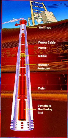
Figure No. 3: Schematic Diagram of an ESP
As described above, viscosity has a significant effect on cen- trifugal pump performance. The brake horsepower increases while head, capacity and efficiency decrease. If a submersible pump is to be used for producing high-viscosity fluids, with viscosity significantly differing from that of water, these ef- fects must be taken into consideration while selecting the equipment.
Viscous fluids in the oil industry are mainly due to either low gravity crude or formation of an emulsion. In the first case, the viscosity usually follows the well-established viscosi- ty temperature relationships and any of the empirical formu- las can be used for determining the viscosity at a given tem- perature and pressure. The problem is considerably compli- cated if the oil and water form an emulsion. The viscosity of the emulsion may be considerably higher than that of the con- stituents. Every emulsion behaves differently and there are few guidelines for determining the viscosity of an emulsion as a function of physical properties of the liquids. In such cases, it is recommended to perform laboratory tests to determine the behavior of the emulsion under simulated well conditions.
The submersible equipment for production of high-viscosity fluids can be selected by using the step-by-step procedure, described earlier for the case of high-water-cut wells, with a few modifications.
These modifications include:
1. Determine the gas-free crude viscosity at reservoir temperature from lab data or correlations.
2. Determine the gas in solution at the pump intake pressure with PVT data or correlations.
3. Correct the gas-free crude viscosity for gas saturation.
4. Convert viscosity units to SSU units.
5. Correct viscosity for water cut using lab test or data available.
6. Pump selection and correction factors are based on:
o Using the desired flow rate and casing size as pump selection criterion and
o Using the total fluid viscosity for determining the performance correction factors.
7. Determine total dynamic head as follows:
o Calculate net lift in same manner as for high- water-cut well.
o Calculate the friction loss in the discharge tubing by taking into account the actual viscosity of the fluid being produced.
o Convert wellhead pressure to height of liquid column.
o Calculate total dynamic head required by adding the above three components; net lift, friction loss and wellhead pressure.
8. Convert the desired production rate and total dynam- ic head into:
o "Pseudo" flow rate and
o "Pseudo" head by using the performance correc-
tion factors.
9. Using the pump performance curve:
o Determine the head/stage at this pseudo flow rate and calculate the number of stages required to produce the pseudo head.
o Calculate the total BHP required by using the pump performance correction factors.
o Select the additional equipment as necessary as described for the case of a high-water-cut well.
IJSER © 2013 http://www.ijser.org
International Journal of Scientific & Engineering Research, Volume 4, Issue 9, September-2013 878
ISSN 2229-5518
2.4 ESP installation in High GOR Wells
The presence of free gas at the pump intake and in the dis- charge tubing makes the process of equipment selection much more complicated and voluminous. As the fluid (liquid and gas mixture) flows through the pump stages from intake to the discharge and through the discharge tubing, the pressure and consequently, fluid properties (such as volume, density, etc.) continuously go on changing. Also, the presence of free gas in discharge tubing may create significant "gas-lift" effect and considerably reduce the required discharge pressure.
The performance of a centrifugal pump is also considerably affected by the gas. As long as the, gas remains in solution, the pump behaves normally as if pumping a liquid of low density.
However, the pump starts producing lower than normal head as the gas-to-liquid ratio (at pumping conditions) in- creases beyond certain "critical" values (usually about 10% ~
15%). It is mainly due to separation of the liquid and gas phas- es in the pump stage and due to a slippage between these two phases.
This phenomenon has not been well studied and there is, no general correlation describing the effect of free gas on pump performance. A submersible pump is usually selected by as- suming no slippage between the two phases or by correcting stage performance based on actual field test data and past ex- perience.
The following is a step-by-step procedure that is recom- mended when sizing an ESP system designed to produce liq- uid and gas mixtures:
1. Collect and analyze the available data.
2. Determine production rate, pump setting depth and pump intake pressure. If appropriate, use Vogel's IPR method to determine the flowing bottomhole pressure at the desired production rate. The pump intake pressure is calculated by correcting the flowing bottom-hole pres- sure for the difference between pump setting depth and datum point.
3. Determine the pump discharge pressure by using multi- phase flow correlations and PVT data.
4. Calculate the volume of oil, free gas and water at the pump intake using test data or the multi-phase correla- tions that best match your conditions. Calculate the per- cent of free gas to total volume offluids. If excessive gas is indicated, use separator and adjust the fluid volumes based on your selected gas separator efficiency.
5. Based on pump performance curves, select a pump capa- ble of handling the total intake volume and fit within the casing size requirements. Determine the head developed and motor load due to this stage by considering the com-
posite specific gravity of the fluids.
6. Calculate the number of pump stages required and de-
termine the BHP required. Select the appropriate seal sec-
tion, and if required, gas separator and calculate horse-
power requirements. Check for load limitations and se-
lect a motor to supply the needed horsepower.
7. Select the power cable type and size based on motor cur- rent, conductor temperature, and space limitations. Cal- culate surface voltage and KVA requirements.
If the solution gas/oil ratio (Rs), the gas volume factor (Bg), and the formation volume factor (Bo) are not available from reservoir data, they must be calculated. The most common correlations to select from for solution gas/oil ratio (Rs) and formation volume factor (Bg) are:
o Standing
o Vazquez and Beggs
o Lasater
o Glaso
The correlation you select will definitely affect your design, so select the one that best matches your conditions.
3. CONCLUSION
Multiple factors affect electrical submersible pump run life. To achieve a good electrical submersible pump run life, one needs first to understand the key factors that affect the system's run life and then effectively manage those factors.
ACKNOWLEDGMENT
I wish to thank Avinav Kumar, DySE (P), IOGPT, ONGC for his mastery & work which helped me in covering out this work smoothly.
REFERENCES
[1] “Electrical Submersible Pump analysis and Design” by Weather- ford published on 30th May 2001.
[2] ESP Handbook English (Centrilift) - Ninth Edition by Baker
Huges.
[3] Electrical Submersible Pumps Manual, Design, Operations and
Maintenance by Gabor Takacs.
[4] Fundamentals of Electrical Submersible Pumping in Oil Wells by
A.W. Grupping, Delft U. of Technology
[5] Electric Submersible Pumps by W.J. Powers, TRW Reda Pump
Division.
[6] Standard Handbook of Petroleum & Natural Gas Engineering.
ISBN 0-88415-643-5
[7] Lyons, William C., ed. (1996). Standard Handbook of Petroleum & Natural Gas Engineering 2 (6 ed.). Gulf Professional Publish- ing. ISBN 0-88415-643-5
[8] Other forms of artificial lift include Gas Lift, Beam Pump- ing, Plunger Lift and Progressive cavity pump.
IJSER © 2013 http://www.ijser.org