International Journal of Scientific & Engineering Research Volume 2, Issue 6, June-2011 1
ISSN 2229-5518
Design of Viterbi Decoder for Noisy Channel on FPGA
Ms. M.B.Mulik, Prof. U.L.Bombale, Prof. P.C.Bhaskar
Abstract— The problem of survival memory management of a Viterbi Decoder (VD) was solved by introducing a pointer implementation for the register exchange (RE) method, where a pointer is assigned to each row of memory in the SMU. The content of the pointer which points to one row of memory is altered to point to another row of memory, instead of copying the contents of the first row to the second. In this paper, the one- pointer VD is proposed; if the initial state of the convolutional encoder is known, the entire survivor memory unit (SMU) is reduced to only one row. Because the decoded data are generated in the required order, even this row of memory is dispensable. Thus, the one-pointer architecture, referred to as memory less Viterbi Decoder (MLVD), reduces the power consumption of a traditional trace back (TB) VD by approximately 50 percent. A prototype of the MLVD with a one third convolutional code rate and a constraint length of nine is mapped into a Xilinx.
Index Terms—wireless, low power, Viterbi Decoder, register exchange, memory less.
—————————— • ——————————
1. INTRODUCTION
HE Viterbi Algorithm is an efficient method for the realization of maximum likelihood decoding of convolutional codes [2],[3]. The digital VD is widely used in many digital wire line and wireless applications. Existing VDs are categorized by the way how the decoded data bits are stored in and retrieved from the SMU. Two methods are mainly used, the RE and the TB method [4]. In the literature, the RE method is acceptable for trellises with only a small number of states, whereas the TB approach is acceptable for trellises with a large number of states. Therefore, the TB method has been widely investigated and implemented. Although several attempts to reduce the power consumption of the TB VD have been proposed, only a few attempts to combine the advantages of the TB and RE methods have been
reported.
The modified RE method [1], which is further improved in this work, utilizes the pointer concept, that is widely used in software engineering. Instead of moving the contents of one row of memory to a second row of memory, the pointer to the first row is altered to point to

• Ms M.B.Mulik is currently pursuing master degree program in
Electronics Technology in Shivaji University, Kolhapur, India,PH-
09921660850, Email-mulik_madhuri2002@yahoo.co.in, Sponsored by
Shard Institute of Technology, Polytechnic, Yadrav.
• Dr.U.L.Bombale is currently working as a Professor in Electronics Technology in Shivaji University, Kolhapur, India, PH-09049274380, Email-uttam_bombale@rediffmail.com.
• Prof.P.C.Bhaskar is currently working as a M.Tech Co-Coordinator in
Electronics Technology in Shivaji University, Kolhapur, India, PH-
09881248133, Email- pxbhaskar@yahoo.co.in
the second row. The pointer to one row of memory simply carries the current state in the trellis of the VD. The pointer implementation avoids the power hungry register exchange operations of the traditional RE method, and is referred to as pointer Viterbi Decoder (PVD). In the next section the PVD is briefly reviewed, and then its memory less version is introduced.
2. THE MEMORYLESS VITERBI DECODER (MLVD)
The PVD keeps track of the current row position of the decoder in the memory. It makes use of the fact that the bit appended to each row of memory is exactly the bit that is shifted into the pointer to form the new pointer to that row of memory. To show the functionality a 4-state rate=1/3 convolutional encoder (G0=101, G1=111, and G2=111) is employed to encode the input sequence of (10110100100). The code stream, (111, 011, 000, 100, 100,
000, 011, 111, 111, 011, 111) is generated and transmitted
over a noisy channel. The noisy code stream, (111, 011,
001, 100, 100, 000, 011, 111, 110, 011, 111), for example, is received at the decoder. The underlined bits are incorrect because of the noise encountered during transmission. Applying the modified RE method results in the diagram illustrated in Figure. 1. This figure displays the successive values for the pointers and rows of memory over time.
A closer look reveals that each row of memory is
used to trace the decoded bits, if an initial state is assumed. The first row of memory decodes the data, if an initial state, S0, is assumed. The last row records the decoded data, if an initial state, S255, is assumed, and so on. If the initial state is known, are all these rows of memory necessary? Absolutely not. For example, if the initial state is zero, then only the first row of memory is
IJSER © 2011
http://www.ijser.org
International Journal of Scientific & Engineering Research Volume 2, Issue 6, June-2011 2
ISSN 2229-5518
needed. In other words, the storage of the decoded bits is necessary in order to choose only one row of memory at the end to represent the actual decoded bits. If the
required row of memory is predetermined, then there is
no need for the storage of the other rows. Furthermore, there is no need for the storage of the row that is assigned to the predetermined
Fig. 1. New RE approach with pointer implementation (the upper register carries the pointer
and the lower register carries the decoded bits)
then there is no need for the storage of the other rows.
Furthermore, there is no need for the storage of the row that is assigned to the predetermined initial state, because the RE approach generates the decoded bits in the correct order. The decoded bits are produced, and then read out from the decoder.
Thus, a memory free Viterbi decoder can be implemented by solely resetting the encoder contents for each L bits that are encoded. There is no need to interrupt the data sequence or to transmit a long sequence of zero data bits. The encoded data is continuous, but the contents of the encoder bits (eight bits for K = 9 convolutional encoder) are reset to zero for each L bits transmitted. The only overhead for such an implementation in a communication system is to synchronize between the transmitter and the receiver. The new VD implementation is called, the Memory Less Viterbi Decoder (MLVD). Since the MLVD needs to track only one row, the MLVD requires only one pointer to track the current position of the decoder in the trellis in Figure. 2.
Fig. 2. MLVD approach with pointer implementation (the upper box carries the pointer and the lower box carries the decoded bits)
The MLVD is an extra low power design or a VD with the only restriction of resetting the encoder register at each L of the encoded data bits and providing the necessary synchronization. The block diagram of the
MLVD, designed in VHDL, is shown in Figure .3.
Fig. 3. MLVD block diagram
2.1 Convolutional Encoder
The convolutional encoder that is implemented is shown in Figure 4 It is a K=9 and r=1/3 convolutional encoder. Figure. 4. Shows the block diagram of the convolutional encoder. Three outputs are generated for each bit encoded. To implement a hard-decision VD, The output of the encoder is fed directly into the first block of the VD, the BMU.
2.2 Branch Metric Unit (BMU)
In the VA for decoding convolutional codes, however, for binary convolutional codes, it is proven that linear distances (Hamming distances) can be used as the optimum branch metrics. For three 3-bit hard decision input bits, (i0, i1, i2), each branch metrics are generated.
IJSER © 2011
http://www.ijser.org
International Journal of Scientific & Engineering Research Volume 2, Issue 6, June-2011 3
ISSN 2229-5518
The | BMU performs | simple | add | and | subtract | necessitates two 8-bit registers for each PM to |
| temporarily store the two calculated PM values which |
| are compared in the ACSU so that the smaller one can be |
| chosen as the new PM. In addition, extra registers are |
| required to store the carry bits that are generate during |
| the addition and subtraction operations in the ACSU. A |
| very simple shifter is introduced which requires only one |
| control signal and is composed of eight master latches. |
Fig. 4. Convolution encoder
operations on the decision bits to generate the output. The BMU performs the computations, as represented in Figure. 5. The bit serial format of the branch metrics is generated by the parallel to serial module at the output of the BMU the BMs is then fed into the ACSU. As shown in Figure. 5. The bit serial format of the BMs is then fed into the ACSU.
Fig. 5. Branch Metric Unit (BMU) operations
2.3 Add Compare Select Unit (ACSU)
The ACSU is composed of 128 units; each is composed of an ACS butterfly module, as shown in Figure 6.
Fig. 6. One ACS butterfly module
2.3.1. Bit Serial ACS Architecture
The block diagram for one ACSU is displayed in Figure.
7. The bit serial approach significantly reduces the interconnection load, but does not allow for the reformulation of the ACS functions. Thus, the traditional addition and subtraction operations are performed in the
bit serial ACSU. However, the bit serial approach
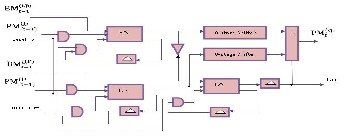
Fig. 7. Bit Serial ACS Architecture
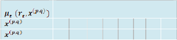
2.3.2 Butterfly structure of the ACS

Fig. 8. Butterfly structure of the ACS
For example, if both paths from state j are considered to be survivor paths for the destination states p and q, the BMs of both paths are compared. Then the pointer, which carries the value j, changes to the destination pointer, whose path has the smaller BM. The pointer of i changes to the other destination pointer, while the path from state i receives a termination high signal. This indicates that the path from state i is terminated, and the decision bits are no longer appended to the path’s register. Consequently, only the pointer value of the terminated path will continue to be modified in order to prevent the presence of duplicated pointer values.
The ACSU is composed of 126 units; each is composed of an ACS butterfly module which adds the BMs to the corresponding path metrics (PMs), compares the new PMs, and then feeds the selected PMs Back into the ACSU. The typical operation of one ACS butterfly module is as follows:
IJSER © 2011
http://www.ijser.org
International Journal of Scientific & Engineering Research Volume 2, Issue 6, June-2011 4
ISSN 2229-5518
If


Then  = 0
= 0


If


Then  = 1
= 1


If 


Then  = 0
= 0


If 


Then = 1


And according to the symmetric characteristics of the VD

 =
=
and  =
= 
Therefore, only two branch metrics BMs are connected to each butterfly unit as shown in Figure
4.8.The bit serial approach for the MLVD implementation to reduce the routing overhead among the different ACSU modules. The routing among the different ACSU modules represents an overhead, which is left for the automatic optimization of the FPGA router.
2.3.3 Branch Metric

For Hard-decision metric,  can be computed in advance. For example, for an n = 3 binary code, there are eight possible received values, 000, 001,
010, 011, 100, 101, 110, 111, & eight possible transmitted values. The metric is an 8 × 8 array, such as following Table 1 shows,
Table 1
Branch Metric
= 010
= 011
= 100
= 101
= 110
= 111

2.4 Add Compare Select TO Survivor Memory
(ACSTOSM)
The ACSTOSM is employed to route the decision of the appropriate ACS module to the output. The ACSTOSM is a 256 to one decoder. The select signal for this large decoder is the output of the pointer module. The output of the ACSTOSM module is already the decoded output sequence of the VD, but is fed back into the pointer module to update the current state in the decoding trellis.
2.5 Pointer
The pointer block contains the current state of the decoder (eight bits). For each bit decoded, the pointer content is updated. The exact position of the bit that will be updated is determined by the MSB block.
2.6 Most Significant Bit (MSB)
The MSB block has eight outputs that point to the eight bits of the pointer in parallel. At the reset, the eighth bit of the MSB block is enabled which, in turn, causes the eighth bit of the pointer to be the most significant bit. After accessing an incoming code word in the ACSU, a decision bit is written into the MSB of the pointer, and the output of the MSB block is shifted to the right so that only the seventh bit is enabled. For the pointer, this indicates that the seventh bit is now considered to be the most significant bit. In this case, pointer P should be read in the following order: P6P5P4P3P2P1P0P7, instead of the usual order: P7P6P5P4P3P2P1P0. This process continues with each incoming code word.
3. Comparison of the memory/register operations to decode codeword for various VD methods
Table 2
Comparison of various VD methods

Operation TB (48) Modified RE (48)
MLVD (168)
= 000
= 001
Writing decision bits into the
256 x 48
12288w
6144w –
IJSER © 2011
http://www.ijser.org
International Journal of Scientific & Engineering Research Volume 2, Issue 6, June-2011 5

ISSN 2229-5518
memory
Reading from the memory
48 x 3 r
72w
48r/2 –
24w
Writing into the MSB of the pointers
Writing the termination bits into
the termination
registers
– 256 x 48 rg
1536w
– 256 rg
32 w
168rg
21w
–
8-bit register shifting (shift to the right and append a bit to the
LSB)
48 x 3 x 8rg – –
144w
Fig. 9. Simulation result of MLVD using modelSim
Total 12504w 7736w 21w
Where,
W = writing one bit into the memory block
r = reading one bit from the memory block
rg = writing one bit into a register
4. Simulation result of VD using modelSim
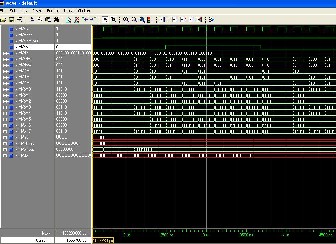
Simulation of MLVD is did using XILINX ISE simulator and corresponding results shown in figure 9. Simulation is done using command line of modelSim. Using commands provided by modelSim it is possible to force signal to desired value for required amount of time. Initially required signals are added into waveform window of modelSim and inputs ate forced using commands.
Figure. 9. Shows the VD output which is corrupted
by eb1 error signal, whenever eb1 signal goes high it introduces error. Figure .10. Shows decoder output ‘dom’ i.e. sequence 011 110 001 000 010 000 that becomes 010
111 000 001 011 001 means each last bit of decoded output goes into error.
But using trellis diagram the branch metric calculated from that minimum path metric selected in viterbi decoder so that the error is corrected as shown in figure 10. In this waveform shows viterbi decoder corrected that corrupted data.
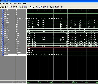
Fig. 10. Simulation results of MLVD shows corrupted data is recovered back to original data
5. Conclusion
In this work, error detection and correction techniques have been used which are essential for reliable communication over a noisy channel. The effect of errors occurring during transmission is reduced by adding redundancy to the data prior to transmission.
A MLVD based on FPGA is proposed and implemented in this work .The MLVD is a memory less implementation of the VA, and successfully decodes the continuous data encoded by a convolutional encoder and synchronizing the VD with the resetting procedure. The new implementation is realized by applying the pointer
concept to the RE implementation, and by reinforcing the
IJSER © 2011
http://www.ijser.org
International Journal of Scientific & Engineering Research Volume 2, Issue 6, June-2011 6
ISSN 2229-5518
initial state of the convolutional encoder every L bits encoded. The hardware and computational overhead of the new implementation is only a 256 to 1 decoder, which is switching at the data rate frequency. The new MLVD is a memory less high speed, low latency, and low power variation to the VD
ACKNOWLEDGMENT
This work would not have been possible without the encouragement and able guidance of Dr. U. L. Bombale. SUK, Kolhapur. Their enthusiasm and optimism made this experience both rewarding and enjoyable. Most of the novel ideas and solutions found in this thesis are the result of our numerous stimulating discussions. His feedback and editorial comments were also invaluable for the writing of this thesis.
I am grateful to coordinator department of electronics Prof. P. C. Bhaskar for providing the facilities for the completion of thesis.
I wish to acknowledge and thank to my family
and friends, especially to my parents, for their support, without which I couldn’t have completed this work.
REFERENCE
[1] D. A. El-Dib and M. I. Elmasry, “Modified register- exchange viterbi decoder for low-power wireless communications,” IEEE Transactions on Circuits and Systems I, vol. 51, no. 2, pp. 371-378, February 2004.
[2] A. Viterbi, “Error bounds for convolutional codes and asymptotically optimum decoding algorithm,” IEEE Transactions on Information theory, vol. It-13, no. 2, pp.
260–269, April 1967.
[3] G. Forney, “The viterbi algorithm,” Proceedings of the
IEEE, vol. 61, no. 3, pp. 268–278, March 1973.
[4] S. B. Wicker, Error Control Systems for Digital
Communication and Storage. Prentice Hall, 1995.
[5] J. H. et al, “Cdma mobile station modem asic,” IEEE Journal of Solid- State Circuits, vol. 28, no. 3, pp. 253-
260 March 1993.
[6] I. Kang and A. W. Jr, “Low-power viterbi decoder for cdma mobile terminals,” IEEE Journal of Solid-State Circuits, vol. 33, no. 3, pp. 473- 482, March 1998.
[7] Inyup Kang, Member, IEEE, and Alan N. Willson Jr.
Fellow IEEE.”Low-Power Viterbi Decode for CDMA
mobile terminals” Ieee journal of solid-state circuits
, vol.33, no. 3, march 1998,
[8] James Tang and Esam Abdel-Raheem “High Speed
Viterbi Decoder Design and FPGA
Implementation” .Department of Electrical and Computer Engineering , University of Windsor, Ontario, Canada N9B 3P4.
[9] C. B. Shung et al., “Area-efficient architectures for the Viterbi algorithm Part I: Theory,” IEEE Trans. Commun., vol. 41, pp. 636–644, Apr. 1993.
[10] S.-S. Wang, “A state-reduction viterbi decoder for convolutional codes with large constraint lengths,” Master’s thesis, National Chiao Tung University, Hsinchu, Taiwan, June, 2002
[11] H.-L. Lou, “Linear distances as branch metrics for viterbi decoding of trellis codes,” Proc. IEEE International Conference on Acoustics, Speech, and Signal Processing, vol. 6, pp. 3267-3270, June 2000
[12] R. Henning and C. Chakrabarti, “Low-power approach for decoding convolutional codes with adaptive viterbi algorithm approximations, ”Proc. IEEE International Symposium on Lower Power Electronics and Design, pp. 68-71, August 2002.
IJSER © 2011
http://www.ijser.org