International Journal of Scientific & Engineering Research Volume 2, Issue 4, April-2011 1
ISSN 2229-5518
Design of Boost Circuit for Wind Generator
N.Prasanna Raj, M.Mohanraj, Rani Thottungal
Abstract— This paper presents the design and implementation of a power converter for an autonomous wind induction generator (IG) feeding an isolated load through the PW M-based novel soft-switching int erleaved boost convert er. The output voltage and frequency of the wind IG is inherently variable due to random fluctuation of wind-speed variation. The int erleaved boost converter composed of two shunt ed element ary boost conversion units and an auxiliary inductor. This convert er is able to turn on both the active power switches at zero voltage to reduce their switching losses and evidently raise the conversion efficiency. Since the two parallel-operated elem entary boost units are identical, operation analysis and design for the converter module becomes quite simple. A three-phase induction machine model and a three-phase rectifier-inverter model based on a-b-c reference frame are used to simulate the performance of the generation system. It can be concluded from the sim ulated results that the designed power converters with adequat e control scheme can effectively improve the performance of output voltage and frequency of the IG feeding an isolated load.
Index Terms— wind power generator, rectifier-invert er circuit, pulse width modulation (PW M), interleaved boost convert er, soft switching.
—————————— • ——————————
1 INTRODUCTION
HE characteristics of induction generator (IG) with an externally connected capacitor bank have been extensively explored for over 60 years since 1935 [1].
Due to the fast development of environmental protection
concepts, the regenerative or renewable energy sources
have been significantly and widely studied and evaluated in the whole world. The primary merits of IG over a conventional synchronous generator are brushless
construction with squirrel-cage rotor, small size, without
DC supply for excitation, less maintenance cost, and better transient performance. The IGs have been extensively utilized as suitable isolated power sources in small hydroelectric, tidal, and wind energy applications at the remote sites, rural areas, or developing countries [2 – 4]. The performance of IG supplying various static loads using different control schemes are studied and analysed in various papers. The control schemes proposed so far divides into three categories. The most economic method is by means of switching series and/or parallel capacitors connected to the IG stator winding or load side for voltage regulation. The primary disadvantage of this scheme is that the equivalent capacitance is changed in discrete form and the voltage cannot be effectively and linearly regulated. Though the voltage magnitude is controlled to a certain constant level, the output frequency of the controlled IG is significantly varied with the rotor speed. The second method is to modulate the absorbed reactive power of the IG whose stator windings is directly connected to the load and the reactive power compensator. Although the terminal voltage of the stator winding can be effectively controlled, the frequency variation problem due to random fluctuation of rotor speed is similar to the one of the first
method. The third method is the most effective control scheme, which can control both voltage and frequency of the IG within a specified level by using power electronic converters such as a rectifier-inverter module (AC-to-DC and DC-to-AC converters).
Boost converters are usually applied as preregulators or
even integrated with the latter-stage circuits or rectifiers
into single-stage circuits [5 – 9]. Most renewable power
sources, such as photovoltaic power systems and fuel cells,
have quite low-voltage output and require series
connection or a voltage booster to provide enough voltage
output. Several soft-switching techniques for dc/dc converters have been proposed. The main problem with these kinds of converters is that the voltage stresses on the power switches are too high in the resonant converters, especially for the high-input dc-voltage applications. Interleaved boost converters are applied as power-factor- correction front ends. An interleaved converter with a coupled winding is proposed to provide a lossless clamp. Additional active switches are also appended to provide soft-switching characteristics [10 – 13]. These converters are able to provide higher output power and lower output ripple. This paper proposes a soft-switching interleaved boost converter composed of two shunted elementary boost conversion units and an auxiliary inductor. This converter is able to turn on both the active power switches at zero voltage to reduce their switching losses and evidently raise the conversion efficiency [14], [15]. Since the two parallel-operated boost units are identical, operation analysis and design for the converter module becomes quite simple.
IG fed to an isolated load through the employment of a PWM based closed loop boost converter with controlled inverter is presented. The simulated performance of the
IJSER © 2011 http://www.ijser.org
International Journal of Scientific & Engineering Research Volume 2, Issue 4, April-2011 2
ISSN 2229-5518
proposed control scheme is employed to design a PWM controller for the boost converter and inverter. The implementation and design of a power converter for an autonomous wind induction generator (IG) feeding an isolated load through the PWM-based boost-inverter circuit is simulated here.
2 METHODOLOGY
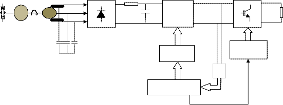
The generation system is designed with IG. The stator winding terminals of the IG are connected to the load through the rectifier, DC link, Boost circuit and inverter. The closed loop PWM signal generates proper PWM signals to switch the 2 power electronics devices of the Interleaved Boost Converter (IBC). The wind turbine rotates the IG. The IG generates power when the speed of the turbine is above the rated speed. The power generated from the IG is converted to DC with a diode bridge rectifier. The obtained DC voltage will not be in a pure DC signal. A filter circuit is used to filter out the ripple current and a pure DC voltage is obtained. This DC voltage is then boosted to the required DC level and then converted to three phase AC signal with IGBT which is driven by PWM signal. To regulate the AC output voltage the IBC is controlled by close loop PWM signals. A load is connected at the output of the inverter. The voltage-current equations of the studied IG in matrix form are listed as below.
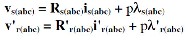
Where Rs(abc) and R'r(abc) are respectively the resistance matrices of the stator and rotor windings and As(abc) and A'r(abc) are respectively the flux-linkage matrices of the stator and rotor windings [16].
The expression of the output power is
Pm=0.5pAV3Cp
- Pm: Mechanical output power of the turbine (W),
- Cp: Performance coefficient of the turbine,
- p: Air density (Kg/m3),
- A: Turbine swept area (m2),
- V: Wind speed (m/s).
Pulse-width modulation (PWM) is a very efficient way
of providing intermediate amounts of electrical power
between fully on and fully off. A simple power switch with
a typical power source provides full power only when
switched on. The term duty cycle describes the proportion
of on time to the regular interval or period of time; a low
duty cycle corresponds to low power, because the power is

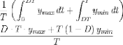
off for most of the time. Pulse-width modulation uses a rectangular pulse wave whose pulse width is modulated resulting in the variation of the average value of the waveform. If we consider a pulse waveform f(t) with a low value ymin, a high value ymaxand a duty cycle D, the average value of the waveform is given by


As f(t) is a pulse wave, its value is ymax for 0<t<D.T
and ymin for D.T<t<T The above expression then becomes


The simplest way to generate a PWM signal is the interceptive method, which requires only a sawtooth or a triangle waveform and a comparator. When the value of the reference signal is more than the modulation waveform, the PWM signal is in the high state, otherwise it is in the low state.
IG Wr
Wind Turbine
Ce
Convert L
Cdc
IBC
PWM Driver
Inverter
PWM Gating Signal
Load
DSPIC
Fig1 Block Diagram
IJSER © 2011 http://www.ijser.org
International Journal of Scientific & Engineering Research Volume 2, Issue 4, April-2011 3
ISSN 2229-5518
Fig 2 Interleaved Boost Converter
Fig.2 shows the proposed soft-switching converter module. Inductor L1, MOSFET active switch S1 and diode D1 comprise one step-up conversion unit, while the components with subscript “2” form the other. Dsx and Csx are the intrinsic antiparallel diode and output capacitance of MOSFET Sx, respectively. The voltage source Vin, via the two paralleled converters, replenishes output capacitor
Fig 3 IBC Study
C0 and the load. Inductor Ls is shunted with the two active MOSFET switches to release the electric charge stored within the output capacitor Csx prior to the turn-ON of Sx to fulfill zero-voltage turn- ON (ZVS), and therefore, raises the converter efficiency. To simplify the analysis, L1, L2 and C0 are replaced by current and voltage sources, respectively, as shown in Fig. 3.
The proposed circuit is focused on higher power demand applications. The inductors L1 and L2 are likely to operate under continuous conduction mode (CCM); therefore, the peak inductor current can be alleviated along with less conduction losses on active switches. Under CCM operation, the inductances of L1 and L2 are related only to the current ripple specification. What dominates the output power range and ZVS operation is the inductance of Ls.
3 CIRCUIT OPERATION ANALYSIS
Before analysis on the circuit, the following assumptions are presumed.
Fig 4. Modes of Operation of IBC
1) The output capacitor C0 is large enough to reasonably neglect the output voltage ripple.
IJSER © 2011 http://www.ijser.org
International Journal of Scientific & Engineering Research Volume 2, Issue 4, April-2011 4
ISSN 2229-5518
2) The forward voltage drops on MOSFET S1, S2 and diodes D1 and D2 are neglected.
3) Inductors L1 and L2 have large inductance, and their currents are identical constants, i.e., IL1=IL2=IL.
4) Output capacitances of switches Cs1 and Cs2 have the same values, i.e., Cs1=Cs2=Cs.
The two active switches S1 and S2 are operated with pulsewidth-modulation (PWM) control signals. They are gated with identical frequencies and duty ratios. The rising edges of the two gating signals are separated apart for half a switching cycle. The operation of the converter can be divided into eight modes, and the equivalent circuits and theoretical waveforms are illustrated in Fig. 4.
The project module is simulated using MATLAB
7.7.0(R2008b). The simulation is executed under ode23tb (stiff/TR-BDF2) state which is used to fasten the execution speed and the Zero-crossing control is disabled. The solver
method is set to fast. The voltage is measured at different points in the simulation circuit. The simulated output is shown below. The system is tested with different load and
wind speed. The designed system generates AC power with asynchronous generator (215HP; 400V; 50Hz). The utilizes a three-phase asynchronous machine model and a
three-phase rectifier-inverter model based on a-b-c reference frame to simulate the performance of the generation system. The IG design is made with the calculated value of resistance, flux linkage of the stator and rotor windings and with the torque equation and the number of poles. The generated power is rectified. The generated power varies with the wind speed. The power converter converts the three phase AC to DC and then the filter circuit is used for obtaining smooth DC voltage across it. This DC voltage is then boosted with the interleaved boost converter (IBC). Theoretically IBC can boost up to
200%. The DC voltage is fed to the inverter before which it
is regulated to desired voltage in a closed loop with PWM technique. Thus the output at the IBC is always constant – rated voltage. This DC voltage is then regulated AC three phase with IGBT’s. An IGBT inverter is designed with a open loop PWM technique and feed the AC load. PWD signal is designed in close loop and open loop system with PID and PI controller respectively. The PWM signal is generated to regulate the DC voltage that in turn gives a fixed AC supply from the inverter. Thus a regulated Three Phase AC supply is transmitted to the Load.
4 RESULTS AND DISCUSSIONS
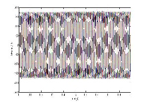
Fig 5 Input voltage 160V AC
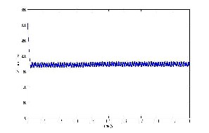
Fig 7 Rectified DC 160V
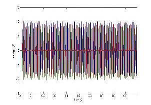
Fig 6 Input current 10A
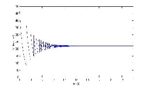
Fig 8 IBC controlled Output 220V DC
IJSER © 2011 http://www.ijser.org
International Journal of Scientific & Engineering Research Volume 2, Issue 4, April-2011 5
ISSN 2229-5518
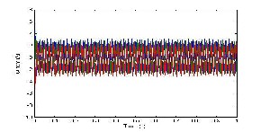
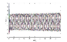
Fig 9 Output Voltage with IBC 220V AC
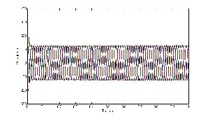
Fig 11 Output Voltage without IBC 120V
Fig 10 Output current 3A (IBC)
Fig 12 THD for input voltage 160V AC
Fig 13 THD for output Voltage 220V AC
The input voltage and current generated at the wind induction generator is shown in fig 5 & 6. The generated voltage will vary for different wind speed. The generated voltage is noted for different wind velocity and at each voltage level the output voltage is noted. The examined result shows that the output voltage is maintained at 220V even when the generated voltage is below the desired voltage level. The simulated result shown here is for generated voltage of 160V and current 9A. The generated voltage is converted to DC 160V by the rectifier, shown in fig 7. This DC voltage is boosted in the closed loop circuit with the IBC (Interleaved Boost Converted) to 220V DC,
shown in fig 8. The boosted voltage is converted to Three phase AC with the inverter and the voltage obtained is the required output voltage level of 220V and the current is 3A, shown in fig
9 & 10. The output without IBC is shown in fig 11, the obtained voltage will be same the voltage generated at input. The THD value is calculated for the input voltage and the output voltage. The graph shows that the THD has decreased compared to the input voltage, shows in fig 12 & 13.
5 CONCLUSION
Thus from the above simulated results we can conclude at that even at low wind speed and low power generation the required voltage can be obtained at the output. The main advantage of the system is that the minimum required wind speed for the power generation can be reduced and generator power ratings can be reduced. The gear mechanism between the turbine and the shaft can be reduced. The displayed out is taken when the wind speed is 7m/s. At this speed the generator generates 160V AC and this voltage is boosted in the IBC to 220V DC which is the required voltage level. Steady-state results under various loads show that the designed control system for IG can maintain at desired levels. The simulated results of output voltage validate the required performance of the proposed control scheme. Thus the voltage obtained at the output is regulated with the IBC and inverter block.
IJSER © 2011 http ://www.ijser.org
International Journal of Scientific & Engineering Research Volume 2, Issue 4, April-2011 6
ISSN 2229-5518
REFERENCES
[1] E.D. Basset and F.M. Potter, “Capacitive excitation of induction generators,” Trans. American Institute Electrical Engineering, vol.
54, pp. 540-545, 1935.
[2] J. Arrilaga and D.B. Watson, “Static power conversion from self- excited induction generators,” IEE Proceedings, vol. 125, no. 8, pp.
743-746, 1978.
[3] R. Ramakumar, “Renewable energy sources and developing countries,” IEEE Trans. Power Apparatus and Systems, vol. 102, no.
2, pp. 502-510, 1983
[4] S.S. Murthy, O.P. Malik, and A.K. Tandon, “Analysis of self excited induction generators,” IEE Proceedings, Part C— Generation, Transmission, and Distribution, vol. 129, no. 6, pp. 260-
265, 1982.
[5] B. Singh and L.B. Shilpakar, “Analysis of a novel solid state voltage regulator for a self-excited induction generators,” IEE Proceedings, Generation Transmission and Distribution, vol. 145, no.
6, pp. 647-655, 1998.
[6] E.G. Marra and J.A. Pomilio, “Induction-generator-based system providing regulated voltage with constant frequency,” IEEE Trans. Industrial Electronics, vol. 47, no. 4, pp. 908-914, 2000.
[7] E.G. Marra and J.A. Pomilio, “Self-excited induction generator controlled by a VS-PWM bidirectional converter for rural applications,” IEEE Trans. Industry Applications, vol. 35, no. 4, pp.
877-883, 1999.
[8] S. Wekhande and V. Agarwal, “Simple control for a wind-driven induction generator,” IEEE Industry Applications Magazine, vol. 7, no. 2, pp. 45-53, 1999.
[9] C. M.Wang, “A new single-phase ZCS-PWM boost rectifier with high power factor and low conduction losses,” IEEE Trans. Ind. Electron., vol. 53, no. 2, pp. 500–510, Apr. 2006.
[10] Y. Jang, D. L. Dillman, and M. M. Jovanovic´, “A new soft- switched PFC boost rectifier with integrated flyback converter for stand-by power,” IEEE Trans. Power Electron., vol. 21, no. 1, pp.
66–72 , Jan. 2006.
[11] Y. Jang, M. M. Jovanovic´, K. H. Fang, and Y. M. Chang, “High- powerfactor soft-switched boost converter,” IEEE Trans. Power Electron., vol. 21, no. 1, pp. 98–104, Jan. 2006.
[12] K. P. Louganski and J. S. Lai, “Current phase lead compensation in single-phase PFC boost converters with a reduced switching frequency to line frequency ratio,” IEEE Trans. Power Electron., vol. 22 , no. 1, pp. 113–119, Jan. 2007.
[13] K. Kobayashi, H. Matsuo, and Y. Sekine, “Novel solar-cell power
supply system using a multiple-input DC–DC converter,” IEEE Trans. Ind. Electron., vol. 53, no. 1, pp. 281–286, Feb. 2006.
[14] S. K. Mazumder , R. K. Burra, and K. Acharya, “A ripple- mitigating and energy-efficient fuel cell power-conditioning system,” IEEE Trans. Power Electron. , vol. 22, no. 4, pp. 1437–1452, Jul. 2007.
[15] G. Yao, A. Chen, and X. He, “Soft switching circuit for
interleaved boost converters,” IEEE Trans. Power Electron., vol. 22, no. 1, pp. 80–86, Jan. 2007.
[16] Q. Ting and B. Lehman, “ Dual interleaved active-clamp forward with automatic charge balance regulation for high input voltage
application ,” IEEE Trans. Power Electron., vol. 23, no. 1, pp. 38–44,
Jan. 2008.
[17] W. Li and X. He, “ZVT interleaved boost converters for high-effi- ciency, high step-up DC–DC conversion,” IET Electron. Power Appl.,vol. 1, no. 2, pp. 284–290, Mar. 2007.
[18] W. Li and X. He, “An interleaved winding-coupled boost converter with passive lossless clamp circuits,” IEEE Trans. Power Electron., vol. 22, no. 4, pp. 1499–1507, Jul. 2007.
BIOGRAPHIES
N.Prasanna Raj, from Chennai, finished his UG in Coi mbatore Institute of Engineering and Information Technology and pursuing his final year M.E. in Power Electronics and Drive s in Kumaraguru College of Technology, Coimbatore. (prraj.n@gmail.com)
M.Mohanraj, from Erode, finished his UG in Bharathiar University and he obtained PG in Power System Engineering in Annamalai University and he is currently working as Assistant Professor in EEE depart ment, Kumaraguru College of Technology, Coi mbatore and a Life member of ISTE. His research area includes Wind Energy Conversion, Solar Energy, Machines and Power Quality Issue s.(mmrguru@gmail.com)
Rani Thottungal, obtained her B.E and M.E degrees from Andhra University and Doctorate from Bharathiar University. She is currently working as Professor and Head in EEE department, Kumaraguru College of Technology, Coimbatore. Her research interest includes Power System, Power Inverter and Power Quality Issues.
IJSER © 2011 http://www.ijser.org