Figure 1: Geometrical structure of proposed antenna
International Journal of Scientific & Engineering Research, Volume 4, Issue 8, June 2013
ISSN 2229-5518
1749
Design of a High Gain Microstrip Patch Antenna for WLAN/Bluetooth Application at 2450 MHz
Frequency
Md. Abu Baker Siddique Akhanda, Ibnul Sanjid Iqbal, Shaon Md. Foorkanul Islam
Abstract— This paper presents the design and analysis of a small size, low profile, inexpensive and high gain microstrip patch antenna. The new designed antenna has operating frequency of 2.45 GHz which is useful in WLAN or Bluetooth applications. This antenna is directly feed by 50Ω coaxial connector. The suggested model is simulated and various antenna parameters such as radiation pattern, standing wave ratio (SWR), Impedance of the antenna model are analyzed using Numerical Electromagnetic Code (4NEC2) software package. The proposed antenna shows high peak gain of about 9.79 dBi and return loss is about -27.318 dB.
Index Terms— Microstrip patch antenna, SWR, Return Loss, Rediation Pattern, Gain, Bandwidth, WLAN and Bluetooth.
—————————— ——————————
n wireless communication system, antenna is one of the most significant part. So, the design of antenna has become more important in communication sector. There are various types of antenna used in communication system sych as dish antenna, patch antenna, slot antenna, folded dipole antenna etc. which are used to transmit and receive signal or data.
Each type of antenna has its own properties and usage.
Microstrip patch antennas are popular for their perfor-
mance, their robust design, fabrication and their extent usage.
Microstrip patch antenna can be flushmounted to material or
other existing surfaces and it only requires space for the feed
line which is normally placed behind the ground [1]. It uses
conductive strips or patch formed on the surface and is sepa- rated by a thin dielectric substrate from the ground. A patch is
typically wider than a strip and its shape and dimensions are important features of the antenna [2]. The shapes of conduct- ing patch are of various types such as square, rectangular, cir- cular, elliptical, triangular or any other desired configuration. The patch is generally made of conducting material such as copper or gold. The radiating patch and the feed lines are usu- ally photo etched on the dielectric substrate [3]. There are two methods of feeding. These are contacting and non-contacting method. In the contacting method, the RF power is fed directly to the radiating patch using a connecting element such as a microstrip line or probe feed. In the non-contacting scheme, electromagnetic field coupling is done to transfer power be- tween the microstrip line and the radiating patch. This in- cludes proximity feeding and aperture feeding [4]. Most
————————————————
Md. Abu Baker Siddique Akhanda, BSc program in Electronics and Communication Engineering,Khulna University of engineering and Tech- nology, Bangladesh, PH-+8801677039345,E-mail:Shumel0809@ymail.com
Ibnul Sanjid Iqbal, BSc program in Electronics and Communication Engineering,Khulna University of engineering and Technology, Bangla- desh, PH-+8801825083969. E-mail: Ibnul_sanjid@yahoo.com
Shaon Md. Foorkanul Islam, BSc program in Electronics and Communi- cation Engineering, Khulna University of engineering and Technology, Bangladesh, PH-+8801716595289, E-mail: Shaon_ece_kuet@yahoo.com
commonly used feeding techniques are: Microatrip line feed- ing and Coaxial cable or probe feeding [5]. Microstrip patch antenna has many advantages such as low profile, low cost, light weight, small size, easy to analysis and fabrication and capable of dual or triple frequency operation. Because of these advantages, microstrip patch antenna becomes popular in mobile and satellite communication system, global positioning system (GPS), radio frequency identification (RFID), WiMax, radar application, rectenna application, telemedicine and me- dicinal application. Rectenna is a rectifying antenna that is used to directly convert microwave energy into DC power. Besides of these advantages, microstrip patch antenna has some disadvantages too. The major disadvantages of this an- tenna are low efficiency, low gain and very narrow frequency bandwidth which is typically only a fraction of a percent or at the most a few percent [6].
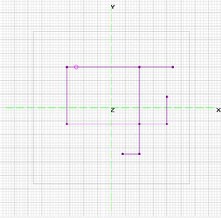
The design of the proposed antenna is shown in figure 1.
Figure 1: Geometrical structure of proposed antenna
IJSER © 2013
International Journal of Scientific & Engineering Research Volume 4, Issue 8, June-2013
ISSN 2229-5518
1750

Figure 2: 3D view of the proposed antenna
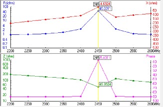
The impedance should match with the feeding line impedance which is 50 Ω in figure 5, it is 49.85.
Reflection coefficient or return loss is defined as the ratio of
Figure 5: Input Impedance
reflected power to the incident power. For practical antenna its value should be less than -9.54 db. Simulated return loss in case of designed triangular microstrip antenna is – 26.5 db at resonant frequency 2.45 GHz as shown in figure 3 and figure
4. Voltage standing wave ratio should have the value less than
2 for the antenna to radiate. In case of designed rectangular microstrip antenna it comes out to be 1.009 as shown in figure
3 and figure 4.
Figure 3: SWR versus frequency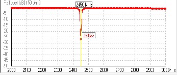
Figure 4: Reflection coefficient versus frequency
The total gain curve is shown in figure 6 which is 9.79. This gain is very high for a patch antenna.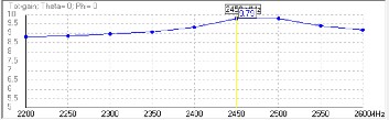
Figure 6: Total Gain
It is found, in practice that radiated energy from antenna is not of same strength in all directions. Instead it is more in one di- rection less or zero in other direction. The radiated energy in a particular direction is measured in terms of field strength at a point which at particular distance from the antenna. Radiation pattern is a graph which shows the variation of actual field strength of electromagnetic field at all points which are at equal distance from antenna. Practical antennas are designed to have directional radiation pattern, i.e. they will radiate or receive radiation more effectively in one specified direction.
IJSER © 2013
International Journal of Scientific & Engineering Research Volume 4, Issue 8, June-2013
ISSN 2229-5518
1751
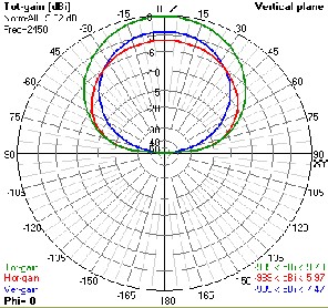
Figure 7: Radiation Pattern
Figure 8: Pictorial view of the practically designed antenna
In this paper a new high gain antenna design has been pre- sented which looks like a rectangular with 3 single elements connected with it, 2 of those are ‘L’ shaped and the last one is a ‘I’ shaped. This micro strip antenna for enhancing gain and bandwidth has been designed, simulated and analyzed theo- retically and practically shown in fig 8. Simulation results of a high gain micro strip patch antenna at 2.45GHz frequency have been presented.
This antenna has wide range of applications in the field of wireless communication such as WLAN or Bluetooth. Due to its small size and less weight these type of antenna are fre- quently used in plane, satellite and spacecraft. Due to its high gain it can be used very effectively on point to point commu- nication.
Our future target is to miniaturization of the proposed anten- na with multiband and increasing operating bandwidth for different communication system.
The authors wish to thank Prof. Dr. Md. Mostafizur Rahman and Asst. Prof. Mr. Khaled Mahbub Morshed, Khulna University of Engineering and Technology, for their senciour advice and support in the work. Authors also thank to their parents and some friends for providing such support during the work.
[1] K.D.Parsad, Antenna and Wave Propagation, Satya Parkashan, 2005.
[2] Rajeshwar Lal Dua, Himanshu Singh, Neha Gambhir, "2.45 GHz Microstrip Patch Antenna with Defected Ground Structure for Blue- tooth", IJSCE, Volume-1, Issue-6, January 2012.
[3] C. A. Balanis, Antenna Theory, John Wiley & Sons, Inc., 1997.
[4] Ramesh G, Prakash B, Inder B, and Ittipiboon A. (2001) Microstrip antenna design handbook, Artech House.
[5] Gurdeep Singh, Jaget Singh, "Comparative Analysis of Microstrip
Patch Antenna With Different Feeding Techniques" International Conference on Recent Advances and Future Trends in Information Tech- nology (iRAFIT) Proceedings published in International Journal of Com- puter Applications® (IJCA), 2012.
[6] Indrasen Singh, Dr. V.S. Tripathi,"Micro strip Patch Antenna and its
Applications: a Survey" IJCTA, Vol 2 (5), SEPT-OCT 2011.
IJSER © 2013