International Journal of Scientific & Engineering Research, Volume 6, Issue 2, February-2015 704
ISSN 2229-5518
Design of a Fingerprint Reader Enabled Remote
Monitoring Module with Interface to Web
Applications
Nathan David1*, Patrick Ocheja2, Paschal Udeh2, Olisa Okpoko2
1Lecturer and Project Supervisor, Department of Electronic Engineering, Faculty of Engineering, University of Nigeria, Nsukka.
2Final Year (2014), Undergraduate Project, Department of Electronic Engineering, Faculty of Engineering, University of
Nigeria, Nsukka.
*Corresponding author
Nathan David
Email: nathan.david@unn.edu.ng
Abstract: Engineering has continued to redefine the way we live and carry out processes. In the light of monitoring, control and consequently automation through to information management, technologies continue to emerge. This work presents a custom designed fingerprint monitoring module with interface to web applications for remote monitoring. Core design and implementation were realized through the use of ATmega2560 installed on an Arduino mega development board. For wireless data transmission, Zig-Bee wireless technology was used to provide connection between the module and a server which then synchronizes its data with all other connected devices. By way of testing, a lecture attendance monitoring scenario is provided in this work. This work provides a new design for future systems and possible ways of integration to existing systems.
Keywords: monitoring, information, integration, arduino, Zig-Bee, ATmega2560, transmission, wireless, communication, design, modules, efficiency, programming, lecture attendance, system, and technology.
—————————— ——————————
INTRODUCTION
Remote monitoring of information is a very vital integration in most processes. Different technologies have been developed to enable remote monitoring. In this work, we present a novel technology that enhances remote monitoring using low cost devices. The bulk of the system was realised using Arduino mega development board and an XBee RF module (running on a Zig- Bee IEEE 802.15.4 protocol specifications). With Zig-Bee technology, power consumption, reliability and portability challenges that are faced in handling wireless communications are
recommend future designs to integrate this low cost implementation of a wireless fingerprint enabled remote monitoring module.
HARDWARE DESIGN
The hardware consists of three major components; Arduino Mega
development board driven by ATmega2560 chip, XBee RF
modules and GT-511C3 Fingerprint reader.
conveniently handled [1].
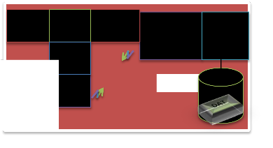
This module has two main parts; a Remote Controller unit and the Base Station as shown in figure 1. The remote controller unit houses the fingerprint reader which is installed at the entrance of where data monitoring or access restriction is required. It also has an XBee RF module which facilitates communication with the base station. Base station management software was also developed.
The base station basically, is a remote computer with an XBee RF
module which responds to communication requests from the remote controllers and other devices which could be web applications or preconfigured devices. The base station contains developed software for management of modules. This software
POWER
SUPPLY
REMOTE CONTRO LLER UNIT
CONTR
OLLER
FINGER PRINT
RF MODU
DISPLAY
block diagram
RF
MODULE (COORDINATOR)
BASE
BASE
STATION
provides interfaces configuring new modules or devices, viewing
module health (battery life and current status), data summary and synchronization of data with connected devices.
This project in its own right, defines a method for wireless monitoring of processes through provision of a fingerprint enabled module for access authentication. Consequently, we
ARDUINO MEGA
The arduino microcontroller development board is an open-source physical-computing platform that is based on a simple microcontroller board and a development environment for writing the software for the board. The Mega version shown in figure 2 is driven by an ATmega2560 microprocessor which has a 256KB
IJSER © 2015 http://www.ijser.org
International Journal of Scientific & Engineering Research, Volume 6, Issue 2, February-2015 705
ISSN 2229-5518
flash memory. With this increased memory, input-output functionalities are significantly improved compared to standard
Arduino. The Mega has also four hardware serial ports making it ideal for larger projects that may require more complex circuit realisations.
54 digital input-output pins and 16 analog input pins are provided on the board. The Arduino Mega version provides other features for interfacing with shields [2].
Arduino Mega was used in this work to interface most of the
hardware devices such as the power supply unit, XBee module and the fingerprint reader. Voltage demands of 3.2V along the fingerprint reader – arduino TX/RX line is met using the voltage divider concept as shown in figure 3 while that of the XBee module is conveniently supplied from the arduino development board. Interaction between the different devices so connected is then defined and controlled by the logic specified and
programmed onto the arduino mega ATmega2560 chip.
Figure 2 The Arduino Mega pins and layout.
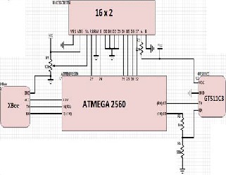
Figure 3 Circuit diagram of hardware operation
XBEE RF MODULE
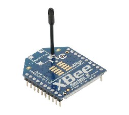
The XBee RF module is usually used for applications that require low latency and predictable communication timing. It provides quick, robust communication in point-to-point, peer-to-peer and multipoint/star configurations. XBee multipoint RF module maximizes wireless performance and ease of development whether it is deployed as a pure cable replacement for simple serial communications or as part of a more complex network of sensors. Figure 4 shows the XBee module used.
Figure 4 XBee Series 2
The transmission of data over long distances is done by passing data through intermediate devices to reach more distant ones thereby creating a mesh network. A basic feature of the Zig-Bee technology is that it has a wireless and ad hoc network; therefore, it can be used in applications where a central node cannot be relied upon. The Zig-Bee network possesses three important features which are;
Coordinator: Zig-Bee networks always have a single coordinator device. When using the Zig-Bee technology, each network must be formed by a coordinator and not more than one coordinator can exist on the same network.
Router Device: The router can perform the function of connecting existing networks, sending, receiving and routing information. Routers are always plugged into an electrical outlet because they must be turned on all the time.
End Device: End devices are stripped-down versions of a router.
They can also connect networks, send and receive information. End devices can power themselves intermittently because they do not act as messengers between any other devices. They need a router or a coordinator to be their parent device. The parent device helps the end device to connect to other networks and store messages for them when they are in sleep mode. There can be multiple end devices in a Zig-Bee network. Sometimes, the routers can be absent but the coordinator must be present because it is the most important of the three.
As one of its defining features, Zig-Bee provides facilities for
carrying out secure communications, protecting establishment and transport of cryptographic keys, cyphering frames and controlling devices. It builds on the basic security framework defined in IEEE 802.15.4. This part of the architecture relies on the correct management of symmetric keys and the correct implementation of methods and security policies. Zig-Bee is used in applications that require only a low data rate, long battery life, and secure networking. Zig-Bee has a defined rate of 250kbit/s, best suited for periodic or intermittent data or a single signal transmission from a sensor or input device.
For single instance deployment (as presented here), atleast two XBee RF modules will be required and only the one attached to the base station is configured as a coordinator while others will be end devices communicating and being managed by the coordinator. In this work, Zig-Bee technology is harnessed by the XBee RF module in the realisation of the communication of fingerprint image captured by the fingerprint reader to the base
IJSER © 2015 http://www.ijser.org
International Journal of Scientific & Engineering Research, Volume 6, Issue 2, February-2015 706
ISSN 2229-5518
station for verification or enrolment. Packets sent over the network are typically of the format shown in figure 5.
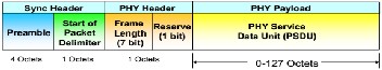
Figure 5 Zig-Bee packet structure
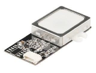
GT-511C3 FINGERPRINT READER
Biometric technologies are automated methods of verifying or recognizing the identity of a living person based on a physiological or behavioral characteristic [3]. Biometric authentication requires comparing a registered or enrolled biometric sample against a newly captured biometric sample. During enrolment, a sample of the biometric trait is captured, processed by a computer and stored for later comparison. Biometric recognition can be used in identification mode where the biometric system identifies a person from the entire enrolled population by searching the database for a match [4].
In fingerprint biometrics, there is a matching process between two fingerprints for verification. Humans have used fingerprints for personal identification for more than 100 years [5]. A fingerprint is the pattern of ridges and furrows on the surface of the fingertip. No two persons therefore have exactly the same arrangements of patterns and the pattern of every individual remain the same for life. The analysis of fingerprints for matching purposes generally requires the comparison of several features of the print pattern. These include patterns that are aggregate characteristics of ridges and minutia points which are the unique features found within the pattern [6]. The three basic patterns of fingerprint ridges are the arch, the loop and the whorl. Scientists have discovered that family members often share the same general fingerprint pattern which leads to the belief that these patterns are inherited [7]. Minutia features of fingerprint ridges are; ridge ending, bifurcation and the short ridge.
The finger scan technology makes use of the unique fingerprint
pattern that is present on the human finger to identify or verify the identity of an individual. Although the system has numerous advantages, the finger-scan technology has some weaknesses that prevent it from being useful in certain applications. It has been discovered that most devices are unable to enrol some small percentage of users [8]. This is attributed to hardware limitations as well as physiological reasons for special population groups. The performance of finger scan technology also deteriorates over time. This is because fingerprints can change due to aging, wear or tear. A snap short of the fingerprint scanner used in this work is shown in figure 6.
Figure 6. Fingerprint reader (GT-511C3)
The two processes the fingerprint reader was used to achieve are enrolment and verification. Figure 7 shows the block diagram of the paths taken by the processes. The hardware design also involves provision for power management and maintenance of installed devices as the fingerprint reader for instance was observed to get hot if left on and unused for a long time. To take care of this, a button is provided to turn off the device and also turn on as required. Typically it takes a few seconds to boot up so little or almost no delay is experienced. Also during every communication between a remote controller unit and the base station, the battery level is sent to the base station for management.
Figure 7 Biometric system processes.
SOFTWARE DESIGN
The software design was achieved using two programming languages; Java programming language and arduino adapted Processing programming language. The flowchart for the system is shown in figure 9. Java programming language was used to develop the software resident on the base station that manages all remote controller modules. The arduino adapted Processing language was used in the programming of the arduino mega development board.
IJSER © 2015 http://www.ijser.org
International Journal of Scientific & Engineering Research, Volume 6, Issue 2, February-2015 707
ISSN 2229-5518
The software resident on the base station provide features which include users enrolment, modules registration, module health
monitoring and for this use case of lecture attendance monitoring; view on-going lectures for the day. Backend definitions include XBee packets reception and transmission, frame formatting, thread management; enrolment and verification.

The logics programmed on the arduino mega drive the hardware devices to realise the two basic functions of enrolment and verification. For both processes, the fingerprint image is read and its byte equivalent is well formed into a packet for onward transmission to the base station. The payload which has a maximum size of 48bytes is delimited with ever distinct information having a predefined size. The packet/frame format of Zig-Bee technology as defined by the IEEE802.15.4 standard is shown in figure 6 while the payload and distinct information size delimiting is shown in figure 8.
MESSAGE TYPE (6BYTES) | BATTERY LEVEL (6BYTES) | LOCATION (6BYTES) | MESSAGE (30BYTES OR LESS - PADDED IF LESS) |
Figure 8 Well-formed payload with distinct contents and sizes
Interface to web applications was developed using Java Platform Enterprise Edition (JEE). JEE is Oracle’s enterprise Java computing platform. The platform provides an API and runtime environment for developing and running enterprise software including network and web services. Java EE initially evolved as an enterprise application deployment platform (Java EE 5) that
focused on robustness, web services and ease of deployment [9].
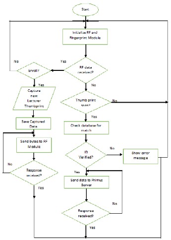
Figure 9 Software design flowchart
A modification to Java EE 5 was Java EE 6 which further streamlined the development process and increased the flexibility of the platform.
The various attributes of the base station software application are
discussed hereforth.
Enroll
The enroll interface is used when the fingerprint (biometric detail)
of a new lecturer is to be obtained. At this interface, details obtained are; name of lecturer, department, e-mail and the mobile location. The mobile location is the place where the lecturer is to take his/her lecture (fingerprint reader location). A screenshot is shown in figure 10.
IJSER © 2015 http://www.ijser.org
International Journal of Scientific & Engineering Research, Volume 6, Issue 2, February-2015 708
ISSN 2229-5518
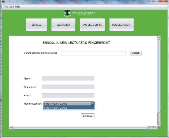
Figure 10 Enroll Interface
Lectures
The lectures interface shows the ongoin lectures during the day. The interface has fields as shown below which makes this feature
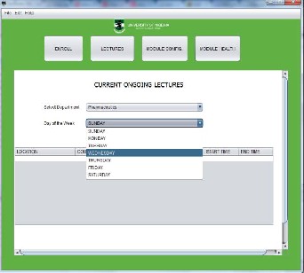
possible. A screenshot is shown in figure 11.
Figure 11 Lectures Interface
Module Configuration
The module configuration interface has the moduile version, mac
address and module address sub-module. This interface help in the installation of a new biometric module in a classroom. A snippet of some part of the code used in achieving this is shown in figure 12.
Figure 12: Module Configuration Interface
Module Health
The module health shows the battery level of the module and the
location of the module. It also has a column that shows the last time a module communicated successfully. Figure 13 shows a snippet of code that forms the packet containing the battery level.
Figure 13 Packet transmission logic on the arduino mega2560
CONCLUSION
Remote information monitoring can be achieved using this
custom made monitoring module. It enhances remote access by provision of interface for communicating with web applications over the internet. Processes such as lecture attendance monitoring, examinations check-in, conference participants admittance and others are areas this solution can be deployed. With the use of the
IJSER © 2015 http://www.ijser.org
International Journal of Scientific & Engineering Research, Volume 6, Issue 2, February-2015 709
ISSN 2229-5518
Zig-Bee technology, fast communication was achieved. However, a low coverage as inherent in the XBee RF module used is still a
challenge. For every deployment, the module must be within the reach of the base station. Future work will focus on enhancing coverage.
REFERENCES
[1] | R. C. Dorf, "Broadcasting and Optical Communication Technology," CRC Press 2006. page 5-5. |
[2] | M. Evans, J. Noble, J. Hochenbaum, "Arduino in Action," Manning Publications 2013. page 7. |
[3] | D. M. James Wayman. Anil Jain, "An Introduction to Biometric Authentication Systems," 2014. |
[4] | Nathan David, Patrick Ocheja, Paschal Udeh, Olisa Okpoko "Design of a University portal with Biometric Lecture Attendavce Monitoring System", SJET 2014; 2(6B) |
[5] | Microsoft, "Biometrics," Encarta, 2009. |
[6] | Prabhakar, "Pattern recognition letters," Combining multiple matches for a high security fingerprint verification system, vol. 20, 1999. |
[7] | ANSI/NIST, "Data format for the interchanging of fingerprint information," American National Standards Institute, America, 1993. |
[8] | S. Nanavati, "Biometrics: Identity Verification in a Networked World," Wiley Computer Publishing, New York, 2002. |
[9] | "Introduction to Java Platform, Enterprise Edition 7," An Oracle White paper, pp. 3-16, June 2013. |
IJSER © 2015 http://www.ijser.org