International Journal of Scientific & Engineering Research, Volume 4, Issue 7, July-2013 2298
ISSN 2229-5518
Faizan Ahmad & Naseem Ahmad khan
Abstract- The aim of this work is to develop a program in C++ software for the design of triple effect evaporator in forward feed mode with mechanical design. In this mechanical design a short tube vertical evaporator (STV), Calandria type has been used .The developed programme is then used for solving the non-linear equations for the evaporation system and the results obtained are finally compared with the problem given in Kern [1], Foust [2], and Dutta [3]. Evaporation ordinarily means vaporization of a liquid or that of a solvent from a solution. But in chemical engineering terminology, evaporation means removal of a part of the solvent from a solution of a non- volatile solute by vaporization. W here the objective of vaporization is to concentrate the solution. It is one of the most important operations in the process industries. Typical examples are concentration of sugar-cane juice in a sugar plant, concentration of an aqueous solution of ammonium sulphate in a fertilizer plant, concentration of dilute recycled sodium hydroxide in an alumina plant and many others. Evaporation differs from drying and distillation. In distillation the components of a solution are separated depending upon their distribution between vapour and liquid phases based on the difference of relative volatility of the substances. Whereas the removal of moisture from a substance in presence of a hot-gas stream to carry away the moisture leaving a solid residue as the product is generally called drying. Evaporation is normally stopped before the solute starts to precipitate in the operation of an evaporator.
Index Terms- Process Design, Triple effect evaporator, Mechanical Design, Forward feed.
———————————————————
EVAPORATORS are generally used in chemical industry for concentrating chemical solutions by vaporising off the water content of the solution. Concentration of the liquor is required for the crystallization of the desired material from the solution such as in the production of sugar crystals from sugar cane juice or in the manufacturing of caustic soda, table salt etc., or for the removal of dissolved salt prior to recovery of a valuable product such as in desalting of spent soap lye prior to glycerol recovery. Evaporators mostly used in the process industry have tubular heating surfaces. An adequate number of tubes are provided through with the solution circulates. Tubes are heated by steam that condenses on the outer surface. The velocity of circulation of the solution through the tubes should be reasonably high. The overall economy of the system is best improved if evaporators are operated in multiple effects. Multiple effect evaporators can be operated with forward feed, backward feed, or mixed feed. The feed is called forward if it is fed to the effect in series in the same order as the steam flows. Under these conditions, it is not necessary to pump the liquor between effects, so the liquor flows by itself from one effect to another and the only pump required will be the discharge pump at the last effect. This type of feeding is best suitable![]()
When the feed liquor is at or above the saturation temperature of the first effect and as a result flash evaporation occurs in the first effect and continues to occur in the subsequent effects since they are at lower pressure. The concept of evaporator body was first introduced by an African-American engineer Norbert Rillieux in 1845. However, the mathematical modeling for its design started in 1928 with the work of Badger. Since then, many Investigators have proposed mathematical models for evaporators. Design of multiple effect evaporators has received considerable attention over the last 30 years and several key contributions have appeared in the literature. Simpson et al. (2008) proposed a new economic evaluation procedure to optimize the design and operation of multiple effect evaporators and compared it with the traditional chemical engineering approach of total cost minimization.
A short tube vertical evaporator is used for mechanical design. This is one of the oldest but widely used insugar industry in evaporation of sugar-cane juice. These are also known as Calandria or Robert evaporator. Short-tube vertical evaporators consists of a short tube bundle (about
4 to 10 ft. in length) enclosed in a cylindrical shell. This is
called calandria. An evaporator of this type is shown in Figure 1.The feed is introduced above the upper tube sheet and steam is introduced to the shell or steam chest of the calandria. The solution is heated and partly vaporized in the tubes. The diameter of a STV evaporator ranges from one meter to a few meters. Tubes of 50 mm to 76 mm (2 to
3 inches) diameter and 1.2 to 2 m length are commonly
used. The cross-sectional area of the downtake is liberally
IJSER © 2013 http://www.ijser.org
International Journal of Scientific & Engineering Research, Volume 4, Issue 7, July-2013 2299
ISSN 2229-5518
sized and generally varies from 50% to 100% of the flow area of the tubes. This ensures low frictional resistance to flow through the downtake. Several advantages of (STV) evaporator have been reported in the literature i.e. it has high heat-transfer coefficients at higher temperature differences, low headroom, easy mechanical descaling and is relatively inexpensive, that is why STV evaporator has been preferred for mechanical design.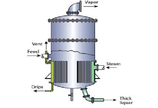
Fig.1 Calandria Type Evaporator
3 VARIOUSASSUMPTIONS USED
The final concentration in the liquid leaving the last effect in forward feeding.
Physical properties such as heat capacities of the
liquid and vapours.
Over all heat transfer coefficient in each effect.
In the formation of this programme forward feeding
arrangement are considered with one type of condition given i.e. heat capacity and the following steps that are taken in calculation of triple effect evaporator are as follows
From the known outlet concentration and
pressure in the last effect, the boiling point in the last effect can be determined. (If a BPR is present, this can be determined from a Duhring line plot.)
Determine the total amount of vapour
evaporated by an overall material balance. Make a total material balance on effects I, II and III to obtain P1, P2, andP3.
Estimate the temperature drops ∆t1, ∆t 2 and
∆t3
Calculate the values of heat transferred in
each effect. For each effect calculate the areas
A1 , A2 and A3 and then calculate the average value of A
In designing this new system the following assumptions
by A =
A1 +
![]()
A2 + A3
3
are being made:
The boiling point rise is negligible.
Specific heat of feed is constant for all
temperatures and concentrations.
Overall heat transfer coefficient remains constant
throughout the operation of the evaporator.
Evaporator is operated at steady state.
Vapours from each effect are solute free.
Forward feed arrangement is employed.
Heat transfer area is nearly equal for each effect.
In doing calculations for a triple effect evaporator system, the values to be obtained are usually the area of the heating surface in each effect, the Kg of steam per hour to be supplied, and the amount of vapour leaving each effect, especially in first effect. The given or known values are as follows.
Calculate the overall steam economy and steam economy in each effect.
After taking the assumptions, apply the material balance
over each effect.
Specification- F, xF , xp3, t1, t2, t3, cf, c1, c2, c3, U1, U2 , U3, To Find- P1, P2, P3, E, E1, E2, E3, A1, A2, A3, S, ES, EC Material balance on the whole system
F = E + P3 (1)
Component Balance on the whole system is
F*xf = P3 *xp3 (2)
P3 = (F*xF )/xP3 (3)
The distribution of ∆t can be as followed
∆t1 = ts1 – tL1 (4)
∆t2 = ts2 – tL2 (5)
∆t3 = ts3 – tL3 (6)
Steam pressure to the first effect.
Final pressure in vapour space of the last effect.
Feed condition and flow to the first effect.
Total evaporation rate
E = E1 + E2 + E3 (7)
Material balance on first effect
F = E1 + P1
Or P1 = F – E1 (8)
IJSER © 2013 http://www.ijser.org
International Journal of Scientific & Engineering Research, Volume 4, Issue 7, July-2013 2300
ISSN 2229-5518
P1 = F – (E – E2 – E3 )
Material balance on Second effect
P1 = E2 + P2
P2 = P1 – E2 (9) Or P2 = F – (E – E3 )
First effect
S*λs + F*cf (t f – t1 ) = E1 *λ1 (10)
Second effect
E1 *λ1 + (F – E1 ) c1 (t1– t2 ) = E2 *λ2 (11)
Third effect
E2 *λ2 + (F – E1 – E2 ) c2 (t2 –t3) = E3 *λ3
(12)
After solving equation (7) and (12) we get
E1 = (a1 -a2 ) / (a3 -a4 ); (13)
Where values of a1, a2, a3, a4 are as follows
a1 = Eλ2 λ3 – Fλ2 c2 (t2 – t3 )
a2 = Fc1 (t1 – t2 )*(λ2 – c2 (t2 – t3 ) + λ3 )
a3 = [λ1 – c1 (t1 – t2 )]*[λ2 – c2 (t2 – t3 ) + λ3 ]
a4 = λ2 [c2 (t2 – t3 ) + λ3 ]
The value of E2 can be obtained from Equation (6)
E1λ1 + ( F − E1)c1(t1 − t 2 )
![]()
2 (14)
2
The value of E2 , P1 , P2 , and P3 can be calculated from
Equation (7), (8), (9) and Equation (1)
The value of steam consumption is given by
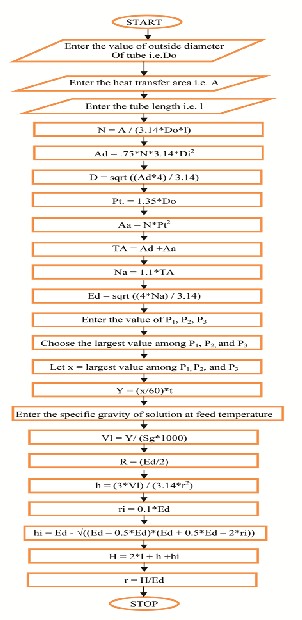
Evaporators are designed on the basis of the highest
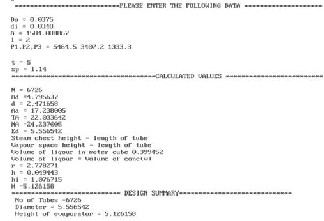
heating area. Let us select 50 mm outer diameter and 40 mm internal diameter tubes each of 2m arranged on 75 mm square pitch. For a mechanical design of triple effect evaporator a Flow chart is developed including number of tubes in the chest, Height and Diameter of evaporator. The figure illustrates it.
E 1λ 1 − FcF (tF − t 1)
![]()
S =
λ 1
(15)
The surface requirement will be
S λ 1
(16)
A1 =
A2 =
![]()
U 1∆t 1
E 1λ 2
![]()
U 2 ∆t 2
E 2 λ 3
(17)
A3 =
![]()
U 3 ∆t 3
(18)
The overall steam economy can be given by![]()
ES = E S
(19)
Steam economy in first effect
E1
(20)![]()
EC 1 =
S
Steam economy in second effect![]()
EC = E 2 (21)
E1
Steam economy in third effect![]()
EC = E 3 (22)
E 2
By using the above mentioned equations a programme is
developed for forward feed arrangement and then it is
validated by a problem given in Kern [1] on page no 412.
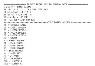
The results obtained by solving the problem given in Kern [1] on page no 412 by a developed program in C++ for process design and mechanical design is given below.
IJSER © 2013 http://www.ijser.org
International Journal of Scientific & Engineering Research, Volume 4, Issue 7, July-2013 2301
ISSN 2229-5518
F Feed rate in Kg/hr.
xF Concentration of solute in feed
xP3 Concentration of solute in product from first effect
E Total Evaporation Rate Kg/hr.
E1, E2, E3 Evaporation rate from I, II and III effect respectively in Kg/hr.
This software has been successfully applied for solving the non-linear equations for the Evaporation system. The results thus obtained are compared with the problem given in Kern [1] and satisfactory results have been achieved.
Thus it is concluded that the developed program for the design of triple effect evaporator in Forward Feed with Mechanical design can be used in many chemical and process industries. The programme is used for solving different problems and satisfactory results have been achieved.
This work was supported by Aligarh Muslim University, Aligarh (UP) – India, 202002. I am grateful to Mr Naseem Ahmad Khan, Assistant professor, Department of Chemical Engineering, AMU, Aligarh for his support and valuable guidance. I am equally thankful to Miss Fatimah Javed for her timely assistance and encouragement.
P1, P2, P3 Concentration liquid in Kg/hr.
λ1, λ2, λ3 Latent heat of steam in I, II, and III effect
Kcal/ Kg
tL1 , tL2, tL3 Temperatures of liquor in I, II, and III
effect in degree Celsius
tS1, tS2, tS3 Temperatures of steam in I, II, and III
effect in degree Celsius
C1, C2, C3 Heat capacity in I, II and III effect
Kcal/Kg 0C
CF Heat capacity of feed in Kcal/Kg 0C
A1, A2, A3 Area of I II and III effect evaporator in m2
U1, U2, U3 Overall heat transfer coefficient in I, II
and III effect in Kcal/ hr. m20C
S Total steam rate in Kg / hr. ES overall steam economy
EC1, EC2, EC3 steam economy in I, II and III effects
Do Outside diameter of tube in m l tube length in m
N Number of tubes in the chest
Ad Downtake area in m2
D Diameter of downtake in m
Pt tube pitch
Aa Annular area in m2
TA Total area in m2
Ed Evaporator diameter in m
IJSER © 2013 http://www.ijser.org
International Journal of Scientific & Engineering Research, Volume 4, Issue 7, July-2013 2302
ISSN 2229-5518
Sg Specific gravity
H Height of evaporator.
[1] Kern, D.Q., “Process Heat Transfer”, McGraw-Hill Book
Company, New York (1950).
[2] Foust, Alan S., Leonard A. Wenzel, Curtis W.Clump, Louis Maus and L.Bryce Anderson, “Principles of unit operation”, John Wiley & Sons, Singapore (1994)
[3] Dutta, B.K., “Heat Transfer Principles and Application”, Prentice
Hall of India, New Delhi (2001)
[4] Roy, G.K., “Solved Examples in Chemical Engineering”, Khanna
Publishers, New Delhi (1986).
[5] Joshi, M.V., and V.V. Mahajani, “Process Equipment Design”, Macmillan India Ltd, (1976).
[6] Balagurusamy, E., “Object Oriented Programming with C++”, 5th
Edition, Tata McGraw Hill Education Private Limited, New Delhi.
[7] Perry, J.H., “The Chemical Engineer’s Handbook”, McGraw-Hill
Book Company, New York (1934).
IJSER © 2013 http://www.ijser.org