Inte rnatio nal Jo urnal o f Sc ie ntific & Eng inee ring Re se arc h, Vo lume 3, Issue 1, January -2012 1
ISS N 2229-5518
Design of Shunt Active Power Filter to eliminate the harmonic cur- rents and to compensate the reactive power under distorted and/or imbalanced source voltages in steady state
Sangu Ravindra , Dr.V.C.Veera Reddy, Dr.S.Sivanagaraju, Devineni Gireesh Kumar
Abs tract— The shunt active pow er f ilter has proved to be a usef ul device to eliminate harmonic currents and to compensate reactive pow er f or linear/nonlinear loads. This paper presents a novel approach to determine ref erence compensation currents of the th ree-phase shunt active pow er f ilter (APF) under distorted and/or imbalanced source voltages in steady state. The proposed approach is c ompared w ith three review ed shunt APF ref erence compensation strategies. Results obtained by simulations w ith Matlab and S imulink show that the proposed approach is more eff ective than the review ed approaches on compensating reactive pow er and harmonic/neutral currents of the load, even if the source voltages are severely distorted and imbalanced. In addition, the proposed ap proach yields a simpler design of the shunt APF controller.
Inde x Terms— Shunt active pow er f ilter, Voltage source converters, Linear and nonlinear loads, PI Controllers.
—————————— ——————————
1 INTRODUCT ION
HE use of shunt active power filters (APF) to eliminate harmonic curr ents and to compensate r eactive pow er for linear /nonlinear loads has attracted much attention since the late 1970s Fig. 1 shows the schematic diagram of a thr ee-phase four-wir e shunt APF, wher e the APF senses the sour ce volta g- es and load curr ents to determine the desir ed compensation curr ents. Akagi pr oposed the instantaneous r eactive power theory (i.e.,p-q theory) for calculating the r efer ence compensa- tion curr ents r equir ed to inj ect into the networ k at the con- nected point of the nonlinear load. Since then, the theory has inspir ed many wor ks dealing w ith active pow er filter compen- sation strategies One of the peculiar featur es of a shunt APF is that it can be designed wit hout active ener gy sour ce units, such as batter ies, or in other forms in its compensation m e- chanism. In other wor ds, an ideal APF does not consume any aver age r eal power supplied by the source. To a ccomplish this function, it r equir es an effective r efer ence compensation str at- egy for both r eactive power and harmonic/neutral curr ent compensation of the load. Up to date, most r efer ence compen- sation curr ent strategies of the APF ar e determined either w ith or without r efer ence-frame transformations. For instance, the theory proposed and r equir es transformation of both sour ce voltages and load curr ents fr om the a-b-c r efer ence frame to the alpha-beta r efer ence frame to deter mine the APF r efer ence compensation curr ents in the thr ee-phase thr ee-wir e system. For applications of the APF in a thr ee-phase four-wir e system, extended the theory to handle the zer o-sequence pow er com- pensation w ith a mor e complicated contr oller design. In the author s pr oposed the gener alized instantaneous r eactive pow er theory in the r efer ence fr ame for har monic and r eactive pow er compensation.The advantages of the pr oposed a p- pr oach ar e that no r efer ence-fr ame tr ansformation is r equir ed
and a simpler APF contr oller design can be achieved.
A synchr onous r efer ence fr ame meth od for obtaining the
load curr ents at the fundamental fr equency, which will be the
desir ed sour ce curr ents. The APF r efer ence compensation cur- r ents ar e then determined by subtracting the fundamental components fr om the load curr ents. Pr oposed an algor ithm in the r efer ence frame for maintaining ideal thr ee-phase sour ce curr ents when the sour ce voltages ar e amplitude-imbalanced. In theory, the afor ementioned a ppr oaches wor k very w ell on harmonic and/or r eactive power compensation for nonlinear loads under ideal sour ce voltages. How ever, if the source vol- tages ar e imbalanced and/or distorted, the gener ated APF r ef- er ence compensation curr ents ar e discr epant and the desir ed balanced/ sinusoidal sour ce curr ents cannot be mai ntained
.Among many appr oaches for determining the APF r efer ence
compensation curr ents, one of the mainstr eams is to maintain sinusoidal source curr ents supplying aver age r eal power to the load. W ith the use of sinusoidal sour ce curr ent strategy, it is pr oved that the APF can have better per formance than other strategies .To achieve full compensation of both r eactive power
and harmonic/neutral curr ents of the load, this paper pr esents a novel appr oach to determine the shunt APF r efer ence com- pensation curr ents, even if the source voltages and load cur- r ents ar e both imbalanced and distorted. The pr oposed a p- pr oach is similar to those pr esented; it is an -r efer ence-fr ame- based method and is categor ized as a sinusoidal sour ce cur- r ent strategy. In the paper , a brief r eview of the thr ee a p- pr oaches pr oposed in fir st described. Next, the theory of the pr oposed str ategy is pr esented. The Matlab/Simulink simula- tions ar e then follow ed to compar e the usefulness of the pr o- posed method and the r eviewed appr oaches.
IJSER © 2012
http :// www.ijser.org
Inte rnatio nal Jo urnal o f Sc ie ntific & Eng inee ring Re se arc h, Vo lume 3, Issue 1, January -2012 2
ISS N 2229-5518
II. SHUNT ACTIVE POW ER FILTER
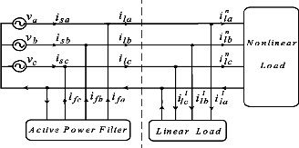
Fig.1. Schematic diagr am of thr ee phase four wir e shunt active pow er filter with linear & nonlinear loads

Active filters ar e implemented using a combination of pas- sive and active (amplifying) components, and r equir e an out- side pow er sour ce. Operational amplifiers ar e fr equently used in active filter designs. These can have high Q, and can achieve r esonance without the use of inductors. How ever , their upper fr equency limit is limited by the bandw idth of the amplifiers used. Multiple element filters ar e usually constr ucted as a lad-
line supply voltage. Since the PW M VSI is assumed to be i n- stantaneous and infinitely fast to tr ack the compensation cur- r ents, it is modeled as a curr ent amplifier with unity gain.
A. DETERMINATION OF APF REFER ENCE COMPENS A- TION CURRENTS
The pr oposed compensation strategy of the active power filter is based on the r equir ement that the sour ce curr ents need to be balanced, undistor ted, and in phase w ith the positive- sequence source voltages. The goals of the shunt APF control ar e: 1) unity sour ce pow er factor at positive-sequence funda- mental fr equency; 2) minimum aver age r eal power consumed or supplied by the APF; 3) har monic curr ent compensation; and 4) neutr al curr ent compensation. Ther efor e, the active pow er filter must pr ovide full compensation (i.e., har mon- ic/neutral curr ents and r eactive pow er ) for the nonlinear load. To achieve these goals, the desir ed thr ee-phase sour ce curr ents must be in phase w ith the positive-sequence fundamental sour ce voltage components.
der networ k. These can be seen as a continuation of the L,T
and π designs of filter s. Mor e elements ar e needed when it is
desir ed to impr ove some parameter of the filter such as stop-
ila
dc
Vdcref
Active
PI
controller
P Ilp
Iloss
band r ej ection or slope of tr ansition fr om pass-band to stop-
band.
ilb
power measurent
LPF 2 3
Ip
ilc

v va1
+
m1
v u
a1 a1
ia

Gating
va Low pass v
b filter
b1 in-phase unit
ib

Signals for
v vc1
templates
uc1
ic


i ib i
3-leg VSC
Fig: 3 Method of generating pulses to IGBTs
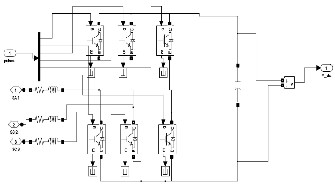
Fig.2. Cir cuit of shunt active pow er filter with IGBTs
A thr ee-phase system feeding an inverter load has been s e- lected to study the per for mance of the APF system. It has been observed that due to the non-linear character istics of pow er electr onics loads the THD’s of sour ce curr ent and terminal voltage fall well below the IEEE-519 standar d and in pr inciple APF system is used to inj ect a curr ent equal in magnitude but in phase opposition to har monic curr ent to achieve a pur ely sinusoidal curr ent wave inphase with the supply voltage. Fi g- ur e 1 shows the single-line diagr am of a simple power system with APF system ON. The heart of the APF system is the IGBT based voltage source inverter (VSI). A dc capacitor is used to deliver pow er for the VSI. For the successful operation of APF, capacitor voltage should be at least 150 % of maximum line-
III. VOLTAGE SOURCE CONVERTERS A. VSC BASED TRANSMISSION
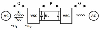
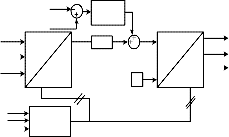
The fundamentals of VSC tr ansmission oper ation may be explained by consider ing each terminal as a voltage sour ce connected to the AC tr ans mission networ k via a thr ee-phase r eactor. The two terminals ar e inter connected by a DC link, as schemat ically shown in Fig.4
Fig: 4 Basic VSC transmission systems
IJSER © 2012
http :// www.ijser.org
Inte rnatio nal Jo urnal o f Sc ie ntific & Eng inee ring Re se arc h, Vo lume 3, Issue 1, January -2012 3
ISS N 2229-5518
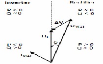
Fig: 5 shows a phasor diagram for the VSC converter con- nected to an AC networ k via a transformer inductance. The fundamental voltage on the valve side of the converter trans- former , i.e. UV(1), is pr oportional to the DC voltage as been expr essed in Eq(1).
UV(1) = kuUd ---------- (1)
The quantity ku can be contr olled by applying additional number of commutation per cycle, i.e. applying pulse w ith modulation (PW M). Using the definition of the appar ent pow- er and neglecting the r esistance of the tr ansformer r esults in
IV TW O AXIS REPRESENTATION OF 3-PHASE CURRENTS
The contr ol strategy of the active filter is based on the gen- eration of r efer ence source curr ents. These r efer ence sour ce curr ents ar e gener ated using synchronous frame r efer ence theory (SRF). The load curr ents (ila , ilb, ilc), PCC voltages (v a , vb, vc) and dc link voltage (Vdc) ar e sensed and used as feedback signals. The load curr ents in abc coordinates ar e transformed in to d-q coor dinates using Par k’s tr ansformation. The d-q components of the load curr ents ar e calculated as,
2
2
the following equations for the active and r eactive power : The
i
cos

cos
cos

ila
ld 2
3
3
active and r eactive pow er w ill in the following be defined as
i
ilb
positive if the power s flow fr om the AC networ k to the con-
lq
3 sin
sin 2
sin 2
i


lc
verter. The phase displacement angle δ will then b e positive if
3
3 ……. (2)
the converter output voltage lags behind the AC voltage in phase.
W her e cosθ and sinθ ar e obtained fr om thr ee phase PLL.

These d-axis and q-axis curr ents can be separ ated into two parts namely average and oscillator y parts as,
ild ild ild

ilq ilq ilq
…….. (3)
…….. (4)
The r efer ence sour ce curr ents in d-q coor dinates ar e trans- formed into abc coor dinates using inver se Par ks tr ansfor ma- tion and it is expr essed as,
cos
sin
i*
Fig:5 Phasor diagram of VSC and dir ection of power flows
a 2
2
2 i*
i*
cos
sin
d

b 3

3

3 i*
i*
q
B. OUTER ACTIVE AND REACTIVE POW ER AND VOL-
2
2

cos

sin
TAGE LOOP
3
3 …….. (5)
1) PW M CURRENT CONTROLLER
The r efer ence source curr ents (i*a, i* b and i*c) ar e compar ed with the sensed source curr ents (ia, ib and ic). The ON/OFF sw itching patter ns of the gate dr ive signa ls to the IGBTs ar e generated fr om the PW M curr ent contr oller. The curr ent err ors ar e computed as,
i i*
-i ; i
i* - i ; i
i* - i
. …… (6)
aerr a a
berr b b
cerr c c
These curr ent err or signals ar e fed to a carr ier less PWM curr ent contr oller for switching of the IGBTs of the VSC of the active filter.
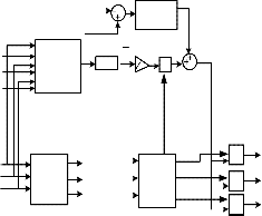
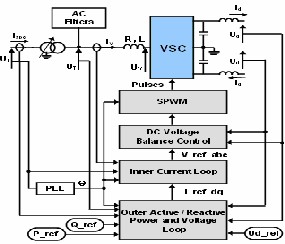
Fig: 6 Overview diagram of the VSC contr ol system
Vdc
Vdcref
ila
abc
ild
PI
controller
LPF
ild
iloss
i*
*
a
*
d-q-o b

Gating
The active power or the DC voltage is contr olled by the con- tr ol of δ and the r eactive power is contr olled by the contr ol of
ilb
ilc
v
d-q-o
d
abc
0 *
q
i*
Signals
the modulation index (m). The instantaneous r eal and imagi- nary pow er of the inverter on the valve side can be expr essed
va PLL
c
(cosθ,sinθ)


ia ib ic
in ter ms of the dq.
Fig: 7 Gating signals for PW M curr ent contr oller
IJSER © 2012
http :// www.ijser.org
Inte rnatio nal Jo urnal o f Sc ie ntific & Eng inee ring Re se arc h, Vo lume 3, Issue 1, January -2012 4
ISS N 2229-5518
2) PW M FOR POW ER BALANCES THEORY
The contr ol strategy of the active filter is based on the gen- eration of r efer ence sour ce curr ents. The r efer ence source cur- r ents ar e generated using pow er balance theory (PBT). The load curr ents (ila , ilb, ilc), PCC voltages (v a , vb, vc) and dc link voltage (Vdc) ar e sensed and used as feedback signals.
Thr ee phase voltages at the generator terminals (va, vb and vc)
ar e sensed and amplified to compute their amplitude as,
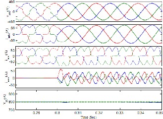
V. SIMULATION RESULTS
1. SYNCHRONOUS REFERENCE METHOD

Vt
2 v2 v2 v2
3
……. (7)
The dc bus voltage err or Vd cer at nth sampling instant is ex- pr essed as,
Vdcer ( n) Vdcref ( n) -Vdc( n)
……… (8)
W her e Vd cref is the r efer ence dc voltage and Vd c(n) is the sensed dc link voltage of the CC-VSC. The output of the PI contr oller for maintaining the dc bus voltage of the CC-VSC at the nth sampling instant is expr essed as,
The r efer ence sour ce curr ents (i*a , i*b and i*c) ar e compar ed w ith
the sensed sour ce curr ents (ia , ib and ic). The ON/OFF sw itch- ing patter ns of the gate dr ive signals to the IGBTs ar e gener at-
ed fr om the PW M curr ent contr oller. The curr ent err ors ar e computed as,
Fig: 9 System per formances with Non linear loads
i i*
- i ; i
i* - i ; i
i* - i
. …… (9)
aerr a a
berr b b
cerr c c
These curr ent err or signals ar e fed to a carr ier less PWM curr ent contr oller for switching of the IGBT of the VSC of the active filter.
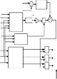
Fig:10 Pow er deliver ed by source b efor e compensation
ila
i
Vdc
Vdcref
Active power
P
LPF
PI
controller
Ilp
2
3
Iloss
lb
ilc
measurent Ip
t
Amplitude
va in-phase ua
*
a 

* Gating
v
b unit u
v templates b
uc
ib
ic
ia


ib ic

Signals for
3-leg VSC
Fig: 8 Gating signals for Carrier less PW M curr ent contr oller
Fig:11 Power deliver ed by sour ce after compensation.
IJSER © 2012
http :// www.ijser.org
Inte rnatio nal Jo urnal o f Sc ie ntific & Eng inee ring Re se arc h, Vo lume 3, Issue 1, January -2012 5

ISS N 2229-5518
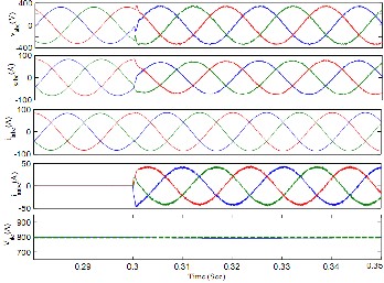
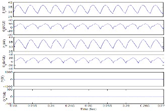
Fig:12 Linear loads w ith r equir ement of r eactive power
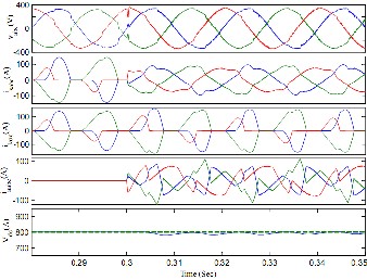
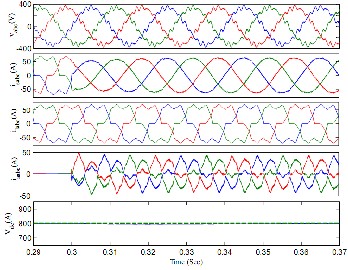
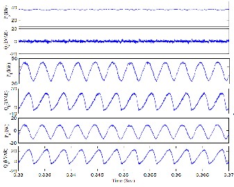
Fig: 13 Per formance of the system with unbalanced supply voltage
Fig: 14 Per formance of the system with unbalanced supply voltage using shunt active filter
IJSER © 2012
http :// www.ijser.org
Fig:15 Total Hormin distorsion in output voltage for
unbalanced supply voltages
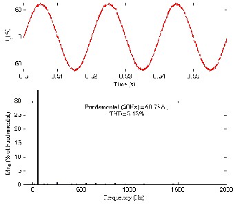
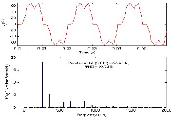
Fig:16 Total Hormin distorsion without active filter for nonlinear loads
Fig:17 Total Hormin distorsion with active filter
Inte rnatio nal Jo urnal o f Sc ie ntific & Eng inee ring Re se arc h, Vo lume 3, Issue 1, January -2012 6
ISS N 2229-5518
VI CONCLUSION
This is the only method when the loads may be ba- lanced/unbalanced, linear /non-linear and any distortion the sour ce curr ent must be sinusoidal. Because of this w e can pr e- ferr ed this pr oposed appr oach method. The AF is observed to eliminate the harmonic and r eactive components of load cur- r ent r esulting in sinusoidal and unity pow er-factor sour ce cur- r ents. It is observed that the sour ce curr ent r emains below the load curr ent even dur ing transient conditions. Th e AF en- hances the system efficiency because the sour ce need not pr ocess the harmonic and r eactive power demanded by the load. This paper pr esented a novel appr oach to determine r efer ence compensation curr ents of the thr ee phases shunt active power filter (APF) under distorted and/or imbalanced sour ce voltages in steady state. The pr oposed appr oach was compar ed with thr ee r eviewed shunt APF r efer ence compen- sation strategies. Among many appr oaches for determining the APF r efer ence compensation curr ents, one of the main- str eams is to maintain sinusoidal source curr ents supplying aver age r eal power to the load. With the use of sinusoidal sour ce curr ent str ategy, it is pr oved that the APF can have bet- ter per formance than other strategies.
VII REFERENCES
[1] H. Akagi, Y. Kanazawa, A. Nab ae,“Gener alize Theory of the Instantaneous Reactive Pow er in Thr ee-Phase Cir- cuits”, IPEC'83 - Int. Power Electr onics Conf., Tokyo, Ja- pan, 1983, pp. 1375 1386.
*2+ H. Akagi Y. Kanazawa, A. Nab “Instantaneous Reactive
Pow er Compensator Compr ising Switching Devices with- out Ener gy Storage Components”, IEEE Tr ans. Industr y \ Applic., vol. 20, May/June 1984.
*3+ E. H. Watanab e, R. M. Stephan, M. Ar edes, “New Concepts
of Instantaneous Active and Reactive Pow ers in Electr ical Systems with Generic Loads”, IEEE Tr ans. Power Del i- very, vol. 8, no. 2, Apr il 1993, pp. 697-703.
*4+ M. Ar edes, E. H. Watanab e, “New Contr ol Algor ithms for
Series and Shunt Thr ee-Phase Four- Wir e Active Power
Filters”, IEEE Tr ans. Pow er Delivery, vol 10, no. 3, July
1995, pp. 1649-1656.
*5+ J. L. Afonso, C. Couto, J. S. Martins, “Active Fi lter s w ith Contr ol Based on the p-q Theory”,IEEE Industr ial Elec- tr onics Society Newsletter , vol. 47, nº 3, Set. 2000, pp. 5-
10.
[6] J. L. Afonso, H. R. Silva, J. S. Mar tins , “Active Filters for Pow er Quality Impr ovement”, IEEE Pow er Tech’2001, Porto, Portugal, 10-13 Set. 2001.
[7] Simulink – Model-Based and System-Based Design, Model- ling, Simulation, Implementation version 5,The Math- Wor ks, July 2002.
[8] IEEE Wor king Gr oup on Nonsinusoidal Situations: Efects on Meter Per formance and Definitions of Power , “Pra c- tical definitions for powers in systems with nonsinusoi d- al waveforms and unbalanced loads: a discussion,” IEEE Trans. Power Delivery, vol. 11, no. 1, pp. 79–101, Jan. 1996.
*9+ A. E. Emanuel, “Summary of IEEE Standar d 1459: defin i-
tions for the measur ement of electr ic pow er quantities under sinusoidal, nonsinusoidal, balanced, or unba- lanced conditions,” IEEE Trans. Ind. Appl., vol. 40, no. 3, pp. 869–876, May/Jun. 2004.
VIII BIBL OGRAP HY

Mr. Sangu Ravindra rec e ive d his B.Tec h in Elec tric al e n- g inee ring fro m JNT Univ e rsity, Hy de rabad & M.E in Po w- e r Elec tro nic s & Indstrial Drive s fro m S ty abhama Unive r- sity, Che nnai. He is no w a Ph.D c andidate at JNT Unive r- sity, Kakinada. His rese arc h inte rest are a is FACTS co ntro l-
le rs fo r powe r quality improve me nt. Prese ntly he is wo rking as Associate
Pro fe sso r in de partme nt o f EEE at QIS CET o ngole.
Mail ID: sang urav indra@re diffmail.co m

Dr.V.C.Veera Reddy rece ive d his B.Tec h in Elec tric al e n- g inee ring fro m JNT Unive rsity, Anantapur in 1979 & M.Tec h in Po we r Syste m Ope ratio n & Co ntro l fro m S.V Univ e rsity Tirupati, in 1981. He go t Ph.D deg ree in Mo d-
e ling & Co ntro l o f Lo ad Fre que ncy using ne w o ptimal co ntro l strategy
fro m S .V. Unive rsity Tirutati, in 1999. Prese ntly he is wo rking as Pro fe sso r o f EEE S .V.U.Co llege o f Eng inee ring S .V.Unive rsity Tirupati-517502.
Mail ID: ve e rare ddy j1@re diffmai l.co m.

Dr. S. Sivanagaraju rece ive d his B.Tec h in Elec tric al e n- g inee ring fro m JNT Unive rsity, Hy de rabad in 1998 & M.Tec h in Po we r Syste ms fro m IIT Kharag pur i n 2000. He go t Ph.D deg ree in Elec tric al distributio n sy ste ms & po w- e r syste m Analy sis fro m JNT Unive rsity, Hy de rabad in
2004. Prese ntly he is wo rking as Associate Pro fesso r in the De partme nt o f EEE, Unive rsity Co llege o f Eng inee ring, and JNT Unive rsity Kakinada. Mail ID: sirig iri70@y ahoo.co .in.

Mr. Devineni G ireesh kumar rece ive d his B.Tec h in Elec tric al e ng inee ring fro m JNT Unive rsity, Anantapur in 2009 & M.Tec h in Po we r Elec tro nics & Driv es fro m S RM Unive rsity, Che nnai in 2011. Prese ntly he is wo rk-
ing as Assistant Pro fe sso r in de partme nt o f EEE at QIS CET o ngo le.
Mail ID: g iree sh218@re diffmail.co m.
IJSER © 2012
http :// www.ijser.org