International Journal of Scientific & Engineering Research, Volume 2, Issue 12, December-2011 1
ISSN 2229-5518
Design of Narrow Band Reject Filter
Nitesh kumar, namarta sahayam
Abstract- Microstrip filters are widely used in microwave circuit, This paper briefly describes the design principle of microstrip band stop fil ters. This paper presents novel millimeter wave filter structures by creation of some slots on the strip. This paper presents the design and simulation of a narrow band stop filter using microstrip which is designed to have a central frequency of 1.273 GHz which provides and improved bandwidth of
869MHz with return loss of -57.07db and another cutoff frequency obtained at 2.7Ghz with return loss of -22db. The simulation is done using the
commercial software IE3D 14.1.
Index Term- Microstrip Line, Band stop filter(BSF),open stub
—————————— ——————————
1. INTRODUCTION
Bandstop filters have been widely used in many microwave/millimeter-wave systems to reject unwanted frequencies and pass the desired frequencies [1]. Active devices, such as doublers and oscillators, often need the BSF’s to supress spurious harmonics. Mobile communication systems have always demanded compact, high performance filters. Due to the large (and thus expensive) bandwidth required by 3G systems, there is an increased need for narrower bandpass and bandstop filters that use the allocated bandwidth more effectively [2]. This paper describes efficient design and measurements of a bandstop resonator using a lumped element circuit with an extremely narrow stopband with very high insertion loss. It is possible to adjust its resonant frequency simply by changing the configuration of the input and output ports [3].
2. FILTER LAYOUT AND STRUCTURE
The general structure of a microstrip line of width W and thickness t is on the top of a dielectric substrate that has a dielectric constant 4.4 and a thickness 1.6mm and the bottom of substrate is a ground plane. The field in the microstrip line extends within two media- air above and dielectric below so the structure is inhomogeneous nature,
————————————————
Nitesh Kumar is currently pursuing masters degree program in microwave engineering in J.E.C.Jabalpur (M.P.), India, Mob-8765301001. E-mail: niteshkumar.ec@gmail.com
Namarta Sahayam is currently working as a associate professor in electronics
& communication EngineeringDepartment in J.E.C.Jabalpur(M.P.), India. E-
mail: sahayam.namar@gmail.com
————————————————
The field in the microstrip line extends within two media- air above and dielectric below so the structure is inhomogeneous nature, the microstrip line does not support a pure TEM wave [7].Figure.1 and Figure.2 shows the 2-Dimensional and 3-Dimensional view of the proposed filter in IE3D [8].The filter dimensions are summarized in Table 1.The proposed filter is designed with height of
1.6mm and substrate is taken with dielectric constant of
4.4(FR4).The method used for matrix calculation in IE3D is MOM [9] based technique and the height of the substrate and dielectric constant also plays an important role in the designing of filter. As the dielectric constant increases, the size of the filter reduces [8]. Here the input and output is taken by 50Ω transmission line and the width is taken is
3.059mm for input and output of the transmission line. The length is taken as L1 = 30mm, L2 = 14mm, L3 = 35mm and width is w1 = 1mm and cut is in length l = 4mm and width
= 1mm. The filter exhibit two cut off frequencies, one is obtained at 1.27Ghz with insertion loss of -57.07db and another cut off frequency at 2.7Ghz with return loss of -
23db. Our designed filter shows that it is a dual band rejection at different frequencies.
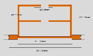
Fig. 1- 2D view in IE3D
the microstrip
IJSER © 2011 http://www.ijser.org
International Journal of Scientific & Engineering Research, Volume 2, Issue 12, December-2011 2
ISSN 2229-5518

As shown in the graph clearly that with -3db is 911Mhz and ending frequency with 1.78Ghz so we obtained bandwidth of 875Mhz and cutoff frequency at 1.273Ghz and return loss
-57.07db second rejection band obtained at 2.7Ghz with return loss of -22db so we can say that our proposed filter exhibited two frequency band rejection at different frequency.
4.CONCLUSION
Fig. 2 - 3Dimensional view in IE3D Dimension of proposed filter
Table 1. Dimensions of the proposed Filter


S. No. Parameter Dimension
1 W1 1mm

2 L1 30mm
3 L2 14mm

4 L3 35mm
4 W2 4mm

5 H 1.6mm
6 FR4 4.4
3.RESULT
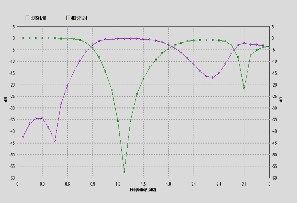
Figure 4. dB VS frequency plot
In this letter, a new design of bandstop filter has been
discussed that improves upon the performance of similar
structures using open stub. By adjusting the configuration of the input and output ports it is possible to change the centre frequency by up to 100 MHz. The measured and simulated response in the frequency domain of the new circuit agree very well when using copper for the circuit conductors, and an equivalent circuit for the circuit has been developed as a design. The results shows that the proposed stop band filter is a wide band filter with an improved bandwidth of 875MHz around the central frequency of 1.273 GHz and return loss -57.07db and second rejection band obtained at 2.7Ghz with return loss of -22db.
5. REFERENCES
[1] Jia-shang hong “microstip dual mode band reject filter”.
[2] Ru-Yuan Yang, Min-Hung Weng, Cheng-Yuan Hung,Han-Jan Chen, and Mau-Phon Houng “Novel Compact Microstrip Interdigital Bandstop Filters”IEEE transactions on ultrasonics, ferroelectrics, and frequency control, vol. 51, no. 8, august 2004.
[3] Jia-Sheng Hong and Michael J. Lancaster, , “microwave filters for
RF/Microwave applications” john willy & sons. ISBN 0-471-22161-9. [4]. D.M. Pozar "Microwave Engineering" John- Wiley,p. 668, 1998.
[5]. Jia-Sheng Hong and Michael J. Lancaster, “Theory and Experiment of Novel Microstrip Slow-Wave Open-Loop Resonator Filters”, IEEE Transactions on Microwave Theory and Techniques, Vol. 45, No. 12, December 1997.
IJSER © 2011 http://www.ijser.org