𝑚1 𝑉𝑑𝑐 𝑐𝑜𝑠 𝛿1
2
International Journal of Scientific & Engineering Research, Volume 4, Issue 8, August-2013 1799
ISSN 2229-5518
Design of Ipfc to Enhance the Power System Stability and Damping of Low Frequency Oscillations
QIS College of Engineering and Technology, Ongole, (A.P), India, gireesh218@gmail.com
Abstract— Interline power flow controller (IPFC) is proposed a new concept for the compensation and effective power flow management of multi-line transmission system. In addition, a supplementary controller for a novel modelling IPFC to damped out low frequency oscillations with considering four alternative damping controllers are proposed. In this project selection of effectiveness damping control signal for the design of robust IPFC damping controller to variations in system loading and faults in the power system are discussed. The presented control scheme not only performs damping oscillations but also the independent inter line power flow control can be achieved. MATLAB simulation results verify the effectiveness of IPFC and its control strategy to enhance dynamic stability.
Index Terms — FACTS controller, Phillips-Heffron model, power system dynamic stability, supplementary controllers, IPFC.
—————————— ——————————
Low frequency oscillations within the frequency in range of 0.2 to3.0 Hz are in the inter connection of large power systems. To increase power system oscillations stability, power system stabi- lizer (PSS) is used. It is simple, effective and economically good [1]. It is necessary to improve the performance of power system to received quality power at the consumer ends. Reactive power compensation is the main measure to keep power system stability and minimum system losses. Flexible AC Transmission (FACTS) devices are found to be very effective controller to enhance the system performance. When compared with FACTS controllers, power system stabilizer may not be able to suppress oscillations resulting from severe disturbances, such as three phase faults at terminals.
Flexible AC Transmission system (FACTS) controllers, such as static VAR compensator (SVC), static synchronous com- pensators (STATCOM) and Unified Power Flow Controller (UPFC) can also be applied for damping oscillations and improve the signal stability of power system by adding a supplementary signal for main control loops [6].
The inter line power flow controller (IPFC) [6] is a new concept of the FACTS controller for series compensation with the unique capability of controlling power flow among multi-lines. IPFC employs two or more voltage source converters (VSCs) with a common dc link. Each VSC can provide series compensa- tion for the selected line of transmission system (master or slave line) and it is capable of exchanging reactive power with its own transmission system.
The damping controller of low power frequency oscilla- tions in the power system must be estimated for a non linear dy- namic model of power system for its accuracy and desirable op- eration at damping of oscillation.
In [10],a linearized model of a system with two or more IPFC line installed, has worked but a SSSC or STATCOM can be employed in the system with a single machine and two lines, out of economic reasons. The active and reactive powers of the lines are not controlled independently. In this project, a single machine
infinite bus is connected with three IPFC lines is used and linear- ized Phillips-Heffron model for the mentioned power system is derived for design of IPFC damping controller. In this, four alter- native damping controllers are to be designed [10, 12].
A power system stabilizer is a device that measures improve- ments in the stability of the system by introducing a supplemen- tary signal to an automatic voltage regulator (AVR). The AVR is an exciter control device which means the terminal voltage of the generator at a constant level, which is one of the most common and economical method. Though generator output is decided by a turbines mechanical torque, it can be changed by transiently changing the excitation system. A power system stabilizer detects the change in generator output power, controls the excitation val- ue and reduces the rapid power fluctuations. PSS is added to ex- citation system to enhance the damping of electric power system during low frequency oscillations. A dynamic modal of PSS is included to investigate the effectiveness in providing positive damping to overcome the undamped electromechanical modes. PSS have been shown to be a effective in stabilizing the modes where are different oscillation frequencies. PSS have been used as a simple, effective, and economical method to increase power system oscillation stability. To design a PSS with better perfor- mance, a several approaches have been applied to PSS design problem and many useful results have been observed. Modern power systems are highly complex and strong non-linearity and their operating conditions can vary over a wide range. Operating conditions of a power system are continuously changing due to the load patterns, electric generation variations, disturbances, transmission topology and line switching. A problem of interest in power industries in which fact controllers could play a major role is the mitigation of low frequency oscillations that often arise between areas in large interconnected power system.
IJSER © 2013 http://www.ijser.org
International Journal of Scientific & Engineering Research, Volume 4, Issue 8, August-2013 1800
ISSN 2229-5518
In the introduction part, a brief introduction of the Interline Pow- er Flow Controller (IPFC) Operation characteristics [6] [15] is presented. General form of the Interline power flow controller employs a number of DC to AC inverters each providing series
formers of the IPFC and by applying Park’s transformation, the per unit values of three-phase dynamic differential equations of IPFC as the three-phase dynamic differential equations of UPFC are obtained.
�𝑉𝑖𝑛𝑗1𝑑 � = � 0 𝑋t1� �𝐼1𝑑� + 𝑉𝑖1𝑑�
�
compensation for a different line. The IPFC can potentially pro-
𝑉𝑖𝑛𝑗 1𝑞
−𝑋t1 0
𝐼1𝑞
𝑉𝑖1𝑞
vide a highly effective scheme for power transmission manage- ment at multiline substations. However within the general con- cept of the IPFC, the compensating inverters are linked together at there DC terminals, as illustrated in figure 1. With this, in addi- tion to provide series reactive compensation, any inverter can be controlled to supply real power to common DC link from its own
𝑉𝑖1𝑑 =
𝑉𝑖1𝑞 =
![]()
𝑚1 𝑉𝑑𝑐 𝑐𝑜𝑠 𝛿1
2![]()
𝑚1 𝑉𝑑𝑐 𝑆𝑖𝑛 𝛿1
2
transmission line. Thus, an overall surplus power can be made
𝐼2𝑑
𝑉𝑖2𝑑
available from the underutilised lines which can be used by other
�𝑉𝑖𝑛𝑗2𝑑 � = � 0 𝑋t2� �
� + � �
lines for real power compensations. In the same manner, some of the inverters compensating overloaded lines or lines with heavy
𝑉𝑖𝑛𝑗 2𝑞
−𝑋t2 0
𝐼2𝑞
𝑉𝑖2𝑞
burden of reactive power flow can be equipped with full two di- mensional, reactive and real power flows, control capability, similar to that offered by UPFC [11]. This arrangement mandates the rigorous maintenance of the overall power balance at the common DC terminal between the two terminals by appropriate control action, using the general principle that the under loaded lines are providing appropriate real power transfer for overloaded
𝑉𝑖2𝑑 =
𝑉𝑖2𝑞 =![]()
𝑚2 𝑉𝑑𝑐 𝑐𝑜𝑠 𝛿2
2![]()
𝑚2 𝑉𝑑𝑐 𝑆𝑖𝑛 𝛿2
2
lines.
𝑑𝑣𝑑𝑐
𝑚1
𝐼1𝑑
𝑚2
𝐼2𝑑
In this IPFC which consisting of a master voltage source converter (VSC-M) and a slave voltage source converter (VSC-S)![]()
![]()
=
𝑑𝑡 2𝐶𝑑𝑐
[𝐶𝑜𝑠𝛿 𝑆𝑖𝑛 𝛿 ] �
𝐼1 𝑞
![]()
� +
2𝐶𝑑𝑐
[𝐶𝑜𝑠𝛿2 𝑆𝑖𝑛𝛿2 ] � �
2 𝑞
and its two transformers and common DC link capacitor (Cdc ). Vinj1 , Vinj2 are voltages of transformers of the lines 1 and 2 re- spectively. While the system is utilised only with two lines, SSSC or STATCOM is installed for the purpose of control functions. In fig .1 m1 ,m2 ,δ1 ,δ2 are the amplitude modulation ratio and phase angle of the control signal of each VSC respectively, which are input signals for IPFC and VB ,VS ,Vinj1 ,V inj2 are the voltages of infinite bus , terminal voltages of the generated and the injected voltages of the master and slave voltage source converters respectively.
Where Xt1 , Xt2 , are the reactance of master and slave injec- tion transformers and Vdc is the dc link voltage and
𝐼1 = 𝐼1𝑑 + 𝑗𝐼1𝑞 , 𝐼2 = 𝐼2𝑑 + 𝑗𝐼2𝑞
The complete dynamic model of the single machine in-
finite bus power system equipped with an IPFC can be developed by above equations.
𝛿 = 𝜔0 𝜔 (1)
𝑃𝑚 − 𝑃𝑒 − 𝐷𝜔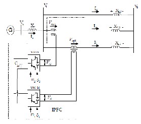
𝜔 =![]()
2𝐻
−𝐸𝑞 + 𝐸𝑓𝑑
′
𝐸𝑞 =
′
𝑑𝑜
𝐸 = − 1
𝑓𝑑 𝑇𝐴
![]()
𝐸 + 𝐾𝐴
𝑓𝑑 𝑇𝐴
(𝑉𝑠0 − 𝑉𝑠 ) (2)
Where Vs ,Vs0 are the terminal voltage and the reference of ter- minal voltage respectively and also ,
𝑇𝑒 =𝑃𝑒 = 𝑉𝑠𝑞 𝐼𝑞 + 𝑉𝑠𝑑 𝐼𝑑 ,![]()
′ ′ 2 2
Fig.1 A single machine infinite-Bus power system installed with IPFC.
𝐸𝑞 = 𝐸𝑞 + (𝑋𝑑 − 𝑋𝑑 )𝐼𝑑 , 𝑉𝑠 = �𝑉𝑠𝑑 + 𝑉𝑠𝑞 , 𝑉𝑠𝑑 = 𝑋𝑞 𝐼𝑞
′ ′
The general pulse width modulation (PWM) is adopted for the IGBT based VSC. By ignoring the resistance of the trans-
𝑉𝑠𝑞 = 𝐸𝑞 − 𝑋𝑑 , 𝐼𝑑 = 𝐼1𝑑 + 𝐼2𝑑 + 𝐼3𝑑 , 𝐼𝑞 = 𝐼1𝑞 + 𝐼2𝑞 + 𝐼3𝑞 (3)
IJSER © 2013 http://www.ijser.org
International Journal of Scientific & Engineering Research, Volume 4, Issue 8, August-2013 1801
ISSN 2229-5518
From figure 1 we can have
𝑉𝑠𝑑 + 𝑗𝑉𝑠𝑞 = 𝑋𝑞 + �𝐼1𝑞 + 𝐼2𝑞 + 𝐼3𝑞 � + 𝑗[𝐸′ − 𝑋′ (𝐼 + 𝐼 + 𝐼 )]
𝑞 𝑑 1𝑑 2𝑑 3𝑑
j(𝑋𝐿3)�𝐼3𝑑 + 𝑗𝐼3𝑞 � = 𝑗(𝑋𝐿1 + 𝑋𝑡1 )�𝐼1𝑑 + 𝑗𝐼1𝑞 � − 𝑉𝑖1𝑑 − 𝑗𝑉𝑖1𝑞 (4)
From above equations [1-4]
𝐼1𝑞 = 𝑉𝑖1𝑑 𝑋𝑞11 + 𝑉𝑖2𝑑 𝑋𝑞21 + 𝑉𝑏 𝑋𝑞𝑏1 sin 𝛿 (5)
area modes of oscillation. A PSS controller is constructed to sta- bilize and damp these modes together with any local rotor-angle oscillatory modes. To this end, a model that is representative of the entire power system, yet which allows the identification of the modes of interest, must be employed. Specifically, the genera- tor and excitation system state equations are linearized and their time derivatives are put into matrix form.
′ 𝑋
(6)
Phillips-Heffron model of a synchronous machine is commonly
𝐼1𝑑 = 𝑉𝑖1𝑞 𝑋𝑑11 + 𝑉𝑖2𝑑 𝑋𝑑21 + 𝑉𝑏 𝑋𝑑𝑏1 cos 𝛿 + 𝐸𝑞
𝐼2𝑞 = 𝑉𝑖1𝑑 𝑋𝑞12 + 𝑉𝑖2𝑑 𝑋𝑞22 + 𝑣𝑏 𝑋𝑞𝑏2 sin 𝛿 (7)
′ 𝑋
𝑑𝑒1
(8)
used in small signal stability analysis and for off-line design of PSS. A cost efficient and satisfactory solution to the problem of oscillatory instability is to provide damping for generator rotor oscillations. The objective of designing PSS is to provide addi-
𝐼2𝑑 = 𝑉𝑖1𝑞 𝑋𝑑12 + 𝑉𝑖2𝑑 𝑋𝑑22 + 𝑉𝑏 𝑋𝑑𝑏2 cos 𝛿 + 𝐸𝑞
𝑑𝑒2
tional damping torque without affecting the synchronising torque
at critical oscillation frequencies.
𝐼3𝑞 = 𝑉𝑖1𝑑 𝑋𝑞13 + 𝑉𝑖2𝑑 𝑋𝑞23 + 𝑣𝑏 𝑋𝑞𝑏3 sin 𝛿 (9)
′ 𝑋
(10)
𝐼3𝑑 = 𝑉𝑖1𝑞 𝑋𝑑13 + 𝑉𝑖2𝑑 𝑋𝑑23 + 𝑉𝑏 𝑋𝑑𝑏3 cos 𝛿 + 𝐸𝑞
Where,
𝑑𝑒3
∆𝑃𝑒 = 𝑘1 ∆𝛿 + 𝐾2∆𝐸′ + 𝐾 ∆𝑉 + 𝐾 ∆𝑚 + 𝐾 ∆𝛿 + 𝐾 ∆𝑚 +
𝐾𝑝𝛿2 ∆𝛿2 (11)
′ ′
∆𝐸𝑞 = 𝑘4 ∆𝛿 + 𝐾3∆𝐸𝑞 + 𝐾𝑞𝑑 ∆𝑉𝑑𝑐 + 𝐾𝑞1 ∆𝑚1 + 𝐾𝑞𝛿1∆𝛿1 + 𝐾𝑞2∆𝑚2 +
𝐾𝑞𝛿2 ∆𝛿2 (12)
∆𝑉𝑠 = 𝑘5 ∆𝛿 + 𝐾6∆𝐸′ + 𝐾 ∆𝑉 + 𝐾 ∆𝑚 + 𝐾 ∆𝛿 + 𝐾 ∆𝑚 +
𝐾𝑣𝛿2 ∆𝛿2 (13)
∆𝑉𝑑𝑐 = 𝑘7 ∆𝛿 + 𝐾8∆𝐸′ − 𝐾 ∆𝑉 + 𝐾 ∆𝑚 + 𝐾 ∆𝛿 + 𝐾 ∆𝑚 +
𝐾𝑐𝛿2∆𝛿2 (14)
From the above equations we arrange in metrics form as
𝑋 = 𝐴𝑋 + 𝐵𝐵
U = [∆𝑚1 ∆𝑚2 ∆𝛿1 ∆𝛿2] T
Where ∆𝑚1 , ∆𝑚2 , ∆𝛿1 , ∆𝛿2 represents the linearization of the
input control signals of the IPFC. The linearized dynamic model
of can be shown by figure 2.This explanation applies to the both an elementary IPFC shown in fig.1 and a multi converter IPFC arrangement. The injection of Vinj1 on system 1 usually results in
an exchange of 𝑃𝑠1 and 𝑄𝑠1 between converter VSC1 and the line.
Commonly the Vinj1,2 voltage is split into its d-q components
which eases the analysis of this system as a whole. The 𝑉𝑖𝑛𝑗1𝑞
component has predominant effect on the line real power, while
the in phase component (𝑉𝑖𝑛𝑗1𝑑 ) has over the lines reactive pow-
er. The reactive power exchange Qs1 is supplied by the converter
itself. However, the active power (PS1 ) imposes a demand to be fulfilled at the dc terminals. Converter VSC-2 is in charge of ful-
filling this demand through the PS1+PS2 =0 constraint.
Since the problem of LFOs can be analyzed from a small-signal stability standpoint, the power system is described by a set of state equations that are linearized. For this particular study, a search is performed for unstable or poorly-damped inter-
Fig.2.Phillips Heffron Model of power system installed with IPFC
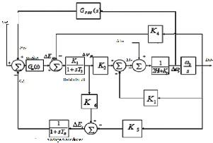
Fig. 3.control block diagram for power system stabilizer
The theoretical basis for power system stabilizer may be illustrat- ed with the aid of block diagram as shown in figure.3, the pur-
IJSER © 2013 http://www.ijser.org
International Journal of Scientific & Engineering Research, Volume 4, Issue 8, August-2013 1802
ISSN 2229-5518
pose of PSS is to introduce a damping torque component. A logi-
cal signal to be used for controlling generator excitation is the
speed deviation ∆𝜔𝑟 . The PSS transfer function, Gpss(s), should
have appropriate phase compensation circuits to compensate for
the phase lag between exciter input and electrical torque.
The damping controllers are designed to produce an electric torque in phase with the speed deviation. The four control param- eters of the IPFC (m1 ,m2 , δ1 ,δ2 ) can be modulated in order to produce the damping torque. The speed deviation ∆w is consid- ered as the input to the damping controllers. The four alternative IPFC based damping controllers are examined in the present work. Damping controller based on IPFC control parameter m1 shall henceforth by denoted as damping controller (m1 ). Similar- ly damping controllers based on m2 , δ1 , δ2 .
The detailed step-by-step procedure for computing the parameters of the damping controllers using phase compensation technique is given below.
1. Computation of natural frequency of oscillation ωn from the mechanical loop.![]()
![]()
ω = �𝐾1 𝜔0
𝑀
2. Computation of ∠𝐺𝐸𝑃𝐴 (phase lag between ∆u and ∆Pe ) at
S=jωn . Let it be 𝛾.
3. design of phase lead /lag compensator Gc :
gain Signal washout Phase compensator
4. Computation of optimum gain Kdc .
The value Kdc is setting to achieve the required amount damping torque can be provided by IPFC damping controller.
The signal washout is the high pass filter that prevents steady changes in the speed from modifying the IPFC input pa- rameter. The value of the washout time constant should be high enough to allow signals associated with oscillations in rotor speed to pass unchanged. From the viewpoint of the washout function, the value of is not critical and may be in the range of 1s to 20s. In this paper Tw equal to10s is chosen References.
0.4
0.3
0.2
0.1
0
-0.1
-0.2
-0.3
-0.4
0 0.5 1 1.5 2 2.5 3 3.5 4 4.5 5
Time (sec)
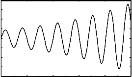
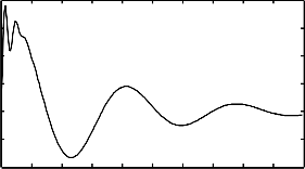
Fig. 5. Angle deviation without using PSS and IPFC
Generally the power system is not in stable condition, when loads are changing and those are effecting on the transmission system. For the different load variations torque an- gle and speed deviations are occurred in power system and there-
kdc
𝑠. 𝑇𝜔
1 + 𝑠. 𝑇𝜔
1+s.T1
1+s.T2
∆Uk
fore power changes may exists in the power system. Without us- ing any controllers the low frequency oscillations and angle devi- ation are increased with respect to time , which is shown in Fig (5). Due to these low frequencies oscillations system losses its
Fig. 4 structure of IPFC based damping controller
The phase lead/lag compensator Gc is designed to provide the required degree of phase compensation. For 100% phase compensa- tion.
stability.
2
1.5
-3
x 10
∠Gc (jωn ) + ∠GEPA (jωn ) =0
Assuming one lead-lag network, T1 = aT2, the transfer function of
the phase compensator becomes,
1+𝑠.𝑎𝑇2
1
0.5
0
![]()
Gc (s) =
1+𝑠.𝑇2
-0.5
Since the phase angel compensated by lead-lag network is equal
to 𝛾 , the parameters and T2 are computed as,![]()
a = 1+sin(𝛾)
1−sin(𝛾)
![]()
1
T2 =
𝜔𝑛
-1
0 0.5 1 1.5 2 2.5 3 3.5 4 4.5 5
Time (sec)
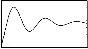
Fig. 6. Speed change with time when PSS is in operating condition
For decreasing of these low frequency oscillations, con- sider a power system stabilizer which is shown in previous and it is in operating condition, the speed deviation in generator side we can control and the waveforms show in Fig (6).
IJSER © 2013 http://www.ijser.org
International Journal of Scientific & Engineering Research, Volume 4, Issue 8, August-2013 1803
ISSN 2229-5518
0.35
system stabilizer, and it will control system stability which is shown in fig.9.
0.3
0.25
0.2
0.15
-3
x 10
9
8
7
6
0.1 5
0.05
0
0 0.5 1 1.5 2 2.5 3 3.5 4 4.5 5
Time(sec)
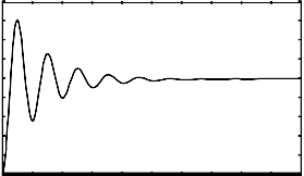
Fig. 7. Angle deviation with PSS
Similarly, with the installation of power system
4
3
2
1
0
0 0.5 1 1.5 2 2.5 3 3.5 4 4.5 5
Time (sec)
stabilizer we can also control the angle deviations shown in above Fig (7) and controls low frequency oscillations in trans- mission system. By controlling of these low frequency oscilla- tions we will try to stabilize the system stability.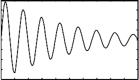
0.08
0.06
0.04
0.02
0
fig. 10. Angle deviation with IPFC in operating condition
Especially, by the controlling of angle deviation in interline powerflow controller with respect to time as shown in fig.10 and which are to be controlled in minimum time compared to PSS.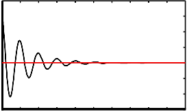
0.03
0.025
-0.02
-0.04
-0.06
-0.08
0 0.5 1 1.5 2 2.5 3 3.5 4 4.5 5
Time(sec)
0.02
0.015
0.01
0.005
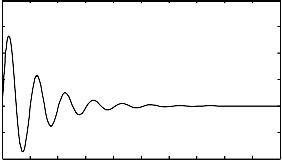
Fig. 8. Phase angle deviation when IPFC in operating condition
In Fig (5), the low frequency oscillations are increased with different loads in power system which is installed with inter-
0
-0.005
0 0.5 1 1.5 2 2.5 3 3.5 4 4.5 5
Time (sec)
line power flow controller in series with transmission system and it controls phase angle and then speed deviations in system which is shown in Fig (8).
-4
x 10
Fig. 11. Mechanical and electrical power flow response with IPFC
Both controlling of speed deviation and angle deviation in power system with IPFC, the transmission system stability will be in- creased. And also the power flow to be controlled as shown in fig.11. In
2
1.5
1
0.5
0
-0.5
-1
0 0.5 1 1.5 2 2.5 3 3.5 4 4.5 5
Time (sec)
Fig. 9. Speed changes with IPFC is used
The interline power flow controller will control the
speed deviations with in minimum time when compared to power
the waveform mechanical power and electrical power of Power system will be controlled in transmission system.
In this project, considering a single machine infinite bus power system which is operated in stable condition, for the sudden changes in the loads the changes occurred in speed, torque angle due to low frequency oscillations. Due to this, the power transfer capability is decreased and the system loses its stability. To avoid these low frequency oscillations power systems stabilizer and Interline Power Flow controller controllers are employed in pow- er system, which is discussed in simulation results. Also better performance and stability is achieved by these controllers with
IJSER © 2013 http://www.ijser.org
International Journal of Scientific & Engineering Research, Volume 4, Issue 8, August-2013 1804
ISSN 2229-5518
less time ellapse, which are shown in resultant waveforms. Pow- er system stabilizer can control the lows frequency oscillations and speed deviations consisting of large time to stabilize the sys- tem when compared to Interline power flow controller which is decreased in this project. IPFC is controlled the power flow with- in the less time to reach system stability point.
[1]. Li-Jun Cai and Istvan Erlich, "Simultaneous Coordinated Tuning of PSS and FACTS Damping Controllers in Large Power Systems", IEEE Transac- tions on Power Systems, Vol. 20, NO.1, pp. 294-300, February 2005.
[2]. H. F. Wang, “Selection of robust installing locations and feedback of FACTS-based stabilizers in multi-machine power systems,” IEEE Trans. Power Syst., vol. 14, no. 2, pp. 569–574, May 1999.
[3]. X. Lei, E. N. Lerch, and D. Povh, “Optimization and coordination of damp- ing controls for improving system dynamic perfo rmance,” IEEETrans. Power Syst., vol. 16, pp. 473–480, Aug. 2001.
[4]. J. J. Sanchez-Gasca, “Coordinated control of two FACTS devices for damp-
ing inter-area oscillations,” in IEEE PES Summer Meeting, Berlin, Germa- ny, July 1997, IEEE paper: PE-802-PWRS-0-06-1997.
[5]. P. Pourbeik and M. J. Gibbard, “Simultaneous coordination of power- system stabilizers and FACTS device stabilizers in a multimachine power system for enhancing dynamic performance,” IEEE Trans. Power Syst., vol. 13, no. 2, pp. 473–479, May 1998.
[6]. L.Gyugyi, k.k.sen, C.D.Schauder, "The Interline Power Flow Controller Concept: A New Approach to Power Flow Management in Transmission Systems", IEEEIPES Summer Meeting, Paper No. PE316-PWRD-0-
071998, San Diego, July 1998.
[7]. Gyugyi, L., A Unnified Power Flow Control Concept for Flexible AC Transmission Systems, IEE PROCEEDINGS-C, Vol. 139, No. 4, July
1992.
[8]. Sen, K. K., SSSC - Static Synchronous Series Compensator: Theory, Mod- eling, and Applications, IEEE Transactions on Power Delivery, Vol. 13, No. I, January 1998. PE-862-PWRD-0-04- 1997, IEEE PES Summer Meeting, Berlin, Germany.
[9]. Sen, K. K. and Stacey, E. J., UPFC - Unified Power Flow Controller: Theo- ry, Modeling, and Applications, PE-282-PWRD- 0- 12- 1997, IEEE PES Winter Meeting, Tampa, USA
[10]. Kazemi, A.; Karimi, E, "The Effect of Interline Power Flow Controller (IPFC) on Damping Inter-area Oscillations in the Interconnected Power Systems," Industrial Electronics, 2006 IEEE International Symposi- um,volume 3, pp. 1911 - 1915, July 2006.
[11]. H.F.WANG: "A Unified Model for the Analysis of FACTS Devices in
Damping Power System Oscillations-Part III: Unified Power Flowcontrol- ler, " IEEE Transactions on Power Delivery, Vol. 15, No.3, pp.978-983, Ju- ly 2000.
[12]. H. F.Wang and F. J. Swift, “An unified model for the analysis of FACTS devices in damping power system oscillations Part I: Single-machine infi- nite-bus power systems,” IEEE Trans. on PWRD, no. 2, 1997.
[13]. Interline Power Flow Controller Based DampingControllers for Damping Low Frequency OscillationsM. R. Banaei, A. Kami Azarbaijan University of Tarbiat Moallem, Tabriz, Iran
[14] D. Arnautovic and J. Medanic, “Design of decentralized multi-variable excitation controller in multi-machine power systems by projective con- trols,” IEEE Trans. Energy Conversion, vol. EC-2, no. 4, pp. 598–604, Dec. 1987.
[15]. N. G. Hingorani and L. Gyugyi, Understanding FACTS. iscataway,
NJ: IEEE Press, , 2001.
The author wish to thank mr.Gireesh Kumar Devineni, assis- tant professor,QIS College of engineering and technology and also author would like to express sincere thanks to Qis College of Engineering and Technology for providing the lab facilities and encouragement during the research work.

Authors Profile

Narasimharao Nakka is presently pursuing his M.Tech in Power System Control And Automation. He has received his B.Tech degree in E.E.E from JNTU Ka- kinada, India in 2010.
Gireesh Kumar Devineni received his M.Tech (PED) degree from SRM Univer- sity, Chennai, India 2011 . He received B.Tech (EEE) degree from JNTU Anantapur. He is currently working as Assistant Professor in QIS College of En- gineering and Technology, Ongole , A.P, India.
IJSER © 2013 http://www.ijser.org