International Journal of Scientific & Engineering Research, Volume 4, Issue 6, June-2013
ISSN 2229-5518
2623
Design of Dielectric Resonator antenna with band notched Characteristics for UWB applications |
Corresponding author : Padmawati kumari |
27/04/2013 |
In this paper, th e design of dielectric reso nator antenna with elliptical patch and dual band notch ed characteristics for UWB applications is proposed. Th e size of the antenna is 40x40x1.6 m m3.Th e CP W ground plane of this antenna is like a half circle. The antenna consists of elliptical shape radiating patch with
50Ω transmissio n line. Two U- slots are inserted in the middle of the elliptical patch to achieve the dual ban d notched characteristics. Th e centre frequenci es of two notched bands can be adjusted by modifying the leng th and width of i nserted U slots. The proposed ultra-wideband (UWB) anten na is optimized to operate in the frequency range from 3 to 11 GHz for VS WR < 2.Good agreement is achieved between the simulated and measured results. These results also show good performances in terms o f antenna gain and radiatio n patterns. With these featu res, this antenna is expected to be good cand idate in various UWB systems.
IJSER © 2013 http://www.ijser.org
Printed with pdfFactory Pro trial version - purchase at www.pdffactory.com
International Journal of Scientific & Engineering Research, Volume 4, Issue 6, June-2013
ISSN 2229-5518
2624
1 Padmawati kumari, 1 D ilip Kumar B isoyi, 2 Santanu Ku mar B ehera
1 Department of Ph ysics
2 Department of Electro nics and C ommun ication Engi neering
N ational institute of Technology, Rourkela, Odisha
a nshu.pa dma@g mail.com, dkb isoyi@ nitrkl.ac.in, sk beh era @ni trkl.ac.in
In this paper, the d esign of dielectric resonator anten na with elliptical patch and dual band notched characteristics for U WB applications is proposed. The size of the antenna is 40x40x1.6 m m3.The CPW ground plane of this antenna is like a half circle. The antenna consists of elliptical shape radiating patch with
50Ω transmissio n line. Two U- slots are inserted in the middle of the elliptical patch to achieve the dual ban d
notched characteristics. Th e centre frequenci es of two notched bands can be adjusted by modify ing the length and width of inserted U slots. The proposed ultra-wideband (UWB) anten na is optimized to operate in the frequency range from 3 to 11 GHz for VS WR < 2.Good agreement is achieved between the simulated and measured results. Th ese results also show good performances in terms o f antenna gain and radiatio n patterns. With these features, this anten na is expected to be good cand idate in variou s UWB systems.
Key words: Ultra wide band, dual band no tched, U shaped slots, VSWR, C PW (Coplan ar waveguide)
1. Introduction
Ultra-wideband (UWB) co mmunicatio n systems attract great attention in the wireless world because of th eir advantages, including high speed data rate, extrem ely low spectral density, high precision rangi ng, precisio n, low cost, and low complexity, The Fed eral Commu nication Commission (FCC) has allowed 3.1-10.6G Hz unlicens ed band fo r UW B communication [1]. Challenges in the d esign of UWB antennas are the impedance matchi ng, the compact size of the antenna, high effici ency, avoiding th e i nterf erence pro blem, an d gettin g constant uniform radiation pattern within operating b and. The UWB system required the U WB antenna of unique features such as transmitting and rec ei ving electromag netic en ergy in shorter durations and avoidin g frequency dispersive a nd space dispersive [2] . Several schemes have been suggested in recent years the ultra-wide band antennas. S om e UWB antennas are much mo re complex than oth er existing single, dual ban d m ultiband antennas. It is a great challen ge to d esign and fabricate di electric reso nator anten nas (DRA) for UWB applications,
Dielectric resonator an tenn as (DRAs) were fi rst introduced by Long et al in 1983[3].D iff erent shapes of DRA has been designed and studied for various applications [4]. For exam ple, stacked DRs with diff erent materials have been studied by Shum and Luk and Kishk et.al have purposed a wideban d DRA by using stacked DRs with different materials to obtain multi resonance operations. F ollowi ng this other con figurati ons of DR are also studied like tetrahedron and triangular shape DR, L shape and T shape DRs as an anten na [5]. Different feeding m echanism have been also in troduced to en hance th e bandwidth and for good coupling b etween DR and feed. Lianget.al have been used H shaped and L shaped dielectrics wi th i nverted trapezoi dal patch feed to achieve a bandwidth from 3.87 to8.17 GHz [6]. In addition, few of these designs can achieve a bandwidth range mo re then 3:1, which can be applied to co mm ercial systems with ultra- wideband from 3.1 to 10.6 GHz [7].Th e U W B antennas presented in the literatu re mainly focus on the slot and m onopole antennas. In this pap er we propose a Hybrid DRA for UWB applications. The DRA consists of th ree parts: a dielectric
reso nator in wh ich elliptical shape patch structure
2
IJSER © 2013 http://www.ijser.org
Printed with pdfFactory Pro trial version - purchase at www.pdffactory.com
International Journal of Scientific & Engineering Research, Volume 4, Issue 6, June-2013
ISSN 2229-5518
2625
has been remov ed, s econd part is an elliptical patch and third part is C PW fed ground plane of half circle shape. In addition , despite the approval of the FCC for UWB to o perate over 3.1-10.6 GHz, there are som e other existi ng narrow band services that already occu py frequencies in the UWB ban d such as IEEE 802.11a in the USA(5.1-
5.35 GHz.5.47-5.725 GHz)[8]. In som e European
and Asian coun tri es, world po rtability fo r microwave access (WiMax) serv ice from 3.3 -3.6
GHz also operates in the UWB band. So it is nec essary to notch out portions of these bands in order to avoid interference. For the abov e purpose, a simple CPW fed UWB DRA with dual band notch characteristi c is proposed and discussed here. Two U slots structures are inserted in the m iddle of the radiating elliptical patch to notch out two frequency bands. The tuning of notched centre frequencies is done by changing the p rop erties of dielectric resonato r and the thickness of U slots.
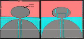
The geom etry of purposed UWB antenna is shown in the figure 1. This antenna is denoted by anten na A. Two U slots structures are removed from th e elliptical patch to get band n otched characteristics and this antenna is denoted as an antenna B.
The anten na B was fab ricated on the FR4
substrate of dielectric constant (ℇr=4.4) with a
thickness 1.6 mm.
From these structu res we can see one elliptical patch structure is fed by a CPW transmission line which is connected with a SMA connector of 50Ω, Since CPW feeding is used to simulate the structure and cost of fabrication can be reduced due to this.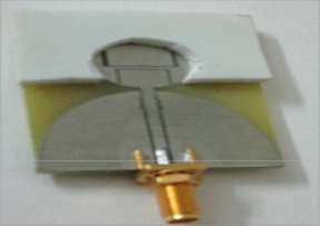
The parameter of radiatin g patch is a=6 mm and b=9 mm respectively. The dimensi on of DR is about 18X40mm2. Th e elliptical patch portio n is rem oved fro m this DR for better im pendence matching. The feed structure is cut out from the ground plane, th e impendence band width o f th e proposed antenna is b roa dened by cutting two extrude arcs beside the upper surface of the feed.
3. Single and dual n otched UWB antenna and results
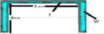
To avoid i nterf erence f rom IEEE 802.11a and WLAN system, a band notched function is desirable for UWB system. In order by etching two U slots in the middle of the radiating elliptical patch we can notch two frequency bands 3.3-3.6 and 5-6GHz.Since th e design concept of notched function is to adjust the slot to be approximately half wavelength of the desire notched frequency.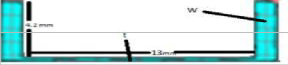
3
IJSER © 2013 http://www.ijser.org
Printed with pdfFactory Pro trial version - purchase at www.pdffactory.com
International Journal of Scientific & Engineering Research, Volume 4, Issue 6, June-2013
ISSN 2229-5518
2626
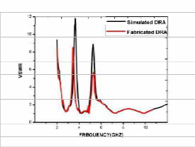
which is show n in Table 1.The V SWR measured and simulated results are also compared in the fig
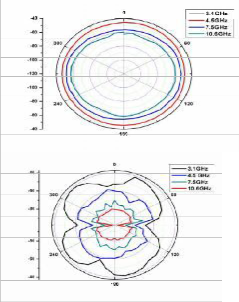
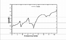
5. The m easurement results of VSWR were carri ed out with a network analyzer. The rad iation patterns of measured DRA was also done i n anechoic chamber. Fig 6 shows the plot of measured radiation patterns at four different frequ enci es. Th ese results are app roxi mately acceptable fo r UWB system s. The gain of DRA is
shown in fig 7.![]()
![]()
c
2L
![]()
2
Er1+Er2
where c is the speed of light in vacuum, L is the
length of slots and lll r1 an dlllr2 are the relative
permittivity of the substrate and dielectric
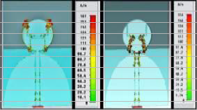
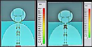
resonator respectiv ely. From eq 1 the length of slot is taken into consideration to determine to length of slot and we can adjust it according to our need for fa brication. Th is condition is applicable to both the U and C slots. But in the U slots the thickness of sides of U slots can also tune the centre frequency and this is to be studied in this paper. Fig 8(a, b, c, d) are showing the surface current distribution of current at four di fferent frequ encies. Th e surface current flows arou nd th e slot of the radiating patch. But in notched conditions at frequencies 3.3 and 5.3 G Hz, the surface current in the antenna will cause destructive i nterference wh ich make the antenna irrespo nsive in that region.
Based on the optimal values obtained from the parametric studi es, exp erimental prototyp es for the UWB DRA were fabricated and m easured. fig 4 shows the return loss of an antenna with and without DR and also with notched conditions. The optimizati on value of data which is used in the simulation p rocess is analyzed bef ore fab ricatio n
IJSER © 2013 http://www.ijser.org
Printed with pdfFactory Pro trial version - purchase at www.pdffactory.com
International Journal of Scientific & Engineering Research, Volume 4, Issue 6, June-2013
ISSN 2229-5518
2627

5
IJSER © 2013 http://www.ijser.org
Printed with pdfFactory Pro trial version - purchase at www.pdffactory.com
International Journal of Scientific & Engineering Research, Volume 4, Issue 6, June-2013
ISSN 2229-5518
2628
A compact dual band notched UWB an tenna is pres en ted and investigated. The radiatio n patterns in the H plane are omnidi rectional over the entire ultra-wideband and the E plane of the antenna is like a dipole. The gain of antenna also shows stable with the sharp decreas e characteristic in the no tched frequ ency band. Consequently the proposed antenna is expected to be good candidate in various UWB applications.
The author would like to thank Prof Su neetTuli and Prof Mahesh Ad egaonkar department of applied el ectronics, IIT D elhi to provide me simulation and m easurem ent facilities in their “RF and Micro wave Circuit Labo ratory”.
[1] “Fed eral communication commission Revisi on Of part 15 of the commission’s Rules regarding Ultra wideband Transmission System from 3.1 to 10.6 GHz ,” in Federal communicatio n Com mission , Washington, D ; ET-Docket ,2002pp. 98-153, FCC.
[2] Qin g- Xin Chu and Ying-Ying Yang, “A compact
ultra- wideband antenna with 3.4/5.5 GHz dual notched ba nd characteristics” IEEE Trans.Propag, vol 56, 3637-3644.2008.
[3] Yi cheng Lin, Kuan Jung Hun g, “Compact ultra-
wid eban d rectangular aperture anten na and band notch ed D esig ns” IEE E Trans. Anten nas Propag,v ol 54, pp. 3075-081, 2006.
[4] K. P. Esselle and T. S. Bird, "A Hybrid- Resonato r Antenna: Experimental Results" IEEE Trans. A nten nas Pro pagation, vol 53,pp.
870-871, 2005.
[5] C.Y Huang, S .A Huang and C.F Yang, “Band notched ultra-wideband circular slot anten na with inverted C shaped parasitic strip, “Electron. Lett. vol 44, 891- 892, Jul 2008.
[6] A. A Alshehri, A. R Sebak and T.A D enidni, “Printed UWB elliptical antenna with a
frequency band notch ed function,” Micro wave
Opt. Technology letters, vol 51, 860-864,
2009.
[7] K. S. Ryu and A. A Kishk “UWB Dielectric resonator antenna having Consistent Omni directio nal pattern an low cross polarization” 0018-92 6 X/2011 ,IEEE
[8] T. A .Denidni and Z. W eng “Hybrid ultra- wideband DRA and band notched desig ns” IET Microwave Antennas Pro pag. 2011, vol5, 450-
458
[9] CST Microwave studio 2010
6
IJSER © 2013 http://www.ijser.org
Printed with pdfFactory Pro trial version - purchase at www.pdffactory.com
International Journal of Scientific & Engineering Research, Volume 4, Issue 6, June-2013
ISSN 2229-5518
2629
IJSER © 2013 http:1/www.ijser.org
Printed with pdfFactory Pro trial version- purchase at www.pdffactory.com