International Journal of Scientific & Engineering Research, Volume 2, Issue 12, December-2011 1
ISSN 2229-5518
Design and simulation of Hybrid Active Power Filter using the Adaptive Fuzzy Dividing Frequency- Control Method
Mr. Nagaraju Devarashetti, Mr.Y.Rajasekhar Reddy, Prof. P.V. Kishore
—————————— ——————————
IN order to solve more serious harmonic problems of the grid, the passive power filter (PPF) is often used at the point of common coupling (PCC) conventionally. However, it has many disadvantages (mistuning, resonance, instability,
•etc.), which discourages its implementation [1]—[5]. The use of the active power filter (APF) to mitigate harmonic problems has drawn much attention since the 1970s [1], [2]. APFs seem to be a feasible solution for eliminating harmonic currents and voltages. They are usually in parallel to harmonic loads and, been a trend to develop the shunt APF that can be used under non sinusoidal supply voltages, where the voltages at the PCC of the APF are harmonics- contaminated and caused by other connecting nonlinear loads in the APF application environment [6], [7]. However, they are limited by high cost, low-power capacity, and are difficult to use in high-voltage grids. Another solution for the harmonic problem is to adopt a hybrid active power filter (HAPF) [4]. The HAPF is the combination of active and passive power filters. The aim in the HAPF design is to complement or enhance the performance of the active power filter or passive power filter by adding passive or active components to its structure. HAPF is categorized in parallel hybrid filters (SHAPFs) based on the used active filter type. A series of PHAPFs was proposed after the 1990s [8]—[10]. Cheng et at. Proposed a new hybrid active power filter to achieve the power-rating reduction of the active filter [10]. But the active power filter still bears the fundamental voltage in this design. In this paper, a novel HAPF with injection circuit was proposed. The novel topology has great promise in reducing harmonics with a relatively low capacity APF.
For harmonic current tracking controls, there are two schemes [11]—[ 15]: One is the linear current control,
such as ramp comparison control, deadbeat control, sinusoidal internal model control, generalized integrators control, etc.; the other is nonlinear current control.
Hysteresis control has the advantage of simplicity, but leads to a widely varying switching frequency. This limitation has been improved with variable hysteresis band switching strategies but it requires a complex controller to achieve satisfactory performance. Predictive current control offers the best potential for precise current control, but the implementation of a practical system can be difficult and complex.
Ramp comparison control using a proportional- integral (PI) regulator has a long history of use. When the reference current is a direct signal, as in the dc motor drive, zero steady-state error can be secured by using a conventional PI controller. When the reference current is a sinusoidal signal, as in the ac motor drive, would lead to steady-state error due to the finite gain at the operating frequency. This drawback can be solved if the current control is executed in a synchronous-coordinate reference frame. However, it is more complex and requires more hardware or software for implementation because it demands transferring the measured currents to a synchronous frame, and subsequently transforming the output of the PI regulator back to a stationary frame to drive the ramp comparison controller. Sinusoidal internal model control also requires more hardware or software for implementation.
IJSER © 2011 http://www.ijser.org
International Journal of Scientific & Engineering Research, Volume 2, Issue 12, December-2 2
ISSN 2229-5518
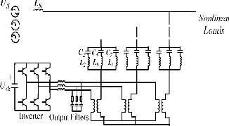
Fig. 1. (b) Topology of the novel HAPF.
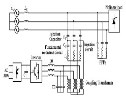
Fig. 1. (a)Topology of the shunt hybrid APP.
In this paper, an adaptive fuzzy dividing frequency- control method composed of a generalized PI control unit and fuzzy adjustor unit was proposed. In the new control scheme, the generalized PI control unit is used to achieve dividing frequency control; the fuzzy adjustor unit is used to adjust the parameters of the PI control unit to produce better adaptive ability and dynamic response. At the same time, the control strategy is generally useful and applicable to other active filters. It is implemented in an IHAPF with a
100-kVA APF installed in a copper mill in Northern China. Simulation and application results have shown that the new dividing frequency-control method is not only easy to be calculated and implemented, but also very effective in reducing harmonics.
A. Topology of the Novel HAPF
The parallel HAPF has the advantages of easy
installation and maintenance and can also be made just by
transformation on the PPF installed in the grid. Fig. 1 shows a PHAPF that is in use now [3]. To reduce the power
of APFs, a PPF has been designed for some certain orders of harmonics. As in Fig. 1 C2, L2, C5, L5, and C7 and L7 make up a PPF to compensate the second, fifth, and seventh harmonic current, while the APF is just used to improve the performance of PPF and get rid of the resonance that may occur. So the power of the filter can be reduced sharply, usually one-tenth of the power of the nonlinear load, which enables the APF to be used in a high-power occasion. HAPF is expected to compensate for reactive power as well as damp harmonics in the grid, and all of the reactive power current will go through APF.
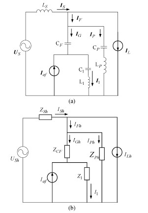
Fig. 2 . Single-phase equivalent circuit. (a) Single-phase equivalent circuit. (b) Single-phase equivalent circuit with the effect of a harmonic source.
To further decrease the power of APP, a novel configuration of the hybrid APF is proposed [16]. L1 and C1 tune at the fundamental frequency, and then compose the injection branch with CF.The APF, shunted to the fundamental resonance circuit, is directly connected in series with a matching transformer. Therefore, the novel HAPF (IHAPF) is formed. The PPF sustains the main grid voltage and compensates for the constant reactive power, while the fundamental resonance circuit only sustains the harmonic voltage, which greatly reduces the APP power and minimizes the voltage rating of the semi• conductor switching device. So it is effective to be used in the 6- kv/9-kv medium-voltage grid.
IJSER © 2011 http://www.ijser.org
International Journal of Scientific & Engineering Research, Volume 2, Issue 12, December-2011 3
ISSN 2229-5518
In order to clarify the compensation principle of IHAPF, a single-phase equivalent circuit is shown in Fig. 2, where APF is considered a controlled current source Iaf and the nonlinear load is considered to be a harmonic current source IL In Fig. 2, Us and LS are the supply voltage and equivalent inductor of the grid CF, and C1, L1, CP, and LP are the injection capacitor, fundamental resonance capacitor, fundamental resonance inductor, and the PPF capacitor and inductor, respectively.
Fig. 2(b) is the equivalent circuit of the IHAPF only considering the harmonic component of the system. Zsh, Zph, ZCF, and Z1 represent system impedance, PPF impedance, the impedance of the injection capacitor, and the fundamental resonance impedance, from 2(b)
B. Control Strategy of IHAPF
There are two types of harmonic detection methods
which play important roles in the control strategy of HAPF.
Load current detection: This method detects the load
current ILh, which flows downstream of the point of installation, and then extracts the harmonic current ILh From IL.
Supply current detection: This method detects the
supply current IS which escapes upstream of the point of installation, and then extracts harmonic current I Sh from Is
1) Control Strategy Based on Load Current Detection:
This method detects the load harmonic current and the APF![]()
is controlled as
(2)
From (1) and (2) and when only harmonic current is considered, the supply harmonic current should be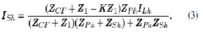
![]()
Equation (3) can be written as
It can be seen that the characteristic of PPFs is optimized and the harmonic impedance of the grid is increased, which improves the performance of harmonic elimination. However, the possibility of resonance between the IHAPF and the grid cannot be avoided, and it increases the
difficulty of parameter design. Moreover, it is not suitable to be used in the situation where the impedance of the grid changes at high frequency.
2) Control Strategy Based on the Supply-Current Detection: This method detects the supply harmonic current I Sh, and the APF is considered as a controlled current source
Iaf = K Ish (5)
where K is the controlled gain of I Sh From (1) and (5), the supply current should be
![]() (6) Equation (6) indicates that it is possible to eliminate the
(6) Equation (6) indicates that it is possible to eliminate the
influence of the load harmonic current and supply
harmonic voltage as low as possible if K is large enough.
Moreover, if the supply harmonic voltage is not considered,
that is Ush=0.
![]() (7)
(7)
Equation (7) shows that Figs. 3 and 2(b) are equivalent, where ![]() According to Fig.3, the APF of the IHAPF tends to be a harmonic resistance, which is in series with the Ls. When Z is large enough, the harmonic current flowing into the grid is nearly zero. Thus, it has a good performance in harmonic elimination. At the same time, it can restrain the possibility of parallel resonance between the IHAPF and the grid.
According to Fig.3, the APF of the IHAPF tends to be a harmonic resistance, which is in series with the Ls. When Z is large enough, the harmonic current flowing into the grid is nearly zero. Thus, it has a good performance in harmonic elimination. At the same time, it can restrain the possibility of parallel resonance between the IHAPF and the grid.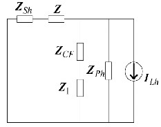
Fig. 3. Single equivalent circuit by just considering ILh
As stated before, it can be found that for the sake of compensating harmonic current, the control strategy based on the detection of load harmonic current is a good choice. But the possibility of resonance between the IHAPF and the grid cannot be avoided, and it increases the difficulty of the IHAPF parameter design. If the control strategy based on supply current detection is used, IHAPF can eliminate not only the harmonic current, but also the possibility of parallel resonance between IHAPF and the grid will be restrained. So the control strategy based on the supply
IJSER © 2011 http://www.ijser.org
International Journal of Scientific & Engineering Research, Volume 2, Issue 12, December-2011 4
ISSN 2229-5518
current detection is used in this paper.
Based on the detected harmonic current Ish in the grid, the APF can compensate harmonics by making the inverter generate harmonics whose magnitude is equal to Ish but the phase is the opposite of it. However, as parallel HAPFs in Figs. 1 if APF generates harmonics as the same order as PPF, the performance of the PPF may be counteracted, even if an accident occurs for the over current of PPF. That is to say, just for HAPF, there is no need to control some order harmonics, as it can waste the compensation capacity easily [16]. This is one reason why we need to adopt the dividing frequency-control method.
Taking the IHAPF, for example, as for the sake of simplicity, the influence of PPF and the equivalent impedance of the grid have not been considered. Therefore, the single-phase equivalent circuit can be received as shown in Fig. 4, where Uo is the output voltage of the inverter equivalent to the primary side of the coupling transformer; LO’ and CO’ are the inductor and capacitor of output filter, respectively; and ILH is the harmonic current injected to the grid.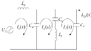
Fig. 4. Single-phase equivalent circuit.
Fig. 5. Bode diagram of G(s).
From Fig.5, it can be seen that the amplitude-frequency characteristic of the transfer function just has one resonance point beyond the fundamental frequency, and the phase- frequency characteristic is divided by this resonance pulsations 1 and the phase position is changed from 90° to
—90°. Obviously, when the harmonic of both sides of 1
needs to be compensated, it is hard to obtain ideal performance if the single control strategy is adopted without considering the influence of phase. For different kinds of HAPF, the differences of structure and parameters will lead to the discrepancy of 1. Moreover, the rule of phase change may be different. Therefore, in order to achieve good performance, the phase and amplitude should be considered at the same time. And, thus, dividing frequency control must be adopted.
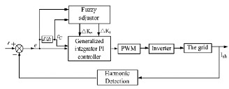
The conventional linear feedback controller (PI controller, state feedback control, etc.) is utilized to improve the dynamic response and/or to increase the stability margin of the closed loop system. However, these controllers may present a poor steady-state error for the harmonic reference signal. An adaptive fuzzy dividing frequency control method is presented in Fig.6, which consists of two control units: 1) a generalized integrator control unit and 2) a fuzzy adjustor unit. The generalized integrator, which can ignore the influence of magnitude and phase, is used for dividing frequency integral control, while fuzzy arithmetic is used to timely adjust the PI coefficients..
Fig.6. Configuration of the adaptive fuzzy dividing frequency controller.
Since the purpose of the control scheme is to receive a minimum steady-state error, the harmonic reference signal r is set to zero. First, supply harmonic current is detected. Then, the expectation control signal of the inverter is revealed by the adaptive fuzzy dividing frequency controller. The stability of the system is achieved by a proportional controller, and the perfect dynamic state is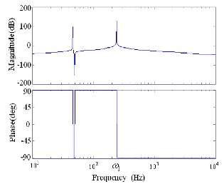
IJSER © 2011 http://www.ijser.org
International Journal of Scientific & Engineering Research, Volume 2, Issue 12, December-2011 5
ISSN 2229-5518
![]()
received by the generalized integral controller. The fuzzy adjustor is set to adjust the parameters of proportional control and generalized integral control. Therefore, the
proposed harmonic current tracking controller can decrease the tracking error of the harmonic compensation current, and have better dynamic response and robustness.
A. Generalized Integral Controller
The generalized integral PI controller carries out the
dividing frequency control of the sinusoidal signal. Similar
to the direct signal case, the generalized integrator just works on the amplitude, but has no effect on its frequency
and phase. So the amplitude integration of this signal can be written as y(t) = At sin(wt + φ) (8). Further defining an auxiliary signal x(t) = A cos(wt + φ) (9), the Laplace transforms of the three signals are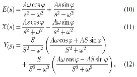
So,
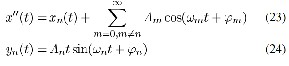
From (19), it can be seen that (13) comes into existence all the same even when the frequency of the sinusoidal signal has a small deviation When is far bigger than 1, there is![]()
As for Y’(S)![]()
So when the frequency deviation is large, the amplitude integration Y’(s) will be zero, And so, for the three sinusoidal signals![]()
![]()
Where
When the frequency of the sinusoidal signal has a deviation
![]()
The auxiliary signal and integration signal can be shown as![]()
And then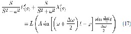
![]()
When the frequency deviation is small, there is![]()
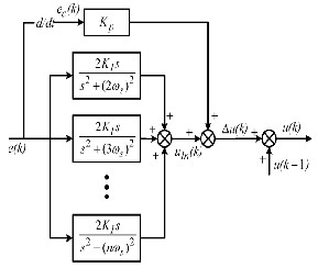 Fig.
Fig.
7. Configuration of the generalized integrator PI controller.
So (17) can be written as![]()
According to the previous analyses, when
their Laplace transforms can be written as
IJSER © 2011 http://www.ijser.org
International Journal of Scientific & Engineering Research, Volume 2, Issue 12, December-2011 6
ISSN 2229-5518
![]()
From (27), it can be seen that (13) has a selectivity of frequency. It indicates that the integration signal yn(t) of a sinusoidal signal en(t) with the frequency w can be obtained based on (27).
At the same time, we can see that![]()
According to (28) and (13), then
where k is the sampling value of the current time, k-1 is the sampling value of the previous cycle, and KP and Ki are the proportional coefficient and integrator coefficient of the PI controller, respectively, and H is a set of harmonic orders that need to be eliminated. In order to eliminate disturb efficiently, the discrete differential coefficient ec(k) can be obtained by adopting (15)
![]()
B. Fuzzy Adjustor
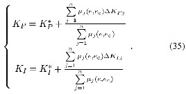
The fuzzy adjustor is used to adjust the parameters of proportional control gain K P and integral control gain K
I, based on the error e and the change of error ec.
![]()
Relative to y(t), ![]() is negligible. thus, the transfer function of the generalized integrator, which has a
is negligible. thus, the transfer function of the generalized integrator, which has a
function of dividing frequency, is![]()
Where K* *
P and K I are reference values of the fuzzy-
![]()
generalized integrator PI controller. In this paper, K*
& K*
In terms of the analysis from before, the block diagram of the generalized integrator PI controller can be obtained by the characteristic of the generalized integrator, shown in Fig. 7.
To reduce count quantity and improve the real time, the incremental iteration algorithm is applied. On the principle of the control quantity of the previous two-control cycle, the output of the generalized integrator is expressed as![]()
The generalized integrator PI controller law is![]()
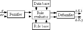
Fig. 8. Block diagram of the fuzzy adjustor unit
are calculated offline based on the Ziegler—Nichols method. In a fuzzy-logic controller, the control action is determined from the evaluation of a set of simple linguistic rules. The development of the rules requires a thorough understanding of the process to be controlled, but it does not require a mathematical model of the system. A block diagram fuzzy-logic adjustor is shown in Fig. 8. In this way, system stability and a fast dynamic response with small overshoot can be achieved with proper handling of the fuzzy-logic adjustor.
Fuzzification converts crisp data into fuzzy sets, making it comfortable with the fuzzy set representation of the state variable in the rule. In the fuzzification process, normalization by reforming a scale transformation is needed at first, which maps the physical values of the state variable into a normalized universe of discourse.
The error e and change of error ec are used as numerical variables from the real system. To convert these numerical variables into linguistic variables, the following seven fuzzy levels or sets are chosen as [17]: negative big (NB), negative medium (NM), negative small (NS), zero (ZE), positive small (PS), positive medium (PM), and positive big (PB).
To ensure the sensitivity and robustness of the controller, the membership function of the fuzzy sets for
e(k), ec(k), Kp, and KI in this paper are acquired from the
IJSER © 2011 http://www.ijser.org
International Journal of Scientific & Engineering Research, Volume 2, Issue 12, December-2011 7
ISSN 2229-5518
ranges of e, ec, Kp, and KI , which are obtained from project and experience. And the membership functions are shown in Fig. 9, respectively.
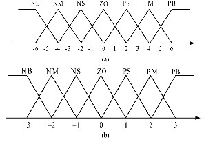
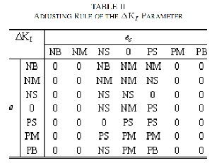
Fig. 9. Membership functions of the fuzzy variable. (a) Membership function of e(k) and ec(k). (b) Membership function of ΔKp and ΔkI.
The core of fuzzy control is the fuzzy control rule, which is obtained mainly from the intuitive feeling for and experience of the process. The fuzzy control rule design involves defining rules that relate the input variables to the output model properties.
For designing the control rule base for tuning ΔKp and ΔkI , the following important factors have been taken into account.
For large values of |e|, a large ΔKp is required, and for small values of |e|, a small ΔKp is required.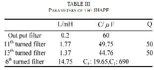
For e.ec > O, a large ΔKp is required, and for e.ec
<0 a small ΔKp is required.
For small values of e, ΔkI is effective, and ΔkI is larger when e is smaller, which is better to decrease the steady-state error. So the tuning rules of ΔKp and ΔkI can be obtained as Tables I and II.
The inference method employs the MAX-MIN method. The imprecise fuzzy control action generated from the inference must be transformed to a precise control action in real applications. The center of gravity method is used to defuzzify the fuzzy variable into physical domain
Simulation results of a 10-kV system have been carried out with software PSIM. The system parameters are listed in Table III. The PPFs are turned at the 11th and 13th,
respectively. The injection circuit is turned at the 6th. In this
IJSER © 2011 http://www.ijser.org
International Journal of Scientific & Engineering Research, Volume 2, Issue 12, December-2011 8
ISSN 2229-5518
simulation, ideal harmonic current sources are applied. The dc-side voltage is 535 V.
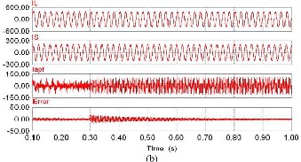
Simulation results with the conventional PI controller and the proposed current controller are shown in Figs. 10 IL,IS, IF,I apf and the error represent the load current, supply current, current though the injection capacitor, current through APF, and error of compensation.
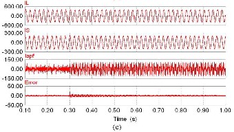
Fig. 10 shows the dynamic response of IHAPF when different controllers are adopted. At 0.3 s, the THD increases from 9.6% to 21.8%. When the conventional PI controller is used, the error can be reduced to ± 20 A in 0.06 s, but there is an obvious steady- state error at 1.0 s all the same. When the generalized integral controller is used, the error reduces to ± 10A at 0.6 s; however, it can only be reduced to ± 30 A in 0.06 s. When the proposed controller is used, the error can be reduced to ±10 A in 0.06 s. It is observed that compared to the conventional PI controller and generalized integral controller, the proposed controller
has better dynamic performance.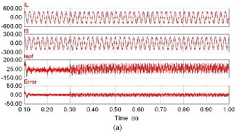
The steady-state performance of the IHAPF when different controllers are used is studied, it revealed that after IHAPF with the conventional PI controller runs, the current total harmonic distortion reduces to 3.8% from 21.8%, and the power factor increases to 0.95 from 0.55. When the conventional generalized integral controller is used, the current THD reduces to 3.3% from 21.8%, while after the IHAPF with the proposed PI controller runs; the current THD reduces to 1.8% from 21.8%. So it can be observed that the proposed current controller exhibits much better performance than the conventional PI controller and the conventional generalized integral controller.
Fig. 10. Simulation results of the dynamic performance. (a) Simulation results with the conventional P1controller. (b) Simulation results with the conventional generalized integral controller. (c) Simulation results with the proposed controller.
A novel hybrid APF with injection circuit was proposed. Its principle and control methods were discussed. The proposed adaptive fuzzy-dividing frequency control can decrease the tracking error and increase dynamic response and robustness.
The control method is also useful and applicable to
any other active filters. It is implemented in an IHAPF with a lOO-kVA APF system in a copper mill in Northern China, and demonstrates good performance for harmonic elimination. Simulation and application results proved the feasibility and validity of the IHAPF and the proposed control method.
[1] L. Gyugyi and E. C. Strycula, “Active ac power filters,”
in Proc. IEEE, md. AppL Soc. Aoou. Meeting, 197fi, pp. 529—
535.
[2] N. Mohan, H. A. Peterson, W. F. Long, G. R. Dreifuerst,
and I. J.Vithayathil, “Active filters for AC harmonic
IJSER © 2011 http://www.ijser.org
International Journal of Scientific & Engineering Research, Volume 2, Issue 12, December-2011 9
ISSN 2229-5518
suppression,” presented at the IEEE Power Eng. Soc. Winter Meeting, 1977.
[3] F. Peng, H. Akagi, and A. Nahae, “A new approach to
harmonic compensation in power system-a combined system of shunt passive and se ries active filters,” IEEE Trons. md. AppL, vol. 26, no. 6, pp. 983—990, Nov. 1990.
[4] C. Madtharad and S. Premrudeepreechacham, “Active
power filter for three-phase four-wire electric systems using
neural networks,” Elect. Power Syst. Res., vol. 60, no. 2, pp.
179—192, Apr. 2002.
[5] H. Fujita and H. Akagi, “A practical approach to harmonic compensation in power system-series connection of passive and active filters,”IEEE Trons. md. AppL, vol. 27, no. 6, pp. 1020—1025, Nov. 1991.
[6] H. Fujita and H. Agaki, “The unified power quality
conditioner: the integration of series and shunt-active
filters,” IEEE Trons. Power Elec• tron., vol. 13, no. 2, pp.
315—322, Mar. 1998.
[7] K. J. P. Macken, K. M. H. A. Dc Brabandere, I. J. L. Dnesen, and R. J. M. Belmans, “Evaluation of control algorithms for shunt active tillers under unbalanced and nonsinusoidal conditions,” in Proc. IEEE Porto Power Tech. Conf., Porto, Portugal, Sep. 10—13, 2001, pp. 1621—1626.
[8] F. Ruixiang, L. An, and L. Xinran, “Parameter design
and application research of shunt hybrid active power
filter;’ Proc. CSEE, vol. 26, no. 2, pp. 106—111, Jun. 2006.
[9] 5. Kim and P. N. Enjeti, “A new hybrid active power filter (APF) topology;’ IEEE Trons. Power Electronics, vol.
17, no. 1, pp. 48—54, Jan. 2002.
[10] 5. Bhattachaya, P.-T. Cheng, Deep, and M. Divan, “Hybrid solutions for improving passive filter performance in high power applications;’ IEEE Trons md. AppI., vol. 33, no. 3, pp. 732—747, May 1997.
[11] L. Malesani, P. Mattavelli, and P. Tomasin, “High performance hysteresis modulation technique for active filters;’ IEEE Trons. Power Electron., vol. 12, no. 5, pp. 876—
884, Sep. 1997.
[12] 5. Fukuda and R. Imamura, “Application of a sinusoidal intemal model to current control of three-phase utility-interface converters,” IEEE Trons. mod. Electron., vol.
52, no. 2, pp. 420—426, Apr. 2005.
[13] X. Yuan, W. Merk, H. Stemmler, and J. Allmeling, “Stafionary-frame generalized integrators for current control of active power filters with zero steady-state error for current harmonics of concern under unbalanced and distorted operating conditions;’ IEEE Trons. mod. AppI., vol.
38, no. 2, pp. 523—532, Mar. 2002.
[14] K. Nisbida, Y. Konishi, and M. Nakaoka, “Current
control implemen• tation with deadbeat algorithm for
three-phase current-source active power filter,” Proc. Inst. Elect. Eng., Electr. Power AppI., vol. 149, no.
4, pp. 275—282, Jul. 2002.
[15] J. H. Marks and T. C. Green, “Predictive transient- following control of shunt and series acfive power filters,” IEEE Trons. Power Electron., vol. 17, no. 4, pp. 574—584, Jul.
2002.
[16] A. Nakajima, K. Oku, J. Nishidai, T. Shiraishi, Y. Ogihara, K. Mizuki,
and M. Kumazawa, “Development of active filter with series resonant circuit;’ in Proc 19th IEEE Annu. Power Electronics Specinlists Conf Rec., Apr. 11—14, 1988, vol. 2, pp.
1168—1173.

NAGARAJU DEVARASHETTI is currently pursuing master of technology program in Power Electronics and Electrical Drives in Mother Teresa Institute of Science and Technology,Sathupally affiliated to Jawaharlal Nehru Technological University, Hyderabad, Andhra Pradesh, India.
E-mail: examnaga@gmail.com
Mr.Y.Rajasekhar Reddy was born in 1982. He graduated from Jawaharlal Nehru Technological University, Hyderabad in the year 2004. He received M.E degree from Anna University, Chennai in the year 2006. He is presently working as Assistant Professor in the Department of Electrical and Electronics Engineering at Mother Teresa Institute of Science and Technology, India. His research area includes DTC and Drives.
Prof. P. Venkata Kishore has obtained his B. Tech degree from S.V. University India, in 1998 and M. Tech degree From S. V.
University India, in 2003. He has 14 years of
teaching experience. He is presently a research scholar at Sathyabama University, Chennai, India. He is working in the area of Power quality improvement using DSTATCOM. Presently he is working as Professor & HOD in Mother Teresa Institute Of Science & Technology,EEE Department,Sathupally.
IJSER © 2011 http://www.ijser.org