Fig. 1 Structure of a Fabry-Perot interferometer
International Journal of Scientific & Engineering Research, Volume 4, Issue 8, August-2013 1854
ISSN 2229-5518
Gaillan H.Abdullah*,Bushra.R.Mahdi**, Farah G.
*g_altayar@yahoo.com,Boshera65m@yahoo.com
In this peaper three designs band-pass filter with different number of layers are presented. These designs are concerned with a theoretical study on optoelectronics. physics to design and
These designs consist of two material TiO2 / SiO2 as high / low index.
analyze band-pass filter
The wavelength range from 600 to 850nm and the design wavelength 700nm. The results show that the effects of angle of incident on the characteristics curve Transmission vs. wavelength for each design. The resulting design approach to push pulse durations further into the single-cycle
regime.
Keywords: Narrow bandpss filter, Design Narrow bandpass filter
The basic design of narrow bandpass filter is constructed on the Fabry-Perot Interferometer. It belongs to the class of interferometers known as multiple-beam Interferometers because a large number of beams is involved in the interferometer. Figure (1) shows the structure of a Fabry- Perot interferometer in diagrammatic form. The Fabry-Perot interferometer consists of two identical parallel reflecting surfaces (A and B) spaced apart a distance dR sR, called “spacer”. In collimated light, the transmission is low for all wavelengths except for a series of very narrow transmission bands in which the half of the central wavelengths are equal to integer times of the optical thickness of the spacer [1].
Fig. 1 Structure of a Fabry-Perot interferometer
IJSER © 2013 http://www.ijser.org
International Journal of Scientific & Engineering Research, Volume 4, Issue 8, August-2013 1855
ISSN 2229-5518
ns and ds are the refractive index and the physical thickness of the spacer.
Θ is the incident angle of the collimated light
λ is the wavelength of the collimated light
φa and φb are the phase change of the light on the reflecting surface A and B. Ta and Tb are the transmittances of the reflecting surface A and B.
Ra and Rb are the reflectances of the reflecting surface A and B.
The amplitude reflection and transmission coefficients are defined as shown. The
basic theory of the multiple-beam interferometers shows that the transmittance for a plane wave is given by
 (1)
(1)
Equation (1) propounds some information of a Fabry-Perot interferometer. The
Analyses are as follows [2].
a- Central wavelength:
Because of the reflectance's of the reflecting surface A and B are not zero, the maxima transmission T=Tmax are happened when λ is at the central wavelength λp, and relationship is as follows.
 (2)
(2)
So, the central wavelengths are given by
IJSER © 2013 http://www.ijser.org
International Journal of Scientific & Engineering Research, Volume 4, Issue 8, August-2013 1856
ISSN 2229-5518
 (3)
(3)
If ![]() the central wavelength of the filter is only dependent on the optical thickness of the spacer layer and the angle of incident. When changing the angle of incident, the central
the central wavelength of the filter is only dependent on the optical thickness of the spacer layer and the angle of incident. When changing the angle of incident, the central
wavelength of the filter will therefore be shifted to the shortwave side of the central wavelength
[3].
b- Halfwidth of pass band:
Normally, the definition of the halfwidth of pass band is the width of the band measured at half the peak transmission. Now let the pass bans be sufficiently narrow, with F being sufficiently large, so that near a peak we can replace
![]()
The halfwidth can be found by noting that at the half-peak transmission points.
So, we get the halfwidth of the pass band
 (4)
(4)
If the reflecting surfaces are symmetric, we have Ra=Rb=Rs. So,
 (5)
(5)
To reduce the halfwidth of the pass band, we can ether use high order of m (increase the thickness of the spacer) or increase the reflectance of the reflecting surfaces.
IJSER © 2013 http://www.ijser.org
International Journal of Scientific & Engineering Research, Volume 4, Issue 8, August-2013 1857
ISSN 2229-5518
c- Maximum transmittance:
If the reflectance's and transmittances of the two surfaces are equal, and let them be Rs and Ts,then the maximum transmittance can be written as,
When absorption is neglected in the reflecting coating, the maximum transmittance should be equal to 1. However, if the absorption A is equal to (1-Ts-Rs), the maximum transmittance should be written as follows,
 (6)
(6)
So, the absorption will decrease the maximum transmittance of the filter. Besides, if the reflectance's and transmittances of the two surfaces are unequal and the absorptions are negligible, the maximum transmittance of the filter can be written as follows,
 (7) Where
 ![]() and Rs +Ts=1.
and Rs +Ts=1.
So, when the reflectances of the two surfaces are unequal, the maximum transmittance of the
filter will decrease [2-4].
IJSER © 2013 http://www.ijser.org
International Journal of Scientific & Engineering Research, Volume 4, Issue 8, August-2013 1858
ISSN 2229-5518
2. Design concept and discussion:
A narrow bandpass filter has high transmittance in a narrow wavelength region (λ1 to λ2 ) and high rejection (low transmittance high reflectance) in all other wavelength regions (λ < λ1 and λ
> λ2 ). The transition from the rejection regions to the psssband should be as rapid as possible
(square bandpasses). Narrow bandpass filters consist in general of two parts:
1. A design which generates the actual narrow bandpass characteristic (transition from low to high transmittance band, a high transmittance band, and the transition from high to low transmittance)
2. Blocking filters which provide rejection in wavelength regions where, due to their periodic nature, the narrow bandpass designs have high transmittance zones [2-6].
The most common structure for narrow band-pass filters (multi-cavity band-pass filters) is an all- dielectric filter consisting of a quarter-wave optical thick layers for the mirrors and half-wave optical thick, or multiple half-wave optical thick layers for the spacers. In this work we will limit ourselves to the design of actual narrow band- passes.
The first design consist of (9) layers table (1) below shows layers thickness as a function of layers materials for TiO2 / SiO2 as high / low index (2.1 & 1.45). The analysis of the design using openfilter software [7].
Table (1) layer structure of narrow band pass filter
No | Materials | Thicknesses (nm) |
1 | TiO2 | 76.987 |
2 | SiO2 | 118.632 |
3 | TiO2 | 76.987 |
4 | SiO2 | 118.632 |
5 | TiO2 | 76.987 |
6 | SiO2 | 237.263 |
7 | TiO2 | 76.987 |
8 | SiO2 | 118.632 |
9 | TiO2 | 76.987 |
The characteristic design of this filter shows in figure (2) below.
IJSER © 2013 http://www.ijser.org
International Journal of Scientific & Engineering Research, Volume 4, Issue 8, August-2013 1859
ISSN 2229-5518
At 30 degree
At 15 degree
At normal incident
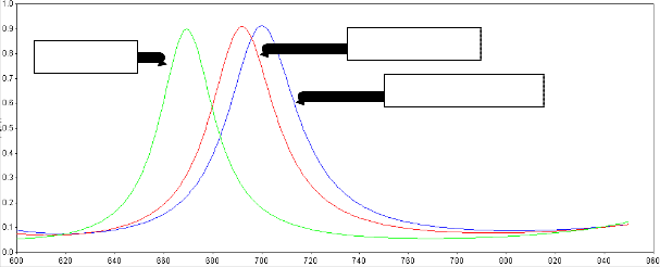
Wavelengths (nm)
Fig. (2) Transmission vs. wavelength for design band pass filter.
The other design consists of 13 layers, below the table (2) of constructions parameters and the characteristic of the transmission curve for this design.
Table (2) layer structure of narrow band pass filter
No | Materials | Thicknesses (nm) |
1 | TiO2 | 76.987 |
2 | SiO2 | 118.632 |
3 | TiO2 | 76.987 |
4 | SiO2 | 118.632 |
5 | TiO2 | 76.987 |
6 | SiO2 | 237.263 |
7 | TiO2 | 76.987 |
8 | SiO2 | 237.263 |
9 | TiO2 | 76.987 |
10 | SiO2 | 118.632 |
11 | TiO2 | 76.987 |
12 | SiO2 | 118.632 |
13 | TiO2 | 76.987 |
IJSER © 2013 http://www.ijser.org
International Journal of Scientific & Engineering Research, Volume 4, Issue 8, August-2013 1860
IS 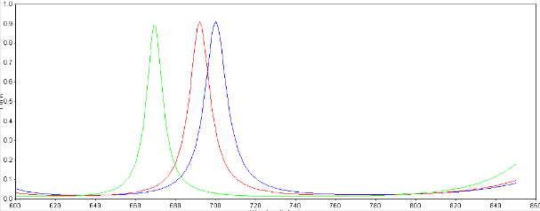
Wavelengths (nm)
Another design consist of (23) layers the constraction parameters and characteristics of the transmission design shows in table (3) below. From this design we see the bandwidth is very narrow compared with the tow design above. All the design tested at normal and oblique angle of incidence, therefore the bandwidth shifted to the short wavelengths at oblique angle of incidence.
Table (3) layer structure of narrow band pass filter
No | Materials | Thicknesses (nm) |
1 | TiO2 | 76.987 |
2 | SiO2 | 118.632 |
3 | TiO2 | 76.987 |
4 | SiO2 | 118.632 |
5 | TiO2 | 76.987 |
6 | SiO2 | 237.263 |
7 | TiO2 | 76.987 |
8 | SiO2 | 118.632 |
9 | TiO2 | 76.987 |
10 | SiO2 | 118,987 |
11 | TiO2 | 76.987 |
12 | SiO2 | 237.263 |
13 | TiO2 | 76.987 |
15 | SiO2 | 118.632 |
16 | TiO2 | 76.987 |
17 | SiO2 | 118,987 |
18 | TiO2 | 76.987 |
19 | SiO2 | 118.632 |
20 | TiO2 | 76.987 |
IJSER © 2013 http://www.ijser.org
International Journal of Scientific & Engineering Research, Volume 4, Issue 8, August-2013 1861
ISSN 2229-5518
21 | SiO2 | 118,987 |
22 | TiO2 | 76.987 |
23 | SiO2 | 118.632 |
3. Conclusion:
Wavelengths (nm)
The basic design of narrow bandpass filter is constructed on the Fabry-Perot interferometer. The bandwidth of the multi-cavity (MC) filter depends on the ratio of the refractive indices of the materials chosen, the material chosen for the cavity layer and the number of periods in the mirror structures. It also depends on the number of half-wave optical thick layers in the spacers.
1- H. A. Macleod, "Thin-Film Optical Filters", 3rd Ed. Chap.7, Institute of Physics Publishing, Bristol and Philadelphia (2001).
2- A. Thelen, "design of optical interference coatings" McGRAW-HILL Book Company (1989).
3- J. S. Seeley,"Resolving power of multi-layer filter", J. Opt. Soc. Am., 54, 342-346, (1964).
4- P. H. Berning, “Use of equivalent films in the design of infrared multilayer Antireflection coatings”, J. Opt. Soc. Am., 52, 431-436, (1962).
5- D. Morton, "Design of Multi-Band Square Band Pass Filters, " Society of Vacuum Coaters ,
505/856-7188 , moorestown , NJ (2003) .
6- Moreno, J. Araiza and M. Avendano, "Thin-Film Spatial Filters," Optics Letters, 30, 8, 914-
916 (2005).
IJSER © 2013 http://www.ijser.org
Internatio nal Journal of Scientific & Engineering Research, Volume 4, Issue 8, August-2013
ISSN 2229-5518
1862
7- S. Lauouche, L. Martinu,"Open-Filters: open-source software for the design, optimization, and synthesis of optical filters" Appl. Opt., 47, C219-C230 (2008).