International Journal of Scientific & Engineering Research, Volume 3, Issue 11, November-2012 1
ISSN 2229-5518
Design and Performance Analysis of Dual band
Circularly Polarized C-Slot Patch Antenna
Manoj Kumar Dubey, Rahul Vivek Purohit
Abstract—In this paper dual band aperture coupled Circularly Polarized (CP) C-Slotted antenna with a small frequency ratio exited through a single feed is proposed for GPS application. The optimized design of C- Slot antenna has been validated using IE3D Electro- magnetic wave simulator. The C-slot is asymmetrical about the centre of the antenna. The antenna parameters can be optimized by changing the physical parameters like as length of the slot , permittivity of the dielectric etc.The measured 10-dB return loss bandwidth of the optimized slot are 44.91% & 6.8%for the lower and upper band respectively. The measured Axial Ratio is 0.14 at 1.29 GHz. The overall antenna gain is more than 5.5 dBic and efficiency is 80%.A dual frequency aperture coupled patch antenna may provide a sub-
stitute to large bandwidth planner antenna.
.
Index Terms— Microstrip antenna, dual band antenna, patch antenna, Circular polarization, circularly polarized antenna, GPS an- tenna
1 INTRODUCTION
—————————— ——————————
M icrostrip antennas are very popular due to their compact size, low cost, simple in manufacturing and conformability. Most interesting feature of the aperture coupled microstrip antenna is that these are reconfigurable. Depend upon the
type of feeding, shape and size of the slot, patch antenna has a lot of application in Radar, Mobile and Satellite Communica- tion.
A variation of the aperture coupled patch antenna en- hances the various parameters. By changing the physical pa- rameters of the antenna are investigated, wideband operation can be achieved [1]. In [2], Kai-Ping Yang et al had proposed a design for dual band circularly polarized (CP) square patch antenna.Thedesigned is achieved by four T slits at patch edg- es. They reduced 36 % size of the slot in their design. Circular- ly Polarized rectangular bent slot antenna baked by rectangu- lar cavity to achieve input impedance, axial ratio and radiation pattern [3]. Rashid A Sayeed et al had designed aperture cou- pled feed microstrip antenna for WLAN.Circular Polarization is the resultant of two signals having same amplitude and 90 degree out of phase. Circular polarization can be achieved if two orthogonal modes are excited with a 90o time phase dif- ference between them. Regardless of the receiver orientation CP will able receiving a component of the transmitted signal. It is only possible due to the wave having the angular varia- tion.
————————————————
Manoj Kumar Dubey is currently persuing masters degree program in Electronics & Communication engineering in Mahamaya Technical Uni- versity Noida, India, PH-+919899667618. E-mail: erec.manoj@gmail.com
Rahul Vivek Purohit is currently PhD scholar in the field of pattern recog- nitiontechniques used in sensors in Jamia Milia Islamia University , New Delhi , India. E-mail: rahul_yagya@yahoo.com
This can be accomplished by adjusting the physical dimensions of the patch and using either single, two or more feeds [4].The microstrip antenna with an annular - ring patch excited by L-Slot is proposed by Cai et al. Dual band CP is occur to magnetic circulating currents flowing in the opposite direction along the ring with two different specified frequen- cies [5].In [6], Bao et al optimized circularly polarized patch antenna with small frequency ratio and compact in size. The size of the slot is reduced up to 53 % and angular frequency ratio of resonant modes is tunable and suitable for wireless communication. Using E-Shaped structure the antenna is de- signed for Wide band operation about 31.6- 40 GHz. It is suit- able for millimeter wave application [7].Gh. Z. Rafi et al sug- gested a low profile integrated patch antenna for GPS-DSRC application. Antenna operates at L1 GPS frequency of 1.575
GHz with circularly Polarized and 5.88 GHz with vertical line- ar polarization [8]. Nasimuddin , Zhi Ning et al proposed s- Shaped Circularly Polarized patch antenna with small fre- quency ratio for GPs application.Asymmetrical S-shaped slot cut at center which provides 16% upper band and 12.5 % low- er band 10-dB return loss Bandwidth respectively and the Axi- al ratio 6.9% for lower band and 0.6% for upper band [9].
Three Wilkinson power combiners have been used to
combine the signals from the four feed-lines at the slots with
same amplitudes and 90o phase difference.
2 DESIGN OF DUAL-FREQUENCY CP- SLOTTED PATCH ANTENNA
The antenna structure comprising two substrates, the lower substrate material is FR4, relative permittivity 4.4 (Loss tangent 0.02) – and the upper substrate is foam which has a relative permittivity of 1.06 (Loss tangent 0.0). A 50 Ohm coax-
IJSER © 2012
http://www.ijser.org
International Journal of Scientific & Engineering Research, Volume 3, Issue 11, November-2012 2
ISSN 2229-5518
ial probe feeds the top radiating patch through a via hole in the bottom layer; the ground plane size is 90 mmX90 mm.
The designed shape of the antenna is shown in figure
2.The radiating patch is feed through an aperture coupled 50
ohm single feed microstip line under the ground plane.The

fined Bandwidth , in other way frequency range for which antenna performed and give satisfied results. In aperture cou- pled feed, RF energy coupled from single feed line to the radi- ating patch [4].Following steps are sequentially used to design the antenna [1]-[9].
1. First we have to determine initial dimensions of the radiating C- slot for the lower band and the constraint is size of antenna.

2. Optimization of aperture coupled feeding to achieve
3 h
4 y a
resu -
stan
Para N meter o
mm N
o
Pareme mm ter
Fig.2: Designed C-Slot Antenna
3 SIMULATION RESULTS
After the simulation of above design on Zeland_IE3D_v14.10 we get the following results. These all results are plotted against frequency.
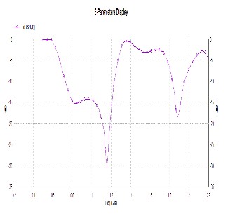
A. Return Loss
Fig.1: Cross sectional view of antenna [9]
Table-Dimensions of the patch
The input reflection coefficient obtained from IE3D ver.
14.0[10] for the dual band Circularly Polarized high gain mi-
crostrip antenna is shown in Fig.3.For the proposed structure
shown in Fig.3, the measured 10 dB return loss is -30.2 at 1.15
GHz and -17.8 at 1.89 GHz.
IJSER © 2012
http://www.ijser.org
International Journal of Scientific & Engineering Research, Volume 3, Issue 11, November-2012 3
ISSN 2229-5518 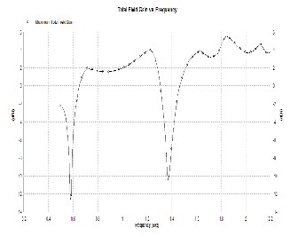
Fig.5: Total Field Gain Vs Frequency
Fig.3: Return loss Vs Frequency
B. Axial Ratio
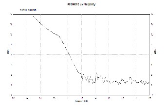
The value of axial ratio for Circularly Polarized antenna should be low. Simulation result for the Axial Ratio is shown in Fig.4.In the designed structure the axial ratio is 0.14 at 1.29
GHz.
Fig.4: Axial Ratio Vs Frequency
C. Total Field Gain
Simulated result obtained for the above proposed de- sign is shown in Fig.5. At the lower resonant frequency gain is 3.34 .On comparing the gain of C- slot antenna with the conventional antenna [9], it is improved. The maximum achievable gain is 5.5 dBi
D. Total Directivity
The directivity for the propose design is 4.01at
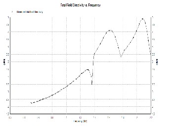
1.15GHz.The simulated result is shown in Fig.6. The range of
Directivity is 4-8 dBi in between 1.45 - 2.2 GHz.
Fig.6: Total directivity Vs Frequency
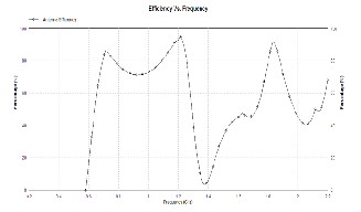
E. Antenna Efficiency
The simulated result of the C-Patch antenna efficiency is shown in Fig.7 .The measured Antenna Efficiency is 81% at 1.15 GHz.
IJSER © 2012
http://www.ijser.org
International Journal of Scientific & Engineering Research, Volume 3, Issue 11, November-2012 4
ISSN 2229-5518
H. Radiation Pattern
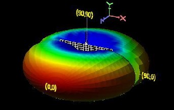
Radiation pattern describes the efficiency of antenna.. For proposed structure the radiation pattern shown in Fig.10 .
Fig.7: Antenna Efficiency Vs Frequency
F. Radiation Efficiency
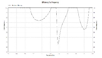
It is the very important performance parameter of an- tenna specification. Radiation Efficiency result is shown in Fig.8. Radiation Efficiency is 83% at 1.15 GHz.
Fig.10: Radiation Pattern
4. CONCLUSION
Fig.8: RadiationEfficiency Vs Frequency
In This paper we proposed a single feed circularly po- larized dual band antenna with a small frequency ratio .In C- slot patch design the lower band width is 44.91 % and also a suitable small axial ratio is 0.14.The main interesting point in this simulated design is Return Loss which is -30.2dB.Total field directivity is 4-8 dBi.from the simulated result this C-Slot Shape is very much appropriate for designing the antenna array to achieve high performance for the GPS applications.
G. Current Distribution
The current distribution for the designed slot is shown in Fig.9.
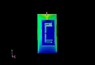
Fig.9: Current Distribution
IJSER © 2012
5. REFERENCES
[1] S. D. Targonski, R. B. Waterhouse and D. M. Pozar, “Design of Wide-Band Aperture-Stacked Patch Microstrip Antennas,” IEEE Trans. Antennas Propag., vol. 46, no. 9, pp.
1245–1251, 1998.
[2] Yang Kai-Ping and Wong Kin-Lu 2001. Dual-Band Cir-
cularly-Polarized Square Microstrip Antenna. IEEE Trans-
actions on Antenna and Propagation, Vol.49, No.3.
[3] Shi Song, Hirasawa Kazuhiro and Chen Zhi Ning 2001.
Circularly Polarized Rectangular Bent Slot Antennas
Backed by a Rectangular Cavity. IEEE Transactions on An-
tenna and Propagation, Vol.49, No.11.
[4] Sayeed Rashid A. and Alshamary Mahmoud 2005. De-
sign of Single Fed Aperture Coupled Microstrip Antennas
for WLAN. IEEE 1-4244-0000-7/05.
[5] Cai C.-H., Row J.-S. and Wong K.-L. 2006. Dual-
frequency microstrip antenna with dual circular polariza-
tion. ELECTRONICS LETTERS Vol. 42 No. 22.
[6] X. L. Bao and M. J. Ammann, “Dual-frequency circular-
ly-polarized patch antenna with compact size and small
frequency ratio,” IEEE Trans. Antennas Propag., vol. 55, no.
http://www.ijser.org
International Journal of Scientific & Engineering Research, Volume 3, Issue 11, November-2012 5
ISSN 2229-5518
7, pp. 2104–2107, 2007.
[7] He Wei, Jin Ronghong, and GenJunping g 2008. E-Shape
Patch with Wideband and Circular Polarization for Milli-
meter-Wave Communication .IEEE Transactions on Anten-
na and Propagation, Vol.56 , No.3.
[8] Rafi Gh. Z., Mohajer Mehrbod, Malarky Alastair,
Mousavi Pedram, and Safavi-Naeini Safieddin 2009. Low-
Profile Integrated Microstrip Antenna for GPS-DSRC Ap-
plication. IEEE Transactions on Antenna and Propagation,
Vol.8.
[9] Nasimuddin, Chen Zhi Ning, and Qing Xianming 2010.
Dual-Band Circularly Polarized -Shaped Slotted Patch An-
tenna With a Small Frequency-Ratio. IEEE Transactions on
Antenna and Propagation, Vol.58, No.6.
[10] IE3D Version 14.0, Zeland Software Inc... Fremont,
CA, Oct. 2007.
[11] Balanis Constantine A. 2007. Antenna Theory Analysis
& Design. John Wiley & Sons, 2nd Ed.
IJSER © 2012
http://www.ijser.org