
International Journal of Scientific & Engineering Research, Volume 5, Issue 7, July-2014 1254
ISSN 2229-5518
Design and Optimization of Roller Conveyor
System
D.K. Nannaware [1], R.R. Kharde [2]
PG student, Pravara Rural Engineering College,Loni, India. [1] Professor, Pravara Rural Engineering College,Loni, India. [2]
Paper contains geometrical modeling and finite element modeling of existing design and optimized design. Geometrical modeling is done using Catia V5R19 and finite modeling was done with the help of Ansys .Results shows safe design of optimized design. Optimization gives optimum design for same loading condition with huge amount of weight reduction. Using optimized procedure and using practical available structure 39.26% weight reduction is achieved
A conveyor system is a common piece of mechanical handling equipment that moves materials from one location to another. Conveyors are especially useful in applications involving the transportation of heavy or bulky materials. Conveyor systems allow quick and efficient transportation for a wide variety of materials, which make them very popular in the material handling and packaging industries. Many kinds of conveying systems are available, and are used according to the various needs of different industries. There are chain conveyors (floor and overhead) as well. Chain conveyors consist of enclosed tracks, I- Beam, towline, power & free, and hand pushed trolleys. Conveyor systems are used widespread across a range of industries due to the numerous benefits they provide. Conveyors are able to safely transport materials from one level to another, which when done by human labor would be strenuous and expensive.
• Conveyors can be installed almost anywhere, and are much safer than using a forklift or other machine to move materials.
• Also can move loads of all shapes, sizes and weights. Also, many have advanced safety features that help in preventing accidents.
There are a variety of options available for running conveying systems, including the hydraulic, mechanical and fully automated systems, which are equipped to fit individual needs.
Conveyor systems are commonly used in many industries, including the automotive, agricultural, computer, electronic, food processing, aerospace, pharmaceutical, chemical, bottling and canning, print finishing and packaging. Although a wide variety of materials can be conveyed, some of the most common include food items such as beans and nuts, bottles and cans, automotive components, scrap metal, pills and powders, wood and furniture and grain and animal feed. Many factors are important in the accurate selection of a conveyor system. It is important to know how the conveyor system will be used beforehand. Some individual areas that are helpful to consider are the required conveyor operations, such as transportation, accumulation and sorting, the material sizes, weights and shapes and where the loading and pickup points need to be.
In this paper the latest development of belt conveyor is done. It concentrates on energy efficiency, route optimization, distributed power, analysis and simulation (1). It is observed that the weight of the conveyor part increased due to the critical part of the system (2).The amount of processing that the device increase as the circuit design becomes more complex (3). ADAMS CAD system is used as simulation technique (4). Determination of the number of conveyors into the objective. To develops two staged method to optimized and maximum profit (5). Various types of cost estimation techniques are given for optimization of steel frames (6). The standard design where each roller is connected to line shaft, where the first roller in conveyor connected to line shaft and subsequent rollers are connected by sequential belts are studied(7).to identify the conveyor dynamic relationship, based on this formulate dynamic network model for the performance evaluation (8). In this paper deal with special kind of flow shop processing which quit different from the usual flow shop (9).
IJSER © 2014 http://www.ijser.org
International Journal of Scientific & Engineering Research, Volume 5, Issue 7, July-2014 1255
ISSN 2229-5518
1. Gravity Conveyor systems
2. Powered Belt Conveyor systems
3. Pneumatic conveyor systems
4. Vibrating conveyor systems
5. Flexible conveyor systems
6. -Vertical conveyor systems and spiral conveyors
7. Live Roller Conveyor systems
1. Check design of existing conveyor system.
2. ANSYS APDL codes or Catia V5R19 for drawing of existing system.
3. ANSYS is used for linear static, modal, transient and optimization analysis.
4. Optimization of conveyor assembly for weight
reduction.
5. Comparison between existing and optimized design.
6. By using the “STEEL TABLE” and “UNIVERSAL TESTING MACHINE” find out the maximum loading and maximum
bending stress of the channel.
The aim of this project is to redesign existing gravity roller conveyor system by designing the critical parts (Roller, Shaft, Bearing & Frame), to minimize the overall weight of the assembly and to save considerable amount of material.
Gravity roller Conveyor has to convey 3500 N
load, 30 inch above ground and inclined at 4 degree. Fig.
2.1 shows roller conveyor assembly. Components of conveyor are as follows,
sr. No. | Name of Component | Weight (Kg) | |
1 | C- Channel for Chassis | 39.066 | |
2 | Rollers | 111.1181 | |
3 | Shafts | 20.7421 | |
4 | Bearing | 2.994 | |
5 | C- Channel for Supports | 19.70 | |
Total Weight of assembly | 193.6121 |
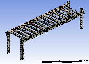
Geometrical modeling done with the help of
CATIA V5R17.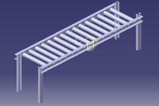
A static analysis calculates the effect of steady loading condition on a structure, while ignoring inertia and damping effects, such as those caused by time varying loads.
A static analysis can, however, include steady inertia load (such as gravity and rotational).
Design and analysis of roller conveyor for weight optimization & material saving and time varying load that can be approximated as static equivalent loads (such as
static equivalent wind and seismic loads commonly defined in many building codes). Required properties of
IJSER © 2014 http://www.ijser.org
International Journal of Scientific & Engineering Research, Volume 5, Issue 7, July-2014 1256
ISSN 2229-5518
material are selected. Static analysis determines the
displacements, stresses, strains, and forces in structures or components caused by lodes that do not induce significant inertia and damping effects. Steady loading and response conditions are like that is, the loads and the structure’s response are assumed to vary slowly with respect to time.
Critical load condition-
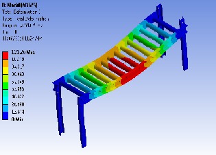
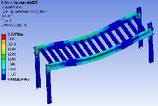
Load is acting on any four rollers hence by considering 3500 N load acting on four rollers maximum deflection, maximum stress values are checked for existing design.
-Weight of the model is 193 kg
- Maximum deflection plot shown in fig. 5.1
- Maximum stress plot shown in fig. 5.2
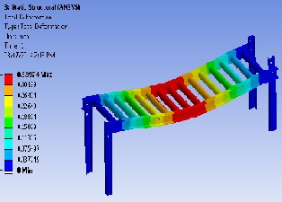
Load of 3500 N is applied on 4 rollers which located at the centre of the conveyor system. We get the maximum deflection and maximum stress.
• Modal analysis is carried out to find natural frequency and mode shapes.
• As the loading will be in vertical direction (gravity) the mode shape which will show movement in vertical direction is important.
There are different types of critical mode shapes occur in the conveyor system. We selected the transverse mode shape which require for the analysis purpose.
Result from Modal analysis-
• From the results it is clear that mode shape in fig will have maximum motion in vertical direction. So natural frequency should be greater than the excitation frequency.
• Natural frequency is 59.679 Hz.
As factor of safety of C-Channels and Rollers is very high there is scope of weight reduction in this component.
Optimized design on the basis of following criteria.
• Flange Width
• Flange thickness
• Web height
• Web thickness
• Roller Outer diameter
• Roller thickness
• Selecting available components which are similar to optimized design.
• Select ISJC 100 and ISJC 75 C-channels for
chassis and supports respectively
• Roller Outer diameter is 60 mm and roller thickness 5 mm
Static structural analysis is done with the help of
ANSYS workbench.
IJSER © 2014 http://www.ijser.org
International Journal of Scientific & Engineering Research, Volume 5, Issue 7, July-2014 1257
ISSN 2229-5518
Static structural analysis is done with the help of
ANSYS workbench.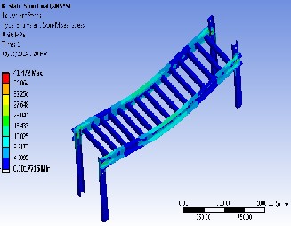
Model analysis is done with the help of ANSYS
workbench.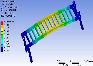
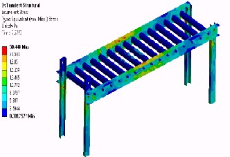
Transient structural analysis is done with the help of
ANSYS workbench.
Sr. No | Name of Component | Weight (Kg) Optimized Design | Weight (Kg) Existing Design |
1 | C-Channels for Chassis | 25.62 | 36.066 |
2 | Rollers | 50.92 | 111.1181 |
3 | Shafts | 20.7421 | 20.7421 |
4 | Bearings | 2.994 | 2.994 |
5 | C-channels for Supports | 17.32 | 19.70 |
Total Weight of Conveyor | 117.5961 | 193.6121 |
1) From above chart we can find the great change in weight of optimized design and existing design. (60 Kg. weight reduction)
2) Here we can observe changes in 3 main components, i.e. C-channels for Chassis, C- Channels for Supports and Rollers due to optimization.
Design | Max. Def (mm) | Natural Freq. (Hz) | Max. Stress (N/mm2) |
Existing | 0.3397 | 59.67 | 28.047 |
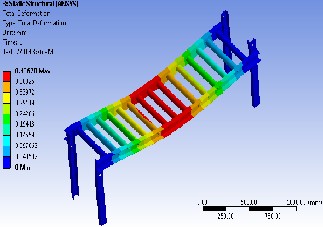
Optimized | 0.4367 | 65.87 | 41.47 |
IJSER © 2014 http://www.ijser.org
International Journal of Scientific & Engineering Research, Volume 5, Issue 7, July-2014 1258
ISSN 2229-5518
• Existing design calculation shows the factor of safety is very greater than requirement and there is a scope for weight reduction.
• Critical parameter which reduces the weight of C- channels, roller outer diameter and roller thickness.
• Though value of deflection, stress is more in case
of Optimized design, but it is allowable.
• Transient analysis also gives the permissible stress limit i.e. 50.40 Mpa.
• 39.26% of weight reduction is achieved due to
Optimized design.
• 60.73 Kg. weight reduction achieved by optimized design than existing design.
1) Fatigue analysis for life calculation.
Fatigue analysis can be done by obtaining the SN curve. ANSYS predicts the number of cycles of different regions.
2) Buckling analysis.
Buckling analysis of support channels can be done to find maximum load.
3) Non-linear analysis.
Material non-linearity can be considered to find more accurate results.
4) Selection of appropriate material.
By selecting inferior quality of material further weight reduction of conveyor is possible.
5) Thermal Analysis can be considered for further study.
[1]. M. A. Alspaugh, “Latest Developments in Belt Conveyor Technology” MINExpo 2004, Las Vegas, NV, USA. September 27, 2004
[2]. S.H. Masood · B. Abbas · E. Shayan · A. Kara “An investigation into design and manufacturing of mechanical conveyors Systems for food processing”, Springer-Verlag London Limited 2004
[3]. Dima Nazzal , Ahmed El-Nashar “Survey Of Research
In Modeling Conveyor-Based Automated Material
Handling Systems In wafer fabs” Proceedings of the
2007 Winter Simulation Conference.
[4]. Chun-Hsiung Lan, “The design of a multi-conveyor
system for profit maximization” International Journal
Adv Manuf Technol (2003) 22: 510–521.
[5]. John Usher, John R, G. Don Taylor “Availability
modeling of powered roller conveyors”.
[6]. Espelage W, Wanke E.“Movement minimization for unit distances in conveyor flow shop processing”,
[7]. C.Sekimoto “Development of Concept Design CAD
System”, Energy and Mechanical Research Laboratories, Research and Development Center, Toshiba Corporation.
[8]. Ying WANG, Chen ZHOU “A Model and an analytical method for conveyor system in distribution centers”, J Syst Sci Syst Eng (Dec 2010) 19(4): 408-
429.
[9]. R. Long, T. Rom, W. H¨ansel, T.W. H¨ansch, J.
Reichel “Long distance magnetic conveyor for
precise positioning of ultra cold atoms” Eur. Phys. J.
D 35, 125–133 (2005).
IJSER © 2014 http://www.ijser.org