International Journal of Scientific & Engineering Research, Volume 3, Issue 11, November-2012 1
ISSN 2229-5518
Design and Implementation of VLSI Architecture for
Mixed Radix FFT
Dr.Y.Padma Sai*, Y.Swetha Sree*
*(Department of ECE, VNR VJIET, Hyderabad, AP, INDIA Email: ypadmasai@gmail.com)
*(Department of ECE, VNR VJIET, Hyderabad, AP, INDIA
Email: swethasree.ece@gmail.com)
ABSTRACT
The main objective of this paper is to design and implement the VLSI architecture for Mixed Radix FFT. This architecture is proposed for memory based Fast Fourier transform (FFT) to support less memory size and area reduction .The pipelined architecture would cost more area and power than memory based architecture.
Index terms: Continuous data flow, Radix-2 Fast Fourier transform, Radix-4 Fast Fourier transform, mixed radix FFT.
1. INTRODUCTION
Digital signal processing is one of the core technologies, in rapidly growing application areas, such as wireless communications, audio and video processing and industrial control.. DSP has become a key component, in many of the consumer, communications, medical and industrial products which implement the signal processing using microprocessors, Field Programmable Gate Arrays (FPGAs), Custom ICs etc.
DSP techniques have been very successful because of the development of low-cost software and hardware support. For example, modems and speech recognition can be less expensive using DSP techniques. DSP processors are concerned primarily with real-time signal processing.
Fast Fourier transform (FFT) has an important role in many digital signal processing (DSP) systems. E.g., in orthogonal frequency division multiplexing (OFMD) communication systems, FFT and inverse FFT are needed. The OFMD technique has become a widely adopted in several wireless communication standards.
Today, various FFT processors, such as pipelined or memory-based architectures, have been proposed for different applications. However, for long-size FFT processors, such as the 2048-point FFT, the pipelined architecture would cost more area and power than the memory-based design. Hence, memory based approach has
gained more and more attention recently in FFT processor designs for long-size DFT applications.
For the memory-based processor design, minimizing
the necessary memory size is effective for area reduction since the memory costs a significant part of the processor. On the other hand, the FFT processor usually adopts on-chip static random access memory (SRAM) instead of external memory. The reason is the high-voltage I/O and the large capacitance in the printer-circuit-board (PCB) trace would increase power consumption for external memory.
To minimize the necessary memory size, an in- place approach is taken for both butterflies output and I/O data. That is, the output data of butterflies are written back to their original location during the computation time. Moreover, for the I/O data, the new input data x[n] would be put in the location of the output data X[n] of the previous FFT symbol. On the other hand, for the memory-based processor, the high-radix structure would be taken to increase the throughput to meet real-time requirements.
In this brief, mixed-radix FFT is proposed to optimize the memory-based FFT processor design. It supports not only in-place policy to minimize the necessary memory size for both butterflies output and I/O data but also multibank memory structure to increase its maximum throughput to satisfy more system applications without memory conflict. After the algorithm is introduced, we take the 16 -point FFT as an illustrative example. Finally, a low- complexity hardware implementation of an index vector generator is also proposed for our algorithm.
2. DESCRIPTION OF FAST FOURIER TRANSFORM
A fast Fourier transform (FFT) is an
efficient algorithm to compute the discrete Fourier transform
(DFT) and its inverse. There are many distinct FFT
algorithms involving a wide range of mathematics, from
IJSER © 2012 http://www.ijser.org
International Journal of Scientific & Engineering Research, Volume 3, Issue 11, November-2012 2
ISSN 2229-5518
simple complex-number arithmetic to group theory and number theory; this article gives an overview of the available techniques and some of their general properties of the FFT.
The fast Fourier transform (FFT) is simply a class of special algorithms which implement the discrete Fourier transform with considerable savings in computational time. It must be pointed out that the FFT is not a different transform from the DFT, but rather just a means of computing the DFT with a considerable reduction in the number of calculations required.
Since this tutorial is intended as an introduction to the Fourier transform, a rigourous development of the underlying theory of the FFT will not be attempted here. While it is possible to develop FFT algorithms that work with any number of points, maximum efficiency of computation is obtained by constraining the number of time points to be an integer power of two, e.g. 1024 or 2048.
A DFT decomposes a sequence of values into components of different frequencies. This operation is useful in many fields (see discrete Fourier transform for properties and applications of the transform) but computing it directly from the definition is often too slow to be practical. An FFT is a way to compute the same result more quickly: computing a DFT of N points in the naive way, using the definition, takes O(N2) arithmetical operations, while an FFT can compute the same result in only O(N log N) operations. The difference in speed can be substantial, especially for long data sets where N may be in the thousands or millions—in practice, the computation time can be reduced by several orders of magnitude in such cases, and the improvement is roughly proportional to N / log(N). This huge improvement made many DFT-based algorithms practical; FFTs are of great importance to a wide variety of applications, from digital signal processing and solving partial differential equations to algorithms for quick multiplication of large integers.
The most well known FFT algorithms depend upon the factorization of N, but there are FFTs with O(N log N) complexity for all N, even for prime N. Many FFT algorithms only depend on the fact that  is an Nth primitive root of unity, and thus can be applied to analogous transforms over any finite field, such as number-theoretic transforms. Since the inverse DFT is the same as the DFT, but with the opposite sign in the exponent and a 1/N factor, any FFT algorithm can easily be adapted for it.
2.1 Applications of FFT
An FFT computes the DFT and produces exactly the same result as evaluating the DFT definition directly; the only difference is that an FFT is much faster. (In the presence of round-off error, many FFT algorithms are also much more accurate than evaluating the DFT definition
directly, as discussed below.)
Let x0, ...., xN-1 be complex numbers. The DFT is defined by the formula
Evaluating this definition directly requires O(N2) operations: there are N outputs Xk, and each output requires a sum of N terms. An FFT is any method to compute the same results in O(N log N) operations. More precisely, all known FFT algorithms require Θ(N log N) operations (technically, O only denotes an upper bound), although there is no known proof that better complexity is impossible.
To illustrate the savings of an FFT, consider the count of complex multiplications and additions. Evaluating the DFT's sums directly involves N2 complex multiplications and N(N − 1) complex additions [of which O(N) operations can be saved by eliminating trivial operations such as multiplications by 1]. The well-known radix-2 Cooley– Tukey algorithm, for N a power of 2, can compute the same result with only (N/2) log2 N complex multiplies (again, ignoring simplifications of multiplications by 1 and similar) and N log2N complex additions. In practice, actual performance on modern computers is usually dominated by factors other than arithmetic and is a complicated subject (see, e.g., Frigo & Johnson, 2005), but the overall improvement from O(N2) to O(N log N) remains constant.
2.2 Cooley–Tukey algorithm Cooley–Tukey algorithm:
The most common FFT is the Cooley–Tukey algorithm. This is a divide and conquer algorithm that recursively breaks down a DFT of any composite size N = N1N2 into many smaller DFTs of sizes N1 and N2, along with O(N) multiplications by complex roots of unity traditionally called twiddle factors (after Gentleman and Sande, 1966).
This method (and the general idea of an FFT) was popularized by a publication of J. W. Cooley and J. W. Tukey in 1965, but it was later discovered (Heideman & Burrus, 1984) that those two authors had independently re- invented an algorithm known to Carl Friedrich Gauss around 1805 (and subsequently rediscovered several times in limited forms).
The most well-known use of the Cooley–Tukey algorithm is to divide the transform into two pieces of size N / 2 at each step, and is therefore limited to power-of-two sizes, but any factorization can be used in general (as was known to both Gauss and Cooley/Tukey). These are called the radix-2 and mixed-radix cases, respectively (and other variants such as the split-radix FFT have their own names as well). Although the basic idea is recursive, most traditional implementations rearrange the algorithm to avoid explicit recursion. Also, because the Cooley–Tukey algorithm breaks the DFT into smaller DFTs, it can be combined arbitrarily with any other algorithm for the DFT.
IJSER © 2012 http://www.ijser.org
International Journal of Scientific & Engineering Research, Volume 3, Issue 11, November-2012 3
ISSN 2229-5518
2.3 Another types of FFT algorithms
There are other FFT algorithms distinct from Cooley–Tukey. For N = N1N2 with coprime N1 and N2, one can use the Prime-Factor (Good-Thomas) algorithm (PFA), based on the Chinese Remainder Theorem, to factorize the DFT similarly to Cooley–Tukey but without the twiddle factors. The Rader-Brenner algorithm (1976) is a Cooley– Tukey-like factorization but with purely imaginary twiddle factors, reducing multiplications at the cost of increased additions and reduced numerical stability; it was later superseded by the split-radix variant of Cooley–Tukey (which achieves the same multiplication count but with fewer additions and without sacrificing accuracy). Algorithms that recursively factorize the DFT into smaller operations other than DFTs include the Bruun and QFT algorithms. (The Rader-Brenner and QFT algorithms were proposed for power-of-two sizes, but it is possible that they could be adapted to general composite n. Bruun's algorithm applies to arbitrary even composite sizes.) Bruun's algorithm, in particular, is based on interpreting the FFT as a recursive factorization of the polynomial zN − 1, here into real-coefficient polynomials of the form zM − 1 and z2M + azM + 1.
Another polynomial viewpoint is exploited by the Winograd algorithm, which factorizes zN − 1 into cyclotomic polynomials—these often have coefficients of 1, 0, or −1, and therefore require few (if any) multiplications, so Winograd can be used to obtain minimal-multiplication FFTs and is often used to find efficient algorithms for small factors. Indeed, Winograd showed that the DFT can be computed with only O(N) irrational multiplications, leading to a proven achievable lower bound on the number of multiplications for power-of-two sizes; unfortunately, this
comes at the cost of many more additions, a tradeoff no
It was once believed that real-input DFTs could be more efficiently computed by means of the discrete Hartley transform (DHT), but it was subsequently argued that a specialized real-input DFT algorithm (FFT) can typically be found that requires fewer operations than the corresponding DHT algorithm (FHT) for the same number of inputs. Braun’s algorithm (above) is another method that was initially proposed to take advantage of real inputs, but it has not proved popular.
.
3. PROPOSED MIXED RADIX FFT
3.1 Radix_2 FFT Calculator:
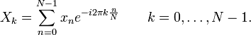
As shown in figure the Clk, Reset, 16-samples and the twiddle factors are the inputs and 16-outputs samples are the outputs . Each and every sample is represented by using the 9-bits of information. The 8-bits are for the information and 1-bit is used for the sign bit representation.
The number of samples is 16, since the four stages of complex butterfly multiplications are required. For the each and every stage requires the different twiddle factors
.The required twiddle factors are delivered by using LUT table. After the fourth stage calculation we can get the 16- samples outputs with real and imaginary parts.
Clk


Reset
RADIX-2
FFT -16
longer favorable on modern processors with hardware multipliers. In particular, Winograd also makes use of the PFA as well as an algorithm by Rader for FFTs of prime sizes.
2.4 FFT algorithms specialized for real and/or symmetric data
In many applications, the input data for the DFT are
purely real, in which case the outputs satisfy the symmetry
16-
samples .
.
Twiddle factors from LUT
calculator
16 output samples

and efficient FFT algorithms have been designed for this situation (see e.g. Sorensen, 1987). One approach consists of taking an ordinary algorithm (e.g. Cooley–Tukey) and removing the redundant parts of the computation, saving roughly a factor of two in time and memory. Alternatively, it is possible to express an even-length real-input DFT as a complex DFT of half the length (whose real and imaginary parts are the even/odd elements of the original real data), followed by O(N) post-processing operations.
Figure 3.1 Block diagram of Radix_2 FFT
3.2 Radix_4 Complex Butterfly:
As shown in the below AR [8:0], AI [8:0], BR
[8:0], BI [8:0], CR [8:0], CI [8:0], DR [8:0], DI [8:0], WAR [8:0], WAI [8:0], WBR [8:0], WBI [8:0], WCR [8:0], WCI [8:0], WDR [8:0], WDI [8:0] are the inputs of 9-bits and A_REAL [8:0], A_IMG [8:0], B_REAL [8:0], B_IMG [8:0], C_REAL [8:0], C_IMG [8:0], D_REAL [8:0], D_IMG [8:0] are the outputs of 9-bits.
IJSER © 2012 http://www.ijser.org
International Journal of Scientific & Engineering Research, Volume 3, Issue 11, November-2012 4
ISSN 2229-5518
The first operation in this module is calculate the complex multiplications of respective twiddle factors like AR [8:0], AI [8:0] with WAR [8:0], WAI [8:0]. In the second operation we can calculate the A_REAL [8:0], A_IMG [8:0], B_REAL [8:0], B_IMG [8:0], C_REAL [8:0], C_IMG [8:0], D_REAL [8:0], D_IMG [8:0] by using the following equations
A_REAL =ar+(crxwr-cixwi)+(brwr-biwi)+drwr-diwi) -- 1. A_IMG=ai+(crwi+ciwr)+(brwi+biwr)+(crwi+ciwr)+(drwi+ diwr) -----2.
B_REAL =ar-(crwr-ciwi)+(brwi+biwr)-(drwi+diwr) -- 3. B_REAL =ai-(crwi+ciwr)-(brwr-biwi)+(drwr-diwi) -- 4. C_REAL =ar+(crwr-ciwi)-(brwr-biwi)-(drwr-diwi) -- 5. C_IMG= ai+(crwr+ciwi)-(brwi+biwr)-(drwi+diwr) -- 6. D_REAL=ar-(crwr-ciwi)-(brwi+biwr)+(drwi+diwr) -- 7.
D_IMG=ai-(crwi+ciwr)+(brwr-biwi)-(drwr-diwi) -- 8
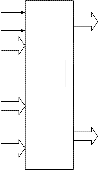
outputs. Every positive Clk edge the Radix_2_ena, Radix_4_ena are enabled or disabled depending the cntrl [1:0] bits. If cntrl value is “00” Radix_2_ena, Radix_4_ena both are disabled, if “01” Radix_2_ena is enable and Radix_4_ena is disable, if “10” Radix_2_ena is disable and Radix_4_ena is enable, if “11” both are activated.
Clk
Radix_2_ena
Controller
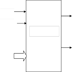
As shown in below figure 3. 2the Clk, Reset, 16- samples and the twiddle factors are the inputs and 16-output samples are outputs. Each and every sample is represented by using the 9-bits of information. The 8-bits are for the information and 1-bit is used for the sign bit representation. The number of samples is 16, since the two stages of complex radix-4 butterfly multiplications are required. For the each and every stage requires the different twiddle
factors .The required twiddle factors are delivered by using
Reset
cntrl
[1:0]
Figure 3. 3 Block diagram of controller
Radix_4_ena
LUT table. After the fourth stage calculation we can get the
16-samples outputs with real and imaginary parts.
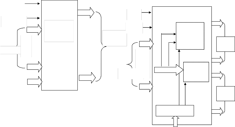
3.4 Top Module:
Clk
Reset
.
16-sample .
Radix-4
16 Point FFT
.
.
16-output samples
Clk
Reset
.
.
Radix_2
FFT_16
CALCULATOR
Radix_4
Radix-
2 FFT
Twiddle factors from LUT
16 samples
FFT_16
CALCULATO
Radix-
4 FFT
Figure 3.2 Block diagram of Radix-4 16 point FFT Calculator
3.3 Controller:
As shown in the below figure 3.3Clk, Reset and cntrl [1:0]
are the inputs and Radix_2_ena , Radix_4_ena are the
CONTROLLER
Cntrl [1:0]
Figure 3.4 Block diagram of Top module
IJSER © 2012 http://www.ijser.org
International Journal of Scientific & Engineering Research, Volume 3, Issue 11, November-2012 5
ISSN 2229-5518
As shown in the figure 3.4, Clk, Reset, cntrl [1:0] and 16_input samples are inputs. Each and every sample is represented as a real part of 9-bits and 9-bits of imaginary bits. This is synchronized design with active low Reset value. Radix-2 of 16-output samples and Radix_4 of 16- outputs samples are the outputs. When ever the Reset is high the both outputs should be in zero value. Depending on the cntrl value we can get either Radix_2 output samples or Radix_4 output samples and both samples are active state when cntrl input value is “11”.
4. RESULTS
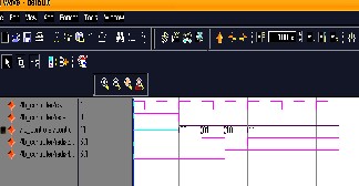
4.1 simulation waveform for controller
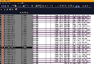
4.2 simulation waveform for top module
5. CONCLUSION
In this brief, a mixed radix FFT has been proposed to optimize the general-size memory-based FFT processor design. It supports the in-place policy for both butterflies output and I/O data to minimize the necessary memory size. Hence, only 2N words memory is required for any size FFT computation for real-time requirements. Furthermore, our proposal also supports the multibank addressing for a high- radix structure without memory conflict by reversing the decomposition order of the previous FFT symbol. Finally, a
low complexity index vector generator has been proposed
for our algorithm. It only costs a few accumulators, making our proposal very suitable for multistandard and multimode OFDMbased applications.
6. FUTURE WORK
This is a novel architecture for any Radix-N of FFT calculation method. It is scalable architecture for any number samples like 32,64,128,256,1024 also. This suitable for different OFDM application with little bit of hardware modification.
7. ACKNOWLEDGEMENT
I am extremely pleased to present myself this dissertation after getting innumerable movements and hard time with a never-ending coordination. I sincerely acknowledge offering my words of thanks to our beloved and respected guide Dr.Y.Padma Sai Professor, Dr.Y.Padma Sai Head of the deportment and Dr.Y.Padma Sai VLSI coordinator who is a constant source of inspiration and encouragement. I sincerely acknowledge offering my words of thanks to my beloved and respected parents for their constant support and encouragement..
8. REFERENCES
[1] L. G. Johnson, “Conflict free memory addressing for dedicated FFT hardware,” IEEE Trans. Circuits Syst. II, Analog Digit. Signal Process. vol. 39, no. 5, pp. 312–316, May 1992.
[2] J. A. Hidalgo, J. Lopez, F. Arguello, and E. L. Zapata, “Area-efficient architecture for fast Fourier transform,” IEEE Trans. Circuits Syst. II, Analog Digit. Signal Process., vol. 46, no. 2, pp. 187–193, Feb. 1999.
[3] B. G. Jo and M. H. Sunwoo, “New continuous-flow mixed-radix (CFMR) FFT processor using novel in-place strategy,” IEEE Trans. Circuits Syst. I, Reg. Papers, vol. 52, no. 5, pp. 911–919, May 2005.
[4] Z.-X. Yang, Y.-P. Hu, C.-Y. Pan, and L. Yang, “Design of a 3780-point IFFT processor for TDS-OFDM,” IEEE Trans. Broadcast., vol. 48, no. 1, pp. 57–61, Mar. 2002.
[5] 3GPP TS 36.201 V8.3.0 LTE Physical Layer—General
Description, E-UTRA, Mar. 2009.
[6] C. Burrus, “Index mappings for multidimensional formulation of the DFT and convolution,” IEEE Trans. Acoust., Speech, Signal Process., vol. ASSP-25, no. 3, pp.
239–242, Jun. 1977.
[7] D. P. Kolba and T. W. Parks, “A prime factor FFT algorithm using high-speed convolution,” IEEE Trans. Acoust., Speech, Signal Process., vol. ASSP-25, no. 4, pp.
281–294, Aug. 1977.
IJSER © 2012 http://www.ijser.org
International Journal of Scientific & Engineering Research, Volume 3, Issue 11, November-2012 6
ISSN 2229-5518
[8] A. M. Despain, “Very fast Fourier transform algorithms hardware for implementation,” IEEE Trans. Comput., vol. C-28, no. 5, pp. 333–341,\ May 1979.
[9] C. L. Wey, S.-Y. Lin, and W. C. Tang, “Efficient memory-based FFT processors for OFDM applications,” in Proc. IEEE Electro/Inf. Technol., May 17–20, 2007, pp.
345–350.
[10] Jaguar II Variable-Point (8-1024) FFT/IFFT, Drey
Enterprise Inc., Crosslake, MN, 1998.
[11] R. Radhouane, P. Liu, and C. Modlin, “Minimizing the memory requirement for continuous flow FFT implementation: Continuous flow mixed mode FFT (CFMM-FFT),” in Proc. IEEE Int. Symp. Circuits Syst., May 2000, vol. 1, pp. 116–119.
[12] Y. Ma, “An effective memory addressing scheme for
FFT processors,” IEEE Trans. Signal Process., vol. 47, no.
3, pp. 907–911, May 1999.
[13] D. Reisis and N. Vlassopoulos, “Address generation techniques for conflict free parallel memory addressing in FFT architectures,” IEEE Trans. Circuits Syst. I, Reg. Papers, vol. 55, no. 11, pp. 3438–3447, Dec. 2008.
 Y. PadmaSai obtained her B.Tech. Degree from Nagarjuna University, Guntur in 1989, and M.E in Systems and Signal Processing from Osmania University, Hyderabad in 1998. Obtained PhD in Electronics
and Communication Engineering, from Osmania University, Hyderabad in 2009. She Started carrier as Quality Control Engineer and served for 5 years in M/S. Suchitra Electronics Pvt. Ltd. Hyderabad, from Feb 1991 to May 1996. Lecturer in the Department of ECE in Deccan College of Engineering and Tech, Hyderabad served for one year, from Jan 1998 to Dec 1998. Lecturer in the Department of ECE VNRVJIET from July 1999 to 10th November 2000. Associate Professor in the department of ECE VNRVJIET from 11th November
2000 to till date. Elevated as professor in the same Department on 21st August 2009. She has taken charge of Head of the Department on 3rd Sep.2012. She is a member of ISTE and Fellow of IETE. She presented 17 research papers in National and International Conferences/Journals. Her areas of research interest are Bio-Medical, Signal and Image Processing.
 . Y.Swetha Sree received her B.Tech. Degree in electronics and communication engineering from MRRIT Institute of Engineering and Technology , affiliated
to JNTU University Hyderabad, ,AP, India, in 2008, is pursuing the M.Tech in VLSI System Design at VNR Vignana Jyothi Institute of Engineering & Technology, Bachupally, Hyderabad, India. Her research interests include VLSI Chip Design (ASIC), Digital Design (FPGA).
IJSER © 2012 http://www.ijser.org