Inte rnatio nal Jo urnal o f Sc ie ntific & Eng inee ring Re se arc h Vo lume 3, Issue 3 , Marc h -2012 1
ISSN 2229-5518
Design and Implementation of Low Cost Home
Security System using GSM Network
Sadeque Reza Khan, Ahmed Al Mansur, Alvir Kabir, Shahid Jaman, Nahian Chowdhury
—————————— ——————————
Security systems are important features of a modern Home [1]. The earliest home security systems date back to the early
1900's. These systems were generally expensive and very hard to monitor. In the past 100 years as technology has changed, home security systems have also changed [2]. Early home s e- curity systems were very expensive and surprisingly ineffec- tive. The requirement for an efficient and cost effective system to cater the disasterous situations and in order to fulfill the security concerns of home owners when the user is away from home, there was a strong need to develop a cost effective and reliable system to satisfy the security related needs of occu- pants [3]. Home security has changed a great deal over the last century and will continue to do so as long as technology con- tinues to progress [4]. This paper mainly focuses on the con- trolling of home appliances remotely and providing security when the user is away from the place. The system is SMS based and uses wireless technology to revolutionize the stan- dards of living. This system provides ideal solution to the problems faced by home owners in daily life [5]. The system is wireless therefore more adaptable and cost-effective. The project is aimed at developing the security of Home against Intruders and Fire. In any of the above cases if any one met while you are out of your home then the device sends SMS to the emergency number provided to it. The device is made up of three components: one or more sensors set up in a remote array depending on the application; a PIC micro-controller; and a GSM module.
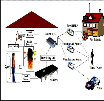
The system contains sensors to detect obstacle, touch, heat, smoke, sound. The whole system is controlled by a PIC micro- controller 16F76. It collects information from the sensors, makes a decision and sends SMS to a corresponding number by using a GSM modem. If it finds any interruption in its sen- sors like if the IR is interrupted then PIC will send a SMS to the home owner and another SMS to the Police Station. In the same way for fire interruption a SMS will be sent to the fire brigade and another to the home owner shown in Fig. 1.
———— ——— ——— ——— ———
Sadeque Reza Kha n is with the dept. of electrical and electronic engineering
(EEE) in Prime University, Ba ngladesh, E-ma il: sa deque_008@yahoo.com
Ahmed Al Ma nsur is currently pursuing PhD degree in EEE in Islamic
University of Technology, Bangladesh, E-ma il: ma nsur.iut@gmail.com
Alvir Ka bir is with the dept of electrical a nd telecommunica tion engineering in
University of Libera l Arts Ba ngladesh, E-mail: alvirka bir@gma il.com
Shahid Jama n is with the dept. of EEE in Ahsa nullah University of Science
a nd Technology (AUST), Ba ngladesh, E-mail: shahid_jaman_aust@yahoo.com
Nahia n Chowdhury is with the dept. of EEE in AUST, Ba ngladesh, E-ma il:
Fig. 1. Proposed System
The design steps and working principles of the system is or-
nahia n.eee@live.com
IJSER © 2012
Inte rnatio nal Jo urnal o f Sc ie ntific & Eng inee ring Re se arc h Vo lume 3, Issue 3 , Marc h -2012 2
ISSN 2229-5518
ganized into different units like controller unit, interfacing unit, GSM module and different sensors. It also requires com- piler to build the assembly program used in PIC microchip.
The control module is built with the microcontroller IC. The central controller is Microchip PIC16F76. It consists of a mi- croprocessor, RAM, EEPROM or EPROM, I/O capacities, ADC, timer, interrupt controller and embedded controller. The microcontroller chip has the versatility to sense inputs and control outputs in the devices. F-family has been selected because it can be burned 1 million times without enabling code protection option. PIC 16F76 is a mid range and 16 series low cost 8 bit microcontroller [6 ]. It consists of 28 I/O (Bi di- rectional lines) with 25mA current in per pin. It also has five channel built-in A/D converter and serial communication.
Modem stands for "modulator / demodulator" and it encodes and decodes signals sent to and from the network servers. A wireless modem shown in Fig. 2 is a network device which connects to a wireless network [7]. Modems are frequently associated with telephone systems, but wireless modems are used with computers and also with communication mediums. Wireless modem interfaces include PCMCIA, Compact Flash, USB and Serial Port. In this project we interface the modem through a Serial Port with a microcontroller IC. AT commands are used to automatically receive the call on system from the preconfigured number and system also sends the voice mes- sage to preconfigured number about the status of appliances and intrusion through AT commands [8].
TABLE 2
THE FOLLOWING SECT ION DESCRIBES T HE AT-COMMAND SET. THE COMMANDS CAN BE T RIED OUT BY CONNECT ING A GSM MODEM TO
ONE OF T HE PC’S COM PORTS.
Command | Description |
ATD<number> | Dial to a number |
ATA | Answer |
AT+CM GF=1 | Set message format to TEXT mode. |
AT+CM GS="number" | Send a message to the telep hone number. |
Table 1, 2 shows the AT-command which can be tried out by connecting a GSM modem to one of the PC‟ s COM ports [9]. The Mobile Station (MS) is the GSM module we use to com- municate. In general however the term Mobile Station refers to a “mobile phone”. The Base Transceiver Station (BTS) is the part of the network that receives and sends data from the Mo- bile Station. The coverage or reception of MS is dependent on proximity and transmission of the BTS it is attached to. The Base Station Controllers (BSC) is a digital switching platform that connects a mobile switching centre MSC and the BTS. The mobile service switching centre (MSC) is the core switching entity in the network [10]. The Gateway Mobile Switching Centre (GMSC) connects a mobile network to a Public Switch- ed Telephone Network (PSTN) which is the backbone of non - cellular telecommunication. The Home Location Register (HLR) acts as a database storing information on all permanent subscribers. Fig. 3 shows the GSM overview.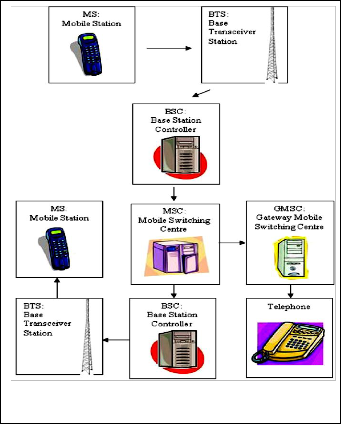
Fig. 2. GSM MODEM
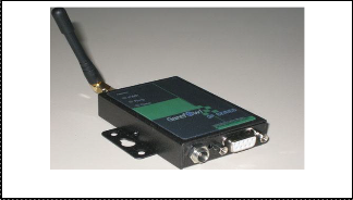
TABLE 1
THE FOLLOWING SECT ION DESCRIBES T HE AT-COMMAND SET.
THE COMMANDS CAN BE T RIED OUT BY CONNECT ING A GSM
MODEM T O ONE OF T HE PC’S COM PORT S.
Fig. 3. GSM Overview
SER © 2012
Inte rnatio nal Jo urnal o f Sc ie ntific & Eng inee ring Re se arc h Vo lume 3, Issue 3 , Marc h -2012 3
ISSN 2229-5518
Interfacing unit includes a MAX232 dual driver/receiver that includes a capacitive voltage generator to supply EIA-232 vol- tage levels from a single 5-V supply and a RS232 which is the most known serial port used in transmitting the data in com- munication and interface [11]. This unit is used to interconnect the PIC with the MODEM.
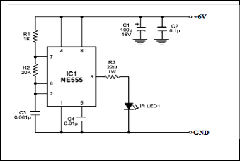
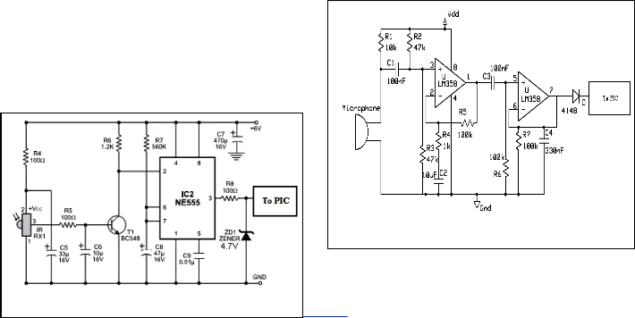
The circuit comprises a transmitter unit and a receiver unit, which are mounted face to face on the opposite pillars of the gate such that the IR beam gets interrupted when someone is standing at the gate or passing through it. The transmitter ci r- cuit (see Fig. 4) is built around timer NE555 (IC1), which is wired as an astable multivibrator producing a frequency of about 38 kHz. The infrared (IR) beam is transmitted through IR LED1. The receiver circuit is shown in Fig. 5 . It comprises IR sensor TSOP1738 (IR RX1), NPN transistor BC548 (T1), ti- mer NE555 and some resistors and capacitors. Timer NE555 is wired as a monostable multivibrator with a time period of around 30 seconds. The transmitter and receiver units are aligned such that the IR beam falls directly on the IR sensor. As long as IR beam falls on the sensor, its output remains low, transistor T1 does not conduct and trigger pin 2 of IC2 remains high. When anyone interrupts the IR beam falling on the sen- sor, its output goes high to drive transistor T1 into conduction and pin 2 of IC2 goes low momentarily. As a result, IC2 gets triggered and its pin 3 goes high to supply 4.2V to PIC 16F76.

It also contains an IR transmitter and Receiver. If the smoke is present IR signal is attenuated due to presence of smoke.IR receiver conductivity is converted into voltage and compared with threshold voltage set by variable resisters. If smoke is present, conductivity of IR receiver is reduced and if it falls bellow threshold then it configures a certain pin of microcon- troller high. Fig. 6 shows a smoke detector circuit.
Fig. 6. Smoke Detector
Sound signal is received from microphone. Amplified by OP AMP LM358 and then compared with fixed DC Voltage. If the amplitude of sound is more than threshold value defined by user is detected and a high signal is transferred to the PIC mi- crocontroller. Here the sensitivity of the circuit can be varied changing R4 value. C4 value can be varied from 220 to 470nF in order to change the circuit speed-response. ICA amplifies about 100 times the audio signal picked-up by the microphone and drives ICB acting as peak-voltage detector. Fig. 7 shows a circuit diagram of the sound detector.
Fig. 4. 38kHz IR Transmitter
Fig. 7. Sound Detector
Fig. 5. Reveiver Unit
The pyro-electric sensing is located in order to detect unauth o-
ER © 2012
Inte rnatio nal Jo urnal o f Sc ie ntific & Eng inee ring Re se arc h Vo lume 3, Issue 3 , Marc h -2012 4
ISSN 2229-5518
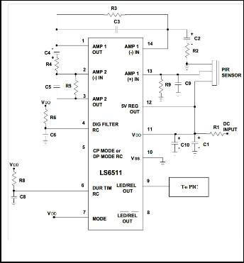
rized intruders. It detects the heat generated from the human body and sends a signal to the PIC notifying a possible intru d- er existence. The electronic circuit uses the CMOS LS6511 i n- tegrated circuit for detecting motion from the PIR sensor and initiating appropriate response. The LS6511 includes two sta g- ing differential amplifier along with a window comp arator. Fig. 8 shows the PIR sensor [12].
Fig. 10 shows the schametic working diagram of the system, where sound detector, smoke detector, PIR sensor, touch sen- sor and obstacle detection are connected with the PIC 16F76.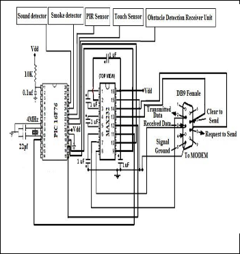
Fig. 8. PIR Sensor Interf ace

The touch sensor is located in the door knob. The touch wire is connected to pin 2 of the 555 timer. This wire uses the body resistance to activate a certain port of PIC. Fig. 9 shows the schematic diagram of the touch sensor circuit.
Fig. 9. Touch Sensor
Fig. 10. Working Diagram
In this system MPLAB v8.40 is used to develop the program for PIC microchip. This compiler consists of Hitech C as well. So this compiler can be used to program in C language. Here the program is divided into six macros. The main macro con- trols the whole program. It calls the three sub macros „Unau- thorized‟, „Fire‟ and „Sound‟ whether there is any fault in the system. Inside these three sub macros two sub macro, „Tx‟ and
„Rx‟ are developed. This two macros help to set communica-
tion with network and send the SMS properly. If there is any
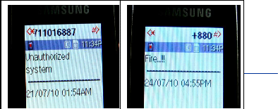
fault in RB0 or RB1 or RB2 pin of microcontroller then the sys- tem will send a preloaded SMS, „Unauthorized System‟ to two certain number of home owner and police station. Again if there is any fault in RB3 the PIC will send a message „Fire!!!‟ to two numbers of home owner and fire brigade. If the condition of RB4 is changed then the system will generate only one SMS
„Unauthorized sound‟ to home owner only.
IJSER © 2012
Inte rnatio nal Jo urnal o f Sc ie ntific & Eng inee ring Re se arc h Vo lume 3, Issue 3 , Marc h -2012 5
ISSN 2229-5518
Fig. 11 shows the flow chart of the total system, which is also clearly showing that if obstacle detector, touch detector, sound detector, heat detector and smoke detector can detect any required signal the system will take necessary action to inform the police, house owner and fire brigade respectively.
This s ecurity home feature is e xpected to draw much attention in the next decades . People are getting more and more concerned about how to protect thems elves and their hous es from e merge n- cies . Thes e emergencies include not only thief intrus ion, but also fire attack. This device provides a means for being able to s ecure- ly monitor a hous e by us e of s ensors integrated with a micro - controller and a GSM unit. SMS provides an economica l and convenient way to alert us ers of a poss ible intrus ion into the property. The us e of mob ile hands ets as a client device to rece ive warning mes s ages on implies that the us er will not have to carry an additional p iece o f equip ment as mos t people a lready have a mobile phone with the m mos t of the time. By us ing this s ys tem the s ecurity s ervices like police and fire brigade of a near by re- gion als o be informed about the intrus ion ins tantly and they can take s teps rapidly. So th is s ystem is s afe and cos t effective as well.
Fig. 11. Flow Chart of the system
1. V ishy Karri, J.S . Danie l Lim, “Me tho d and Dev ice to Co mmuni- c ate v ia SMS Afte r a Sec urity Intrusio n”, 1st Interna tiona l Confe- rence on Sensing Technology November 21-23, 2005 Palme rsto n No rth, Ne w Ze aland.
2. Ibrahi m Ge ha, Kfo ury Elie , and Ashraf Jaafar “S AFE HOME© An Adv ance d Ho me Sec urity Syste m”, De partme nt o f Mec hani- c al Eng inee ring Ame ric an Univ e rsity o f Be irut Be irut, Le bano n, Vo lume 2, 2009 , pp 234-239.
3. Nadia S hahee n, Aihab Khan, Malik Sikande r Hay at Khiy al and Qaise r Jave d “Ho me Auto matio n Disaste r Manage me nt Syste m v ia SMS and GSM” JOURNAL OF COMPUTING, V OLUME 3, ISS UE 7, JULY 2011, ISSN 2151 -9617, pp 132-136.
4. The -Histo ry -o f-Ho me -Sec urity 4th July 2010 [Online ]. Av ailable :
Fig. 12 shows the SMS for unauthorized system, Fig. 13 shows the SMS for the fire attack.
http://e zine artic le s.co m
5. Malik S ikandar H ay at Khiy al, Aihab Khan, and Erum S he hzadi “SMS Base d Wire less Ho me Appliance Co ntro l Syste m (HACS) fo r Auto mating Appliance s and Sec urity ”, Issues in Informing Science a nd Informa tion Technology Vo lume 6, 2009 , pp 887-894.
6. PIC 16F76 Mic roc hip Data shee t [Online]. Av ailable :
http://ww1.mic roc hip.co m/do wnlo ads/e n/dev ice doc/30325b.pdf
ER © 2012
Inte rnatio nal Jo urnal o f Sc ie ntific & Eng inee ring Re se arc h Vo lume 3, Issue 3 , Marc h -2012 6
ISSN 2229-5518
7. Wire le ss Mo de m [Online], accesse d o n 6 th June 2010. Av ailable : We b page . http://e n.wikipe dia.o rg/wiki/Wire less mo de m
8. Marriam Butt, Mamoo na Khanam, Aihab Khan, Malik S ikandar
Hay at Khiy al, “Co ntro lling Ho me Applianc es Re mo te ly
Thro ug h Vo ice Co mmand”, (IJACS A) Interna tiona l Journal of Ad- va nced Computer Science a nd Applica tions, S pec ial Issue o n Wire- le ss & Mo bile Ne two rks, pp 35-39.
9. AT Co mmands, GSM AT Co mmands se t [Online]. Av ailable :
http://www.e ng inee rsg arage .co m/tuto rials/atco mmands?pag e =4
10. Intro duc tio n to GSM Ne two rk [Online ]. Av ailable :
http://me dia.wiley .co m/pro duc t_data/e xce rpt/49/04700169/0470
016949.pdf
11. MAX232, DUAL EIA-232 DRIV ERS/RECEIV ERS Av ailable : http://www.datashe e tc atalog .o rg/datashe e t/te xasinstrume nts/m ax232.pdf
12. PIR SENSOR INTERFACE, 10th June 2010. [Online]. Av ailable :
http://www.lsicsi.co m/pdfs/Data_S hee ts/ LS6511.pdf
IJSER © 2012