International Journal of Scientific & Engineering Research, Volume 3, Issue 6, June-2012 1
ISSN 2229-5518
Design and Analysis of Monolithic Microgripper
R.Bharanidaran, T.Ramesh
Abstract—Precision industries require high precision and controlled motion of microgripper. For this purpose compliant mechanism based monolithic microgrippers are used. In this study, a monolithic microgripper is designed adopting topological optimization met hod. MATLab code has been developed to derive the optimized shape of the monolithic microgripper. Post optimization process was carried o ut to overcome the manufacturing difficulties. Thickness of the microgripper was then designed using finite element method ( FEM) to avoid out of plane sagging caused by the self-weight of the microgripper. The structural analysis using FEM was performed to obtain the Geometrical Advantage (GA) of the design. The proposed design of the microgripper proves that the out of plane motion is completely controlled as the thickness of the gripper is optimized and provides a better GA compared to the earlier designs found in the literature. This kind of design may be helpful to the designers who expect the gripping devices to be used in the situation where a minimum out of plane motion is required.
Index Terms— compliant mechanism, FEM, microgripper, topological optimization.
—————————— ——————————
ANIPULATING the micro sized objects with high pre- cision is the challenging task of the precision industries. Presently, large attention is drawn towards the design
and fabrication of micro manipulating devices. Micro manipu- lating devices are to be designed in such a way that they are monolithic in shape and material compliance should be uti- lized in order to avoid wear and frictional error caused by tra- ditional revolute joint. This will emphasize that the compliant monolithic microgripper can be precisely controlled in its mo- tion. Literatures revels that there are many research works have already been carried out in the field of compliant me- chanism and brought out various approaches and methodolo- gies in designing the microgripper. Topology optimization [1], kinematic linkage model [2], intuitively [3] and pseudo rigid body model (PRBM) [4, 5] are the various techniques utilized by the researchers for developing their own designs of the microgripper. Among the various techniques, topology opti- mization is an efficient way of designing a compliant mechan- ism for multi-objective problems.
In this research work, an attempt has been made to design a monolithic microgripper adopting topology optimization method, and Solid Isotropic Material Penalization (SIMP) based method is used as the solver for the algorithm [6]. A MATLab code has been developed by modifying the 104 line MATLAB code [7] to design the compliant mechanism based microgripper. The topological design generated through the MATLAB program is not suitable for manufacturing. It re- quires post optimization are to be carried out so that the feasi- bility of the design proposed by the MATLab program could be utilized in the device. The concept of Post optimization is discussed in Ref. [8] in a detailed manner.
————————————————
![]() T.Ramesh is currently working as an Assistant Professor in The Depart-
T.Ramesh is currently working as an Assistant Professor in The Depart-
ment of Mechanical Engineering in National Institute of Technology, Tri-
chirappalli-620015, India. E-mail: tramesh@nitt.edu
Out of plane sagging of the design due to its self weight can cause severe problem in the precision motion of the micro- gripper. This effect may cause the gripper to bend and leads an inaccurate motion of the gripper. Hence, this could be re- duced or eliminated to a safer level by optimizing a suitable uniform thickness of the gripper design [13].
The effect of self weight in the structure can also be in- cluded in the topological optimization technique. It generates an equivalent topologically optimized design which can have the capability of resisting the effect of out of plane sagging of the microgripper [14]. Topological optimization technique can also be employed to design a three dimensional geometry [15]. But once again the developed three dimensional topology de- sign leads to manufacturing difficulties. In this study, another trial and error method after post optimization technique has been used to find optimum uniform thickness for the micro- gripper.
Developing the design of highly controlled and precision mi- crogripper must consider various design factors such as accu- racy of motion and resolution of jaw movement, geometrical shape, and weight of the microgripper, grasping force of the jaws on the micro object, and importantly electrostatic force. In micro components, the electrostatic force is larger than the inertial force so it is to be included in the design process [9,
10]. From topology optimization method, two dimensional mechanism designs can be achieved, since thickness also im- portant for high precision motion; appropriate uniform thick- ness can be found through minimizing the deformation due to self weight.
Topology optimization is the effective way of designing the compliant mechanism. SIMP method is used to solve the to- pology optimization problem. Here, limited volume of materi- al is distributed over the design domain subjected to objectives and boundary conditions. The Figure 1 shows the initial struc- tural design domain Ω, for microgripper compliant mechan- ism. Initial configuration of the design is considered as two
IJSER © 2012
International Journal of Scientific & Engineering Research, Volume 3, Issue 6, June-2012 2
ISSN 2229-5518
segments that the left side (the shaded portion) is for having the complete mechanism design and the right side (white area) is having jaws for exhibiting the output motions of the me- chanism. The jaws length, the gap between the jaws is treated as the variables that can be freely modified according to the required size of the object. The objective function of the opti- mization here is to maximize the work performed on the spring that is maximizing the output displacement [8].
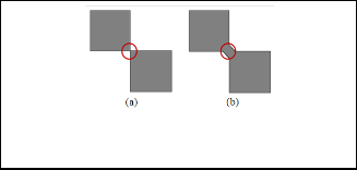
ty are generated in the topological design as shown in Figure
2(b).
F1 F2
F3
Ω
Fig. 1.Domain of compliant mechanism
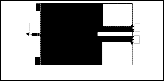
Figure 1 shows the detailed information about the design do- main with the applied forces and the necessary boundary conditions. Unit force F1 is applied at the input spring. The objective function is to obtain a maximum output force F2, and F3 that is maximum output displacement Uout, at the output spring.
Topology optimization problem is written as;
Max (x):
-Uout =F3TU1- F2TU1= ![]() (xe)p u3Tk0u1 - (xe)p u2Tkeu1] (1) Subject to:
(xe)p u3Tk0u1 - (xe)p u2Tkeu1] (1) Subject to:
![]() ≤ f (2) KU =F (3)
≤ f (2) KU =F (3)
Fig. 2. Complex segment for manufacturing (a) Node to node connectivity of between the element, (b) Modified with flexure hinge
To optimize the uniform thickness for the proposed design, the effect of self weight in the structure is performed using ANSYS, a Finite Element Method software package. Solid model of the design is developed in the ANSYS software. Thickness of the microgripper is permitted to vary from 1 mm to 10 mm, to find the optimum uniform thickness of the grip- per. The material considered for this analysis is bio-compatible stainless steel type 304 (Ref: Table 1 for the material proper- ties) and it can also be used in the area of tissue engineering. The solid model of the design is meshed with the 10 node te- trahedron element. The gravitational constant of 9810 mm/s2
is set as input parameter. Analysis is carried out for all thick-
nesses of the microgripper.
TABLE 1
MECHANICAL PROPERTIES STAINLESS STEEL-304
![]()
Symbol Property Magnitude
Where
0≤xmin≤ x ≤1 (4)
υ Poisson's Ratio 0.3
U, F and K are global displacement force and stiffness matrix, respectively
ke,ue, are the elemental stiffness matrix, respectively
K0 is the local stiffness matrix
N number of elements
p is the penalization power
V (x) and V is the material volume and design do-
main volume, respectively
f (volfrac) is the prescribed volume fraction
Initially the design domain is discretized and x is the design variable, xmin vector of minimum element relative density and other material properties are assumed as constant. This me- thod, It distributes the material over the domain as relative density of the material that is, where the material is required to be presence the density is taken as 1 and where it is not, the density is considered as 0.001 [7].
From the manufacturability perspective, the solution obtained through MATLab is required to be processed. For example, the Figure 2(a) shows the node - node connectivity developed in MATLab, which is not a sensible connection in practice. It requires a post design processing hence, modify the design with flexure hinges in the area where node to node connectivi-
E Elastic Modulus 1.93x10⁵ N/mm2
ρ Density(×1000 kg/m3) 8x10⁻⁶ kg/mm3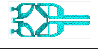
![]()
Fig. 3. Finite Element Model with Boundary Conditions
Structural analysis of microgripper is performed to study the deformation characteristic and to find the geometrical advan- tage of the proposed design. Finite element model of the grip- per and the introduced boundary conditions are shown in Figure 3. The geometrical advantage (GA) of the topological design of the microgripper is measured from the movement of the holding jaws for the applied input displacement of 1 mi- cron in negative x direction (pulling force).
IJSER © 2012
International Journal of Scientific & Engineering Research, Volume 3, Issue 6, June-2012 3
ISSN 2229-5518
The output window of the MATLAB code returns the opti- mized design of microgripper for the given initial design as shown in Figure 4.
From the manufacturing perspective, the MATLab generated design has node to node contact as shown in Figure 5(a), it is impossible to develop using any of the manufacturing processes and it also affects the smooth transfer of load from a member to another. So, the locations where the node to node contact segments generated in the optimized solution are modified as mechanical flexure hinge as illustrated in Figure
5(b). Post optimized model of the gripper is shown in Figure 6.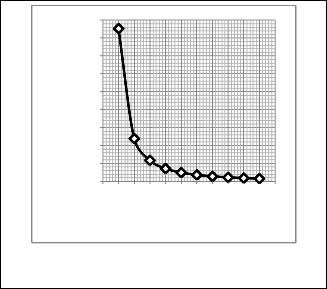
but the percentage deviation is reduced and further it indi- cates that there is no significant effect in the percentage devia- tions in the value of the out-of plane motion. Hence, it is con- cluded that the thickness value falling between 0.5 mm and 0.6 mm will be considered as the optimum thickness of the grip- per.
0.180
0.160
0.140
0.120
0.100
0.080
0.060
0.040
0.020
0.000

0 0.1 0.2 0.3 0.4 0.5 0.6 0.7 0.8 0.9 1 1.1
Thickness of the gripper (mm)
Fig. 4.Topological design of microgripper achieved from MAT- LAB code
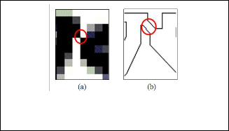
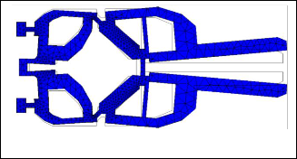
Fig. 7.The effect of thickness of the gripper on Out-of plane mo- tion
Fig. 5.Modified Complex segment for manufacturing (a) Node to node connectivity of between the element, (b) Modified with flexure hinge
Fig.8 Deformed shape of microgripper
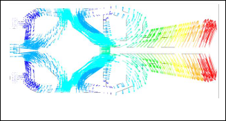
Fig. 6.Post optimized design of microgripper
The effect of self weight is analyzed in the structure and the out-of plane motion characteristic is also observed. The effect of thickness of the gripper against the maximum deformation in out – of plane due its own weight is observed and illu- strated in Figure 7. It is observed from the plot, the percentage of variation of the out – of plane motion of the gripper surface is calculated and it reveals that the thicknesses 0.5mm and 0.6 mm produces a minor deformation out-of the plane. It is found from the graph that during the increases in the thick- ness of the gripper, the out-of plane motion is further reduced,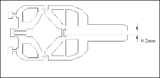
Fig.9 Vector displacement of microgripper
Structural analysis of 0.5 mm thickness microgripper shows that one jaw of the gripper moves to a maximum of 0.0065 mm and the overall opening of the jaws are measured as 0.0130 mm as shown in Figure 8. The Geometrical Advantage of the microgripper is calculated as;![]()
GA = ![]()
IJSER © 2012
International Journal of Scientific & Engineering Research, Volume 3, Issue 6, June-2012 4
ISSN 2229-5518
Fig.10 Stress plot of microgripper
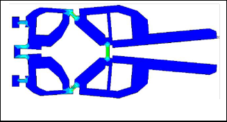
Figure 9 shows the vector plot of the displacement which gives the knowledge on how the rotary motion is developed in the mechanism with respect to flexure hinges. Flexure hinges act as a pin joint in this compliant mechanism. Figure 10 shows von-misses stress developed in the design, maximum stress occurs at the flexure hinge region and the value is lower than the yield stress which shows the conformity of the de- sign.
The proposed optimum design has passed through various steps, which enhances the effectiveness of microgripper design in many aspects. The initial design domain is optimized to achieve the mechanism topology. The optimized result pro- vides the knowledge of the motion of links in the design. The optimized result required to be modified from the manufac- turing aspects, Post optimization was carried out in the design to achieve the manufacturing feasibility. To add thickness for the design, the optimum thickness is found from the deforma- tion results of self-weight analysis for various thicknesses. Microgripper was further analyzed structurally for the input displacement, the output displacement of jaws are measured. Geometric Advantage of the design shows the promising val- ue of the proposed design. Scaling the dimensions to macro level, it can be used where the large displacement is required.
[1] Sigmund, O., ―On the design of compliant mechanisms using topolo-
gy optimization,‖ Mechanics of Structures and Machines, vol. 25, Issue
4, 1997, pp 493-524
[2] Pretty Khare, G. B. Madhab*, C. S. Kumar, and P. K. Mishra, ―Opti- mizing Design of Piezoelectric Actuated Compliant Microgripper Mechanism,‖ 13th National Conference on Mechanisms and Machines (NaCoMM07), IISc, Bangalore, India, Dec. 12-13, 2007
[3] N. Maheshwari, A. Narayana Reddy, Deepak Kumar Sahu and G.K.
Ananthasuresh, ―Miniature Compliant Grippers with Force - Sensing,‖ 14th National Conference on Machines and Mechanisms (Na- CoMM09), NIT, Durgapur, India, Dec. 17-18, 2009.
[4] Mohd Nashrul Mohd Zubir, Bijan Shirinzadeh, Yanling Tian, ―De-
velopment of a novel flexure-based microgripper for high precision micro-object manipulation,‖ Sensors and Actuators, vol. A 150 (2009) pp. 257–266.
[5] Mohd Nashrul Mohd Zubir, Bijan Shirinzadeh, Yanling Tian, ―A new design of piezoelectric driven compliant-based microgripper for mi- cromanipulation,‖ Mechanism and Machine Theory vol. 44 (2009) pp.
2248–2264.
[6] O. Sigmund, ―A 99 line topology optimization code written in Ma t-
lab,‖ Struct Multidisc Optim, vol. 21, pp. 120–127 Springer-Verlag
2001
[7] Martin P. Bendsøe, Ole Sigmund, “Topology optimization: theory, me- thods, and applications,” Springer, 2003.
[8] Chien-Jong Shih, Chih-Feng Lin, Hsin-Yi Chen, ―An integrated de- sign of flexure hinges and topology optimization for monolithic compliant mechanism,‖ Journal of Integrated Design and Process Science, Sep 2006, vol. 10, No. 3, pp. 2.
[9] S.-C. Huang, C.-M. Lee, C.-C. Chiu, W.-L. Chen, ―Topology optimal
compliant microgripper,‖ JSME International Journal, Series A: Solid
Mechanics and Material Engineering vol. 49 (2007), pp. 589–596.
[10] M. Goldfarb, N. Celanovic, ―A flexure-based gripper for small-scale
manipulation,‖ Robotica, vol.17 (1999), pp. 181–187.
[11] G. Alici, B. Shirinzadeh, Enhanced stiffness modeling, ―Identification and Characterization for Robot Manipulators,‖ IEEE Transactions on Robotics vol. 21(2005), pp. 554–564.
[12] A.M. Dollar, R.D. Howe, ―Towards grasping in unstructured envi-
ronments: optimization of grasper compliance and configuration,‖ IEEE/RSJ International Conference on Intelligent Robots and Systems (IROS 2003), Las Vegas, NV, USA, 2003, pp. 3410–3416.
[13] Jingyan Dong, and Placid M. Ferreira, ―Electrostatically Actuated
Cantilever With SOI-MEMS Parallel Kinematic XY Stage,‖ Journal Of
Microelectromechanical Systems, vol. 18, No. 3, Jun 2009.
[14] Bruyneel, M., Duysinx, P., ―Note on topology optimization of conti-
nuum structures including self-weight,‖ Structural and Multidiscipli- nary Optimization, vol.29, pp.245–256 (2005).
[15] Jianhua Rong , Guojing Tang , Qing Quan Liang, Zhenxing Yang, ―A Topology Optimization Method for Three-dimensional Continuum Structures,‖ 6th World Congresses of Structural and Multidisciplinary Optimization Rio de Janeiro, May -Jun 2005, Brazil.
IJSER © 2012